DES-1200M Fast Ethernet Switch System User’s Guide Rev. 03 (MAR.
TABLE OF C ONTENTS TABLE OF CONTENTS ..................................II CHAPTER 1 INTRODUCTION .................. 1 UNPACKING ........................................................... 3 DEVICE DESCRIPTION, FEATURES AND CAPABILITIES ................................................. 4 DES-1200M FRONT AND REAR PANELS ...................... 4 DES-128 8 PORTS 10/100BASE-TX MODULE............... 6 DES-121T GIGABIT 1000BASE-T SWITCH MODULE .....
COLLAPSED BACKBONE LINK .................................. 17 FILESERVER LINK .................................................. 19 MULTI-PORT BRIDGE WITH HIGH-BANDWIDTH BACKBONE .......................................................... 20 CHAPTER 3 INSTALLATION .................. 22 CHOOSING A LOCATION ......................................... 22 SUPPLYING POWER ................................................ 24 CONNECTING THE SWITCH ...................................... 24 CHAPTER 4.
C HAPTER 1 I NTRODUCTION DES-1200M are multi-speed network devices combining Ethernet, Fast Ethernet and Gigabit Ethernet capabilities in a single compact, rack-mountable cabinet. Combining 10Mbps Ethernet, 100Mbps Fast Ethernet and Gigabit Ethernet interfaces in one unit allows these switches to unclog existing LANs and provide a path to efficient, high-speed networking. DES-1200M is a combination of a 4-slot host cabinet which accepts more than 15 different media modules.
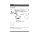
Unpacking Open the shipping cartons of DES-1200M and carefully unpacks its contents. The carton should contain the following items: Figure 1-1. Package Contents DES-1200M 4-Slot Fast Ethernet System AC power cord Rack mounting kit Four Rubber feet This User’s Guide If any item is found missing or damaged, please contact your local reseller for replacement.
D EVICE D ESCRIPTION , F EATURES C APABILITIES AND DES-1200M Front and Rear Panels This section describes the features on the front and rear panels of the DES-1200M unit. Figure 1-2. Front Panel Figure 1-3. Rear Panel All LED status indicators are located on the FRONT panel of the switches. They provide a real-time indication of system and operational status. The ports for connections to other devices and networks are also on the front panels, along with the crossover switches.
LED Indicators Explanation Power The red power indicator is illuminated when power is provided to the switch and the switch is turned in the ON position. Link/Activity Green Link/Activity indicators are illuminated when the switch detects a connection to that port. The indicator blinks when data is transmitted over the network connected to that port. When a port is not connected, the indicator is off.
DES-128 8 ports 10/100Base-TX Module Figure 1-4. 8 port 10/100Base-TX Module When installed into a DES-1200M, the DES-128 provides 8x 10/100Mbps Switch ports which can connect the DES-1200M to a 10Mbps or 100Mbps hub or end station. DES-128 8 Ports 10/100Base-TX Module Features 8x 10/100Base-TX N-Way Switch ports. Conforms to IEEE 802.3 10Base-T and IEEE 802.3u 100Base-TX and IEEE 802.
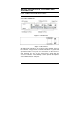
switch for 1 to 4 port to adjust link mode with other network devices. Another 4 ports use auto-negotiation protocol only. There are three type of link mode can be chosen, Autonegotiation, 100Mbps/Full duplex and 10Mbps/Full duplex. Port 1 Port 2 Port 3 ON adjustable DIP Sw itch for ports Port 1 to Port 4 Port 4 Port 1 Port 3 1 2 3 4 5 6 7 8 Port 5 Port 2 Port 6 Port 4 OFF Port 7 Full Duplex Port 8 10M Auto1 2 100M negotiation Figure 1-5.
DES-121T Gigabit 1000Base-T Switch Module Figure 3. Gigabit 1000Base-T Switch Module Front View DES-121T Gigabit 1000Base-T Switch Module Features Compliant Gigabit Media Independent Interface (GMII ) 1 X 100/1000Mbps N-Way auto-negotiation switch port Automatic MDI crossover function Up to 2.
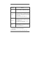
ACT This LED indicator blinks green when the port is transmitting or receiving packets. When the device is not attached, the LED indicator is not lit. LK100 The LED indicator is green when the Port is linking with 100Mbps mode. When the port is operating in 10Mbps mode or not connected, the LED indicator is not lit. FD The LED indicator is yellow when the port is operating in Full-duplex mode. When the port is operating in Halfduplex mode, the LED indicator is not lit.
DES-124F 4 Ports 100Base-FX Fiber Module Figure 1-8. 4 port 100Base-TX/FX Front View When installed into a DES-1200M , the DES-124F Module provides 4 x 100Mbps Fast Ethernet fiber ports which can be used to: Connect the DES-1200M to the backbone of your network; that is, to a basement switch, hub or router. Connector the DES-1200M to a 100Mbps server or end station. An ST (or SC) connector provides the link to the multi-mode fiber cabling and three LEDs show five status of the Module ata glance.
The following Table1-3. lists the ports operating modes based on the DIP switch position. PORT 1 PORT 2 PORT3 PORT4 SW 1 2 3 4 ON Half-Duplex Half-Duplex Half-Duplex Half-Duplex OFF Full-Duplex Full-Duplex Full-Duplex Full-Duplex Table 1-3. 4 ports 100Base-FX Fiber Module DIP switch functions DES-124F 4 ports 100Base-FX Fiber Module Feature Conforms to IEEE 802.
DES-121G/GL 1000Base-SX/LX Fiber Module Figure 1-10. 1000Base-SX/LX Front View When installed into a DES-1200M, the DES-121G/GL 1000Base-SX/LX Module provides 1 Gigabit Ethernet ports which can connect the DES-1200M to a Gigabit Backbone Switch or Server with Gigabit NIC. DES-121G/GL 1000Base-SX/LX Fiber Module Features Conforms to IEEE 802.3z draft 4.2 and 802.
C HAPTER 2 P LANNING YOUR N ETWORK Before you install your DES-1200M, you should review the guidelines for setting up Ethernet networks. Further, you should plan your network to take maximum advantage of its switching capabilities. 10Base-T Ethernet Network Guidelines The maximum length of a 10Base-T cable segment is 100 meters (328 feet). The maximum number of nodes on a 10Base-T segment is one (1) for regular 10Base-T. The recommended cable type is EIA/TIA Category 3 or higher.
The maximum network diameter is 200 meters (656 feet) when using Class I hubs and 205 meters (672.5 feet) when using Class II hubs. 100Base-FX Fast Ethernet Network Guidelines In Multi-mode, the fiber optic segment cannot exceed 2 km (62.5/125µm), 2 km (50/125µm) in length. In Single-mode, the fiber optic segment cannot exceed 60km (9/125µm) in length. 1000BASE-SX and LX Network Guideline 1000BASE-SX In Multi-mode, the fiber optic segment cannot exceed 220m (62.5/125µm) or 500m (50/125µm) in length.
Network Planning Using a switch, such as a 4-Slot Modular Switch, can expand network topologies and enhance network performance. Each port on a switch connects to a separate network with its own collision domain. Separating networks with these switches allows you to expand 10Base-T networks past the four-hub limit and expand 100Base-TX networks past the one or two hub limit. These switches also filter incoming traffic.
network with four hubs to your 4-Slot Modular Switch. Then you can connect another 10Base-T network with four hubs to your 4-Slot Modular Switch. You will then have one network with two collision domains, allowing four hubs on each port. Figure 2-1. Expanding your 10Base-T Network 100Base-TX Networks The hub limit of a 100Base-TX network depends on the class of the hub in the network. With a Class I hub, the network is limited to one hub. With a Class II hub, the network is limited to two hubs.
Figure 2-2. Expanding your 100Base-TX network (Class I) Collapsed Backbone Link Traditionally, bridges and routers have been used to link local area networks into one interconnected network. But these devices involve difficult management and long traffic delays. The 4-Slot Modular Switch providers multiport bridges with short delays, easy setup and maintenance, making it ideal for backbone links.
collapsed backbones. Figure 2-3.
Fileserver Link 100Base Solution With a fileserver link, you can increase file server performance by increasing the Hub's bandwidth between one or more fileservers and the workgroups they serve. If you connect 10Mbps workgroup hubs to the 10Mbps ports on the 4-Slot Modular Switch, traffic in one workgroup will not interfere with the performance of another workgroup. Figure 2-4.
Connecting servers through 100Base-TX ports increases performance to the clients, even if the clients are on 10Base-T segments. Because multiple 10Base-T devices can access the file server at the same time through a 100Base-TX connection, performance increases to beyond the performance of standard 10Base-T or 100Base-TX hubs.
Figure 2-5. Used as a Multiport Bridge Using your hub, you can also connect 10Base-T networks and 100Base-TX and 1000Base-SX/LX networks together for more flexibility in your network topology. As in the Figure 16 shown above, the 4-Slot Modular Switch can connect through one port to a 10Base-T network, and through another port, connect to a 100Base-TX port, creating one network. This switch can also connect to a 1000 Base-LX or SX port.
C HAPTER 3 I NSTALLATION The DES-1200M can be installed quickly and easily. However, for an installation with minimum impact on the existing network, please read this chapter carefully. Installing a DES-1200M involves three steps: 1. Choosing a location 2. Supplying power 3. Connecting the switch Choosing A Location The location of the switch is based on the following criteria: Avoid dusty locations.
Figure 3-1. Attaching self-adhesive feet for desktop installation Rack Installation Your switch comes with two rack mounting brackets. you can use these brackets to mount the switch on an EIA standard 19" rack. Attach the brackets to the switch, using the screws provided. Figure 3-2. Attaching the mount brackets for rack installation Next, install the switch in the rack using the screws provided to attach the brackets to the rack.
Supplying Power The DES-1200M is equipped with a universal switching power supply that accepts AC input voltages from 100 to 240VAC and 50 to 60 Hz. To supply power to your switch: 1. Plug the connector of the power cord into the power port on the rear panel of your switch. 2. Plug the other end of the power cord into an AC wall outlet. 3. Set the power switch to ON and verify that the Power LED is lit. If it is not, check the following: The power switch is in the ON position.
C HAPTER 4. M ODULE I NSTALLATION AND R EMOVAL WARNING Before installing the Modules into the DES-1200M, you must disconnect the Switch from the main power supply. Handling the Modules The Module can be easily damaged by electrostatic discharge. To prevent damage, please observe the following: Do not remove Modules from their packaging until you are ready to install it into a Switch. Do not touch any of the pins, connections or components on the Modules.
DES-1200M and to aid the circulation of cooling air. 4. Hold the Module so that the text on the front panel is oriented correctly, and insert it into the DES-1200M, ensuring the connectors are fully engaged. Tighten the two captive thumbscrews that secure the Module in place. Figure 4-1. Insert the module Installing the Modules Installing 10/100Base-TX Modules a. Insert the RJ-45 connector on your cable into the socket of the Module. b.
appropriate device fitted with a 100Mbps adapter. Check the LED indicators on the front of the Switch to ensure that the Module is operating correctly. Installing 1000Base-SX/LX Modules a. Remove the protective plastic covers from the fiber connectors on the Module. b. Ensure that the Switch is powered up. c. Plug the SC connector on the fiber cable into the fiber socket on the Module. d. Connect the other end of the fiber optic segment to an appropriate device fitted with a 1000Mbps adapter. e.
A PPENDIX A. T ECHNICAL S PECIFICATIONS Compatibility with Ethernet Standards: The DES-1200M has been designed in accordance with IEEE Standard 802.3, 802.3u, 802.3z .
Physical Characteristics: Buffer Size 5 Mbytes memory share per 10/100Base-TX module, maxi 20 Mbytes per unit 5 Mbytes memory share per 100Base-FX module, maxi 20 Mbytes per unit.
A PPENDIX B. P IN A SSIGNMENTS RJ-45 station ports can be attached to any device which use a standard network interface (e.g., a workstation, server, bridge or router). RJ-45 daisy-chain ports can be cascaded to a station port on similar networking devices (e.g., another switch or hub). Use unshielded twisted-pair (UTP) for RJ-45 connections: 100 ohm Category 3,4 or 5 cable for 10Mbps connections or 100 ohm Category 5 cable for 100Mbps connections.
are shown below.
FCC Certifications This equipment has been tested and found to comply with the limits for a Class A digital device, pursuant to part 15 of the FCC Rules. These limits are designed to provide reasonable protection against harmful interference when the equipment is operated in a commercial environment. This equipment generates, uses, and can radiate radio frequency energy and, if not installed and used in accordance with the instruction manual, may cause harmful interference to radio communications.
LIMITED WARRANTY D-Link provides this limited warranty for its product only to the person or entity who originally purchased the product from D-Link or its authorized reseller or distributor.
software that substantially conforms to D-Link’s functional specifications for the Software. Except as otherwise agreed by D-Link in writing, the replacement Software is provided only to the original licensee, and is subject to the terms and conditions of the license granted by D-Link for the Software. The Warranty Period shall extend for an additional ninety (90) days after any replacement Software is delivered.
Products that have been subjected to abuse, accident, alteration, modification, tampering, negligence, misuse, faulty installation, lack of reasonable care, repair or service in any way that is not contemplated in the documentation for the product, or if the model or serial number has been altered, tampered with, defaced or removed; Initial installation, installation and removal of the product for repair, and shipping costs; Operational adjustments covered in the operating manual for the product, and normal
GOVERNING LAW: This Limited Warranty shall be governed by the laws of the state of California. Some states do not allow exclusion or limitation of incidental or consequential damages, or limitations on how long an implied warranty lasts, so the foregoing limitations and exclusions may not apply. This limited warranty provides specific legal rights and the product owner may also have other rights which vary from state to state. Wichtige Sicherheitshinweise 1.
b – Flüssigkeit ist in das Gerät eingedrungen. c – Das Gerät war Feuchtigkeit ausgesetzt. d – Wenn das Gerät nicht der Bedienungsanleitung ensprechend funktioniert oder Sie mit Hilfe dieser Anleitung keine Verbesserung erzielen. e – Das Gerät ist gefallen und/oder das Gehäuse ist beschädigt. f – Wenn das Gerät deutliche Anzeichen eines Defektes aufweist. 16. Bei Reparaturen dürfen nur Orginalersatzteile bzw. den Orginalteilen entsprechende Teile verwendet werden.
Offices AUSTRALIA CANADA CHILE CHINA DENMARK EGYPT FRANCE GERMANY INDIA ITALY JAPAN RUSSIA SINGAPORE S. AFRICA SWEDEN TAIWAN D-LINK AUSTRALIA Unit 16, 390 Eastern Valley Way, Roseville, NSW 2069, Australia TEL: 61-2-9417-7100 FAX: 61-2-9417-1077 TOLL FREE: 1800-177-100 (Australia), 0800-900900 (New Zealand) URL: www.dlink.com.au E-MAIL: support@dlink.com.au, info@dlink.com.
U.K. U.S.A. TEL: 886-2-2910-2626 FAX: 886-2-2910-1515 URL: www.dlinktw.com.tw E-MAIL: dssqa@tsc.dlinktw.com.tw D-LINK EUROPE 4th Floor, Merit House, Edgware Road, Colindale, London, NW9 5AB, U.K. TEL: 44-20-8731-5555 FAX: 44-20-8731-5511 URL: www.dlink.co.uk E-MAIL: info@dlink.co.uk D-LINK U.S.A. 53 Discovery Drive, Irvine, CA 92618 USA TEL: 1-949-788-0805 FAX: 1-949-753-7033 INFO LINE: 1-800-326-1688 BBS: 1-949-455-1779, 1-949-455-9616 URL: www.dlink.com E-MAIL: tech@dlink.com, support@dlink.
Registration Card Print, type or use block letters. Your name: Mr./Ms _____________________________________________________________________________ Organization: ________________________________________________ Dept.
Retail/Chainstore/Wholesale Government Transportation/Utilities/Communication VAR System house/company Other________________________________ 9. Would you recommend your D-Link product to a friend? Yes No Don't know yet 10.