DES-3204 4-Port Gigabit Ethernet Switch D-View Management Module User’s Guide
Copyright Statement Copyright ©1999 D-Link Corporation No part of this publication may be reproduced in any form or by any means or used to make any derivative such as translation, transformation, or adaptation without permission from D-Link Corporation/D-Link Systems Inc., as stipulated by the United States Copyright Act of 1976. Trademarks D-Link is a registered trademark of D-Link Corporation/D-Link Systems, Inc. All other trademarks belong to their respective owners.
Table of Contents ABOUT THIS GUIDE .......................................................................................2 INTRODUCTION..............................................................................................3 DGS-3204 INTELLIGENT ETHERNET SWITCH .....................................................3 NETWORK MANAGEMENT ..................................................................................3 INSTALLING THE MANAGEMENT MODULE..........................................
DGS-3204 Ethernet Switch Management User’s Guide DGS-3204 Management User’s Guide About this Guide This User’s Guide tells you how to use the D-View network management system (version 4.1 or later) to manage your DGS-3204 intelligent Gigabit Ethernet switch, including how to install the D-View management module for the switch, and how to use the module to control and monitor the switch.
DGS-3204 Ethernet Switch Management User’s Guide Introduction DGS-3204 Intelligent Ethernet Switch This guide discusses how to manage the DGS-3204 switch using the D-View network management system. The DGS-3204 combines conventional Ethernet, Gigabit Ethernet and switching technologies into one package. This device features four ultra high-speed 1000BASE-SX Gigabit Ethernet switching ports supporting.
DGS-3204 Ethernet Switch Management User’s Guide A network protocol known as the Simple Network Management Protocol (SNMP) is generally used to communicate between network management stations and the devices they manage. SNMP was originally developed for controlling the devices that made up the infrastructure of the Internet, and has become the primary standard for network management. SNMP commonly runs “on top of” the TCP/IP Internet Protocol, though other transmission methods are possible.
DGS-3204 Ethernet Switch Management User’s Guide Installing the Management Module This section describes the requirements and procedures for installing the DGS3204 management module on your network management system. Requirements We recommend that your system meet the following requirements to be able to use the DGS-3204 switch management module: ♦ A PC-compatible computer with a 486DX2-66 or faster processor ♦ Microsoft Windows version 3.1x or Microsoft Windows 95 or later operating system.
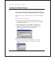
DGS-3204 Ethernet Switch Management User’s Guide Installing the Module Software Note: Please ensure that the D-View platform program has been installed on the computer you are using for network management before proceeding. Take the following steps to install the module on your network management system: 1. Exit D-View if you are running it. 2.
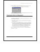
DGS-3204 Ethernet Switch Management User’s Guide 6. The installation program will install all of the necessary files onto your system. When it is finished, it will display the following dialog: Click on the Exit button. The D-View network management system is now ready to manage DGS-3204 Ethernet switches.
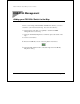
DGS-3204 Ethernet Switch Management User’s Guide DGS-3204 Management Adding your DGS-3204 Switch to the Map Before you can manage individual DGS-3204 Ethernet switches, you need to add them to your D-View network map. You can do this either by: ♦ Using D-View’s Auto Discover capability to add all new SNMPmanageable devices to the map. ♦ Using the Add-Modify Map Device command to place each switch on the map. To use the second method: 1. Press the Add/Modify a device on the map button shown below. 2.
DGS-3204 Ethernet Switch Management User’s Guide 3. Give the switch a name, and enter its IP address and SNMP community names. 4. Click on New. The DGS-3204 switch icon should now be displayed on your network map as shown below.
DGS-3204 Ethernet Switch Management User’s Guide The Module Display Double-clicking on the icon in the network map causes the module display to open. The module display is used to monitor and perform network management functions on the selected device. The module display for the DGS-3204 appears as follows: ♦ Menu Buttons The Configuration, Monitor, Reset, and Help buttons display their respective pull-down menus. The items listed in these menus are described later on in this manual.
DGS-3204 Ethernet Switch Management User’s Guide ♦ Error Status Line This line displays messages describing errors that occur when the module is unable to obtain information it needs. When an error occurs, a red border appears around the error status line. ♦ Ports Each of the 1000BASE-SX ports on the front panel are depicted. You can select individual ports to perform operations on them. Clicking on the gray area immediately surrounding the ports will deselect the port and select the switch as a whole.
DGS-3204 Ethernet Switch Management User’s Guide tables used in management. The section below addresses the function and use of each item in the menu button’s drop-down menus. Configuration Menu Button The Configuration menu contains options that allow you to get information about current settings, configure switch parameters and setup the switch for monitoring.
DGS-3204 Ethernet Switch Management User’s Guide The values in the window that are displayed in black can be changed either in the D-View management module or by using the console program; values in blue are fixed either by the hardware or by the switch’s firmware. Clicking on the Set button allows you to configure settings for the switch, and opens the Set Configuration window described later in this manual.
DGS-3204 Ethernet Switch Management User’s Guide ♦ SysUpTime The amount of time that the switch has been powered on, or since the last time the switch was reset. ♦ SysName A user-assigned name for the switch. Information on changing this setting can be found in the Set Configuration section below. ♦ SysLocation A user-assigned description for the physical location of the switch. Information on changing this setting can be found in the Set Configuration section below.
DGS-3204 Ethernet Switch Management User’s Guide ♦ Out-Of-Band Baud Rate Displays the baud the RS232 port is set to operate at. ♦ Software Update Mode Displays whether the switch is setup to download new software from a TFTP server on the Network, or directly from a SLIP server. ♦ Last Boot Server address Displays the last IP Address used when using BootP or TFTP to boot up the server. ♦ Boot Server Address Displays the IP Address of the server currently used to boot up the switch.
DGS-3204 Ethernet Switch Management User’s Guide Port Information Choosing the first item – Information - in the Configuration menu when an individual port is selected (colored blue) causes the following window to open: Tip: Double-clicking on the port will also cause the above window to open.
DGS-3204 Ethernet Switch Management User’s Guide ♦ Speed/Duplex Displays the current speed and duplex settings for the port. All ports on the DGS-3204 can only be set to run at 1Gbps (1000Mbps) at Full duplex. ♦ Admin State When you disable the Admin State, the port will be partitioned from the rest of the network. In this partitioned state, it will only be able to accept management packets. All other packets will be dropped.
DGS-3204 Ethernet Switch Management User’s Guide Switch Configuration Choosing the second item – Set Configuration - in the Configuration menu when the switch is selected (an individual port is not selected) causes the following window to open. There are four tabs running along the top – General, Console, Servers, Advanced – which allow you to configure a number of settings for the switch.
DGS-3204 Ethernet Switch Management User’s Guide Console The Console tab of the Network Configuration dialog allows you to set parameters for the Diagnostics RS232 port located on the front of the switch. Each field is described below: ♦ RS-232 Port Used As Sets the Diagnostic RS232 port to either Console or SLIP. The Console setting allows the port to be used for terminalbased console management. The SLIP setting configures the RS232 port for SLIP communications.
DGS-3204 Ethernet Switch Management User’s Guide Each item is described below: ♦ TFTP Server This box should contain the IP address of the TFTP server, if any, you are using on your network. ♦ Software Update Mode Defines the method you wish to use to upload new runtime switching software onto the switch.
DGS-3204 Ethernet Switch Management User’s Guide ♦ Configuration File This field should contain the complete path and filename for the configuration file you wish to use to upload settings to this switch. ♦ Enable BootP On Startup When checked (!), the server will utilize the BootP protocol to get its IP address, subnet mask and gateway IP the next time it is restarted or rebooted.
DGS-3204 Ethernet Switch Management User’s Guide and will not age out. When Disabled, the automatic learning function of the switch will be turned on. ♦ Spanning Tree Protocol Enables/Disables Spanning Tree on the switch. ♦ Head Of Line (HOL) Blocking Prevention Enables/Disables Head-OfLine Blocking on the switch. For more detailed explanations, please refer to the Port Configuration section below.
DGS-3204 Ethernet Switch Management User’s Guide ♦ Flow Control State Enables or disables IEEE 802.3x flow control on the port. Flow control allows the port to send a Pause packet to a transmitting IEEE 802.3x-compliant device, so that it’s buffers don’t overflow and data is not lost. ♦ Lock State When locked, automatic learning for all stations connected to this port will stop and entries in the Forwarding Table for all devices residing on this port will age out.
DGS-3204 Ethernet Switch Management User’s Guide can be configured to Do Nothing, Forward or Forward and Trap. The Do Nothing setting causes the switch to operate normally, in other words, ignore the situation. If the port had met the Broadcast Storm Rising Action criteria and started Blocking broadcast packets, it will continue doing so. The Forward setting causes the port to begin forwarding broadcast frames, thus removing the Blocking state imposed by the Broadcast Storm Rising Action.
DGS-3204 Ethernet Switch Management User’s Guide IP Interfaces IP parameters can be viewed and changed from the management modules when necessary. After changing the IP address, your connection to the switch will be cut off. Change the settings in the D-View map by selecting the DGS-3204 icon in the map and clicking on the Add/Modify a device on the map button (shown below) to update the IP address to the new setting.
DGS-3204 Ethernet Switch Management User’s Guide ♦ Default Gateway IP Shows the IP Address of the gateway router where packets destined for IP addresses outside of the local network should be sent for forwarding. ♦ Phys Address Shows the physical (MAC) address of the switch. ♦ If Type Describes the type of IP Interface. The DGS-3204 supports CSMA/CD the standard Ethernet protocol. To change the switch’s IP settings, press the Modify button in the IP Interface Table window.
DGS-3204 Ethernet Switch Management User’s Guide The switch requires you to designate the network management stations that will receive these traps. To view the trap recipients, select Trap Receivers from the Configuration menu. The fields displayed are: ♦ Entry Status Shows whether or not this entry is valid. ♦ Manager IP Address The IP address of the trap recipient. ♦ Community Shows the SNMP community name that will be used for the traps sent to this recipient.
DGS-3204 Ethernet Switch Management User’s Guide When all changes have been made, click on the Add button if adding a new entry, or click on the Modify button when modifying an existing entry. For more information about changing the switch’s trap configuration, see the DGS-3204 hardware User’s Guide. Port Mirroring The DGS-3204 allows you to mirror traffic on one port to another port for analysis.
DGS-3204 Ethernet Switch Management User’s Guide Static Fwd Table The Static Forwarding Table allows you to assign permanent forwarding criteria for specific MAC addresses. Thus, whenever the switch receives a packet destined for a MAC address in the table, it will always be forwarded to the associated port. To view the Static Forwarding Table, select Static Fwd Table from the Configuration menu.
DGS-3204 Ethernet Switch Management User’s Guide The fields displayed are: ♦ MAC Address The MAC Address for the device you wish to create a static forwarding entry for. ♦ Port The port through which packets destined for the MAC address will always be forwarded. When all changes have been made, Click Apply to let the change take effect. Filtering Table To prevent a particular machine from accessing the network, you can filter that machine's MAC address by entering it in the filtering table.
DGS-3204 Ethernet Switch Management User’s Guide ♦ Filter Conditions Automatically set by the DGS-3204 to Destination and Source, meaning that all packets having a destination or source MAC address defined in the MAC Address field will be dropped. To remove an entry from the Filtering Table, simply click on the desired entry so that it is highlighted and then click on the Delete button on the right side of the window.
DGS-3204 Ethernet Switch Management User’s Guide Port Statistics The module allows you to display four network statistics: ♦ Port Utilization ♦ Traffic ♦ Errors ♦ Packet Analysis Except for Port Utilization, Ethernet statistics for a given port can be displayed in: ◊ table form, ◊ line curve form, or ◊ bar graph form. You can display statistics for a particular port by selecting that port and choosing the appropriate Monitor menu item.
DGS-3204 Ethernet Switch Management User’s Guide ♦ Good Frames Received (Frames Rx) Counts all valid frames received on the port. ♦ Total Frames Rx Counts the total number of frames received on the port, whether valid or invalid frames. ♦ CRC Error Counts frames that fail the CRC frame integrity check. CRC errors are usually indicative of hardware problems.
DGS-3204 Ethernet Switch Management User’s Guide ♦ Frames 64Bytes Displays the number of frames with 64 bytes of information. ♦ Frames 65~127Bytes Displays the number of frames with 65 to 127 bytes of information. ♦ Frames 128~255Bytes Displays the number of frames with 128 to 255 bytes of information. ♦ Frames 256~511Bytes Displays the number of frames with 256 to 511 bytes of information. ♦ Frames 512~1023Bytes Displays the number of frames with 512 to 1023 bytes of information.
DGS-3204 Ethernet Switch Management User’s Guide Port Traffic This display permits you to observe the network traffic on each individual port. Select the port that you wish to display statistics for. To display the Port Traffic: 1. Choose Monitor from the main menu. 2. Choose Traffic from the Monitor menu. 3. Choose Table from the Traffic menu. The Port Traffic Table will be displayed.
DGS-3204 Ethernet Switch Management User’s Guide Choose Curve from the Traffic menu and the Port Statistics Traffic Line Curve will be displayed. Choose Bar from the Traffic menu and the Port Statistics Traffic Bar Graph will be displayed.
DGS-3204 Ethernet Switch Management User’s Guide Port Errors This display permits you to observe the various errors on each individual port. Select the port that you wish to display statistics for. To display the Port Errors: 1. Choose Monitor from the main menu. 2. Choose Port Statistics from the Monitor menu. 3. Choose Errors from the Port Statistics menu. Choose Table from the Errors menu. The Port Errors table will be displayed.
DGS-3204 Ethernet Switch Management User’s Guide Choose Curve from the Errors menu. The Port Statistics Errors Line Curve will be displayed. Choose Table from the Errors menu. The Port Errors table will be displayed.
DGS-3204 Ethernet Switch Management User’s Guide Packet Analysis This display permits you to observe the frequency that different types of packets arrive at an individual port. Select the port that you wish to display observe. To display the Packet Analysis: 1. Choose Monitor from the main menu. 2. Choose Port Statistics from the Monitor menu. 3. Choose Packet Analysis from the Port Statistics menu. 4. Choose Table from the Packet Analysis menu. The Packet Analysis table will be displayed.
DGS-3204 Ethernet Switch Management User’s Guide Choose Curve from the Packet Analysis menu. The Port Statistics Packet Analysis Line Curve will be displayed. Choose Bar from the Packet Analysis menu. The Port Statistics Packet Analysis Bar Graph will be displayed.
DGS-3204 Ethernet Switch Management User’s Guide Reset Menu Button Resetting the switch will restart the switch using any new configuration settings that have been saved. It also resets all counters and tables. Save Changes When configuration settings are changed using the Apply button in the various windows, the changes will take effect until the switch is reset or powered off. Using the Save Changes feature writes the settings onto flash memory in the switch thereby becoming the new default settings.
DGS-3204 Ethernet Switch Management User’s Guide Click Save to save all changes made to configuration settings in the switch. Reset The management module allows you to reset the switch remotely. Doing a reset is equivalent to turning the switch off and on again, which resets all statistic counters and restores settings to the values stored in flash memory. To perform a reset, 1. Click on the Reset menu button. 2. Choose Reset from the drop-down menu.
DGS-3204 Ethernet Switch Management User’s Guide Click Reset to initiate a system reset.
DGS-3204 Ethernet Switch Management User’s Guide Index A D Add MAC Static Forwarding Table Entry........................................ 29 Add/Modify a device on the map7, 24 Admin State.......................... 16, 22 Advanced.................................... 20 agent ............................................. 2 Default Gateway IP .....................25 Destination and Source ...............31 Dropped Frames..........................34 B Block ..........................................
DGS-3204 Ethernet Switch Management User’s Guide G General ....................................... 18 Good Bytes Received (Bytes Rx)33 Good Bytes Sent (Bytes Tx)....... 33 Good Frames Received (Frames Rx) .......................................... 33 Good Frames Sent (Frames Tx) . 33 H Head Of Line (HOL) Blocking Prevention ............................... 21 Head-of Line blocking................ 23 HOL State....................... 15, 17, 23 I IF Index ...................................... 25 If Type.....
DGS-3204 Ethernet Switch Management User’s Guide R Requirements................................ 4 Reset........................................... 43 Reset Menu Button..................... 42 RS232 Port Used As................... 14 RS-232 Port Used As ................. 19 Runtime Software Version ......... 13 S Save Changes ............................. 42 Send Authentication Fail Trap.... 18 Servers........................................ 19 Set Configuration .......................