DES-3224 10/100 Auto Negotiation Switch User’s Guide Rev. A1 (December, 1998) 6DES3224..
D-Link Limited Warranty Hardware: D-Link warrants its hardware products to be free from defects in workmanship and materials, under normal use and service, for the following periods measured from date of purchase from D-Link or its authorized Reseller: Product Type Warranty Period Complete Products One year Spare parts and spare kits 90 days Your dealer, or your nearest D-Link office, can advise whether a longer period of warranty applies to your purchase, and if so, can provide you a separate certif
D-Link’s sole obligation under this software warranty shall be to replace any defective software product with product that substantially conforms to D-Link’s applicable product documentation. You assume responsibility for the selection of appropriate application and system/platform software and associated reference materials.
No part of this publication may be reproduced in any form or by any means or used to make any derivative such as translation, transformation, or adaptation without permission from D-Link Corporation/D-Link Systems Inc., as stipulated by the United States Copyright Act of 1976. FCC Warning This equipment has been tested and found to comply with the limits for a Class A digital device, pursuant to Part 15 of the FCC Rules.
Wichtige Sicherheitshinweise Bitte lesen Sie sich diese Hinweise sorgfältig durch. Heben Sie diese Anleitung für den spätern Gebrauch auf. Vor jedem Reinigen ist das Gerät vom Stromnetz zu trennen. angefeuchtetes Tuch zur Reinigung. Vervenden Sie keine Flüssig- oder Aerosolreiniger. Am besten dient ein Um eine Beschädigung des Gerätes zu vermeiden sollten Sie nur Zubehörteile verwenden, die vom Hersteller zugelassen sind. Das Gerät is vor Feuchtigkeit zu schützen.
Table of Contents Table of Contents...................................................................................................................i About This Guide..................................................................................................................1 Audience...........................................................................................................................1 Organization...................................................................................
LEDs...................................................................................................................................12 DES-3224 LED Panel......................................................................................................13 Speed/ Link/ Activity LED ..........................................................................................13 5...................................................................................................................................
Spanning Tree Configuration Menu.............................................................................40 SNMP Management Configuration..................................................................................43 SNMP Management Configuration Menu....................................................................43 VLAN Port Management.................................................................................................47 VLAN Port Management Menu....................................
10/100 Auto Negotiation Switch User’s Guide About This Guide This section defines the scope of this guide and gives a summary of the contents of each chapter. It describes the features of the D-Link DES-3224 10/100 Auto Negotiation Switch. Information about the DES-3224 and other D-Link products is available on our web site at www.dlink.com. Audience This user guide is intended for the networking or computer technician who is installing the DES-3224 on a network.
10/100 Auto Negotiation Switch User’s Guide 1 Introduction This chapter gives a physical and functional overview of the DES-3224. The DES-3224 is an intelligent, managed switch, designed for use on medium sized networks as part of the backbone or for use with other switches and hubs on a larger network. The chapter is divided into the following sections. Each section briefly describes the features of the DES-3224. Most of the topics discussed will be explained in greater detail later in the manual.
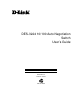
10/100 Auto Negotiation Switch User’s Guide The MDI-II port is used as an uplink port for connecting to another switch or for connecting to hubs. LED Panel MDI-Uplink port MDI-X ports Figure 1: DES-3224 Front Panel All 24 MDI-X ports on the DES-3224can be used for network connections. You cannot use both the MDI-II Uplink port and port 1x simultaneously. The RS-232 port is located at the rear of the DES-3224. All LEDs are located on the front panel of the DES-3224.
10/100 Auto Negotiation Switch User’s Guide There are heat vents located on the side opposite the fans. The fans and the vents help to cool the DES-3224. Always leave two inches of space around the DES-3224 so that air can circulate and cool the DES-3224. Rear Panel The three pronged power plug, female RS-232 Console port and rear fan are located at the rear of the DES-3224, displayed in Figure 3.
10/100 Auto Negotiation Switch User’s Guide Updating Firmware Firmware can be updated quickly and easily. See the section Software Update Menu, Chapter 5, for instructions on updating firmware.
10/100 Auto Negotiation Switch User’s Guide 2 Installing the DES-3224 This chapter covers the following: • Unpacking the DES-3224 • Installation options and instructions • Powering on the DES-3224 Unpacking the DES-3224 Open the box and carefully unpack the DES-3224. You should have all the items on the following checklist: • DES-3224 10/100 Auto Negotiation Switch • RS-232 DCE serial cable • Two mounting brackets and eight screws • Four rubber pads with adhesive backing • One six foot (1.
10/100 Auto Negotiation Switch User’s Guide Desktop/ Shelf Installation Follow these steps to install the DES-3224 on a desktop or shelf: 1. Place the four rubber pads at the four corners of the DES-3224. 2. Install the DES-3224 on the desktop/shelf where you would like to place it. Rack Installation The DES-3224 can be mounted in an EIA standard size, 19 inch rack. The dimensions of the DES-3224 are 17.4 x 10.4 x 2.48 inches. The DES-3224 can be placed in a wiring closet along with other equipment.
10/100 Auto Negotiation Switch User’s Guide 3 Connecting the DES-3224 to the Network This chapter covers the following: • Cable Specifications • Ports • Connecting the DES-3224 to another DES-3224 • Connecting the DES-3224 to other switches and hubs This section deals with making cables and connecting the DES-3224 to other devices.
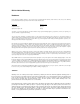
10/100 Auto Negotiation Switch User’s Guide must use the correct pin arrangement in order for the DES-3224 to work properly. See Figure 4 for an example of straight through and crossover cable. Table 2: Cable Requirements shows the cable specifications. Figure 4: Cable Diagram Table 2: Cable Requirements Ethernet Type Cable Required Cable Length 10BASE-T Category 3, 4, or 5 STP/UTP cable 100 m (328 ft.) 100BASE-TX Category 5 STP/ UTP cable 100 m (328 ft.
10/100 Auto Negotiation Switch User’s Guide Ports There are three types of ports on the DES-3224: MDI-II Uplink, MDI-X and RS-232. The difference between the MDI-II Uplink port and the MDI-X ports is the internal pin arrangement. MDI-II Port An MDI-II port is a straight through port. The pin arrangement is the same as the pin arrangement of a straight through cable. MDI-X Port MDI-X ports are crossover ports. The pin arrangement is the same as the arrangement in a crossover cable.
10/100 Auto Negotiation Switch User’s Guide DES-3224 to DES-3224 Connection There are two ways to connect DES-3224s together: MDI-II uplink port or MDI-X ports. See Table 3: Cable Connections for the proper connections to use with each type of port. The DES-3224 is also compatible with the DES-5016 and DES-5024. Port Trunking can be configured on the device if more than one port is connected between two DES-3224s or if more than one ports is connected between a DES-3224, DES-5016 and DES-5024.
10/100 Auto Negotiation Switch User’s Guide 4 LEDs The LED panel of the DES-3224, displayed in Figure 5, is designed to allow you to manage the DES-3224 at a glance. The LEDs indicate the following: • Power • Speed • Link • Activity • Duplex mode • CPU utilization and error status All of the LEDs are described in detail. Use the tables to determine the meaning of each LED. Power LED The DES-3224 has a power LED. The power LED lights when the DES-3224 is plugged in.
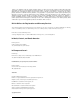
10/100 Auto Negotiation Switch User’s Guide DES-3224 LED Panel The LED panel of the DES-3224 displayed in Figure 5, allows you to manage the DES-3224 at a glance. 10Mbps 100 Mbps Link Power Full Act Half Utilization Figure 5: DES-3224 LED Panel Speed/ Link/ Activity LED The 10/100 Mbps, Link, and Activity are combined into one LED. See Table 5: DES-3224 Speed/ Link/ Act LED. All ports auto negotiate the proper speed and duplex mode when a cable is plugged in.
10/100 Auto Negotiation Switch User’s Guide Table 6: DES-3224 Full/ Half LED Status Color Meaning On Green Port is in Full Duplex Off Dark Port is in Half Duplex Utilization LEDs The Utilization LED indicates the percentage utilization of the CPU during normal operation. The LED increments from left to right. The farther to the right they are, the greater the utilization of the CPU. The first six LEDs are green. The last two are amber.
10/100 Auto Negotiation Switch User’s Guide 5 Managing the DES-3224 This chapter shows the menus used to manage the DES-3224. Three types of management are available on the DES-3224: • Local Console Management (out-of-band) • Telnet Management (in-band) • D-View/ SNMP Management The DES-3224 can be managed in-band or out-of-band. In-band management refers to managing the DES-3224 through the MDI-II uplink port or any of the MDI-X ports. Out-ofband management means going through the RS-232 port.
10/100 Auto Negotiation Switch User’s Guide • • • • Parity: None Stop bits: 1 Flow Control: None Enable: Terminal keys 4. Press Enter to display the login panel. 5. Log in using the default User Name and Password. The User Name and Password are case sensitive. • User Name: D-Link • Default Password: D-Link 5. Press Enter to reach the Main menu. Telnet You can manage the DES-3224 via Telnet session. However, first you must assign a unique IP address to the DES-3224.
10/100 Auto Negotiation Switch User’s Guide Log In The Log In panel, displayed in Figure 6, is the first panel you see when connecting to the DES-3224. All management methods require you to log into the DES-3224 with your user name and password before beginning a management session. For security, you should change the default User Name and Password. Figure 6: Log In Follow these steps to log into the DES-3224 for the first time: Enter the default User Name and Password and press Enter.
10/100 Auto Negotiation Switch User’s Guide Help Message A one page panel, displayed in Figure 7, is available. The menu lists the keystroke and typographic conventions available on the DES-3224.
10/100 Auto Negotiation Switch User’s Guide Panel Conventions Keystroke Conventions Example Description UP, DOWN, or TAB keys Select different items. SPACEBAR Toggle-switch. DEL, or BACKSPACE Remove any input character from thescreen. LEFT or RIGHT keys Move cursor backward or forward. Ctrl-r Refresh Screen Typographic Conventions Example Description :168.8.254.20 Each read only value follows a colon. Each changeable value can be changed only by the toggle switch. [168.8.254.
10/100 Auto Negotiation Switch User’s Guide Console Program The Console Program, shown in Figure 8, is the main menu of the DES-3224. Figure 8: Console Program System Configuration The System Configuration menu gives you general information about the DES-3224 and allows you to assign a LAN IP Address, Subnet Mask, LAN Default Gateway and contact information on the system administrator.
10/100 Auto Negotiation Switch User’s Guide SNMP Management Configuration The SNMP Management Configuration menu allows you to create SNMP Communities and configure SNMP Trap Manager Settings. VLAN Port Management The VLAN Port Management menu allows you to create, delete and modify VLANs quickly and easily. Trunking Port Management The Trunking Port Management menu allows you to create, delete and modify Trunking Ports quickly and easily. Follow these steps to select a menu: 1.
10/100 Auto Negotiation Switch User’s Guide System Information The System Information menu displays the Hardware revision, MAC address, LAN IP address and other information on the DES-3224. System Reset The System Reset menu allows you to reset the DES-3224 through software rather than powering off. Factory Reset to Default Config Values The Factory Reset to Default Config Values menu allows you to reload factory default configurations.
10/100 Auto Negotiation Switch User’s Guide System Information Menu The System Information menu, displayed in Figure 10, allows you to enter management and configuration information on the DES-3224. Figure 10: System Information menu Hardware Revision Specifies the hardware revision and the product generation. Each revision is numbered incrementally. Boot PROM Firmware Version Specifies the version of the Boot PROM being used on the DES-3224. Each version is numbered incrementally.
10/100 Auto Negotiation Switch User’s Guide System Description Brief manufacturer description of the DES-3224. This value cannot be changed. System Name Specifies the full name of the DES-3224. This value can be changed, allowing you to assign a unique name to the DES-3224. You can enter up to 44 characters. System Location Specifies the physical location of the DES-3224, such as a building number or street address. You can enter up to 44 characters.
10/100 Auto Negotiation Switch User’s Guide System Reset The System Reset panel, displayed in Figure 11, enables you to reset the DES-3224 without powering off. Figure 11: System Reset Some configurations will require you to reset the DES-3224 in order for them to take effect. Screen prompts will tell you to reset the DES-3224 in order for them to take effect. Follow these steps to reset the DES-3224: 1. Select Yes. 2. Press Enter. To exit without resetting: 1. Select No. 2. Press Enter.
10/100 Auto Negotiation Switch User’s Guide Factory Reset The Factory Reset panel, displayed in Figure 12, is used to reset the DES-3224 and restore all factory default values. Using this panel erases all configurations and customization. Figure 12: Factory Reset Follow these steps to restore factory default configurations: 1. Select Yes 2. Press Enter. You will see a confirmation panel, displayed in Figure 13. Select Yes to confirm your choice. Select No to return to the System Configuration menu.
10/100 Auto Negotiation Switch User’s Guide Figure 13: Factory Reset Confirmation Follow these steps to exit the panel without restoring factory default parameters: 1. Select No or Exit. 2. Press Enter.
10/100 Auto Negotiation Switch User’s Guide System Rate Control The System Rate Control panel, displayed in Figure 14, allows you to set the packet forwarding rate on the DES-3224. There are two options: Store & Forward and Cut-Through. Figure 14: System Rate Control The DES-3224 can be set for Store and Forward or Cut-Through. This is a global setting that affects all the ports except the RS-232 port.
10/100 Auto Negotiation Switch User’s Guide byte packets are delayed by 1200 microseconds in a Store and Forward device versus 60 microseconds in a Cut-Through device. Store and Forward requires more memory because the DES-3224 must store the packet before sending it out. Advantages of Cut-Through Cut-Through is faster because the packet is sent as soon as the first 128 bytes are received. Cut-Through requires less memory since the DES-3224 only reads the address but does not store the entire message.
10/100 Auto Negotiation Switch User’s Guide Software Update Menu The Software Update menu, displayed in Figure 15, is used to upgrade the software on the DES-3224. Figure 15: Software Update Follow these steps to upload new software: 1. Load the new software to the hard drive of the PC you will be downloading from. Never attempt to load software from the floppy drive. 2. Connect the DES-3224 and the PC with the software on it with the RS-232 cable provided.
10/100 Auto Negotiation Switch User’s Guide Figure 16: Software Update Transfer Figure 17: Send File 5. Select Browse on the panel displayed in Figure 17. The browse option shows the contents of your hard drive. You must specify the path from the DES-3224 to the file the firmware is in. Navigate to the file the firmware is stored in and select it. Use XMODEM to transfer the file. 6.
10/100 Auto Negotiation Switch User’s Guide When the transfer is complete you will see the panel in Figure 18. The DES-3224 will reset itself automatically and you will have to log in again.
10/100 Auto Negotiation Switch User’s Guide User Account Management The User Account Management panels allow you to add users, delete users and modify user access rights. Follow these steps to reach the User Account Management panels: 1. Select User Account Management on the Main menu. 2. Press Enter. User Account Change Menu The User Account Change menu, displayed in Figure 19, allows you to add users, delete users, and modify user rights.
10/100 Auto Negotiation Switch User’s Guide Figure 20: Create New User User Name Enter the user’s name in this field. User names are case sensitive. You can enter a maximum of eight characters. Password Enter the user’s password in this field. Passwords are case sensitive. You can enter a maximum of eight characters. Confirm Password Reenter the user’s password to confirm it in this field. Access Level There are two access levels available on the DES-3224: Super User and General User.
10/100 Auto Negotiation Switch User’s Guide 2. Enter the Password. 3. Reenter the password in the Confirm Password field. 4. Toggle the space bar to set the access level of the new user. 5. Select Save and press Enter. Delete Users The Delete Users panel, displayed in Figure 21, allows you to delete users from the DESDES-3224. As a safety precaution, the DES-3224 will not allow the user who is currently logged in to delete themselves by accident.
10/100 Auto Negotiation Switch User’s Guide Delete Enables you to delete users. The following operations can be performed independently of each other or combined. Follow these steps to change user Access Level: 1. Select the user’s Access Level. 2. Toggle the space bar to change the current Access Level. 3. Select Save and press Enter. Follow these steps to change user Status Level: 1. Select the user’s Status Level. 2. Toggle the space bar to select the new Status Level. 3. Select Save and press Enter.
10/100 Auto Negotiation Switch User’s Guide Change Password The Change Password panel, displayed in Figure 22, enables you to change user passwords. Figure 22: Change Password User Name The name of the user whose password you are going to change. Old Password The user’s old password. New Password The user’s new password. Confirm Password Reenter the new password in this field to confirm it. Follow these steps to change user passwords: 1. Enter the user’s name in the User Name field. 2.
10/100 Auto Negotiation Switch User’s Guide 5. Select Save and press Enter to save your changes. Switch Port Configuration The Switch Port Configuration panels are used to configure individual ports on the DES3224. All three panels are dealt with together. The only difference between the three panels is the port number that they deal with. The options and settings are the same for each. Select the group of ports that you want to configure and then go to the appropriate panel.
10/100 Auto Negotiation Switch User’s Guide Physical Refers to the physical state of the port. If you manually change the state of a port it will remain in that state until you change it. It will not auto negotiate speed and duplex mode. All ports can be in the following physical states: • Auto • 100Tx/Half • 100Tx/Full • 10Tx/Half • 10Tx/Full Ports in the Auto state automatically negotiate speed and duplex mode. This is the default setting.
10/100 Auto Negotiation Switch User’s Guide 2. Enter a new value between zero and 255. 3. Select Save and press Enter. Spanning Tree Configuration The Spanning Tree Configuration panel is used to configure the Spanning Tree Algorithm. The Spanning Tree Algorithm (STA) in the DES-3224 allows you to create alternative paths (using multiple switches or bridges) in your network. These backup paths are idle until the DES-3224 determines that a problem has developed in the primary path.
10/100 Auto Negotiation Switch User’s Guide Spanning Tree Algorithm Spanning Tree Algorithm can be enabled or disabled. Use Spanning Tree to prevent network loops. Bridge Priority The Bridge Priority can be from 0 to 65535. Zero is the highest Bridge Priority. The higher the Bridge Priority the greater the chance that the DES-3224 will be selected as the Root Bridge. The DES-3224 with the highest Bridge Priority is the Root Bridge.
10/100 Auto Negotiation Switch User’s Guide Root Bridge Specifies the MAC address of the Root Bridge. The DES-3224 may or may not be the root bridge. The DES-3224 is the default root bridge. Root Port Specifies the preferred path to the Root Bridge. Only one path per bridge can exist. The default setting is none. Table 7: User Selective STA parameters STA parameters Settings Effects Comment Enable/Disable Enable/ Disable Participate in or remove from STA Enable in a SNMP network.
10/100 Auto Negotiation Switch User’s Guide SNMP Management Configuration The SNMP Management Configuration panel is used to configure the DES-3224 for SNMP management. Leave the default values in place if you are not managing your network through SNMP. The DES-3224 uses the standard MIB-II Management Information Base module. The MIB values can be retrieved from any SNMP based network manager. The DES-3224 supports its own proprietary enterprise as an extended MIB.
10/100 Auto Negotiation Switch User’s Guide Figure 25: SNMP Management Configuration menu SNMP Manager Setting The fields under this setting are used to configure the DES-3224 for SNMP Management. You must configure these fields in order to manage the DES-3224 through SNMP. SNMP Community String The SNMP Community String field allows you to name the SNMP Communities. The names public and private are only default names.
10/100 Auto Negotiation Switch User’s Guide SNMP Trap Manager Setting Enables you to enter the IP addresses of Trap Managers. Traps are messages the DES-3224 sends out to inform trap managers of events on the network. The DES-3224 generates traps and sends them to the network manager. Trap managers are special network users who are given certain rights and access to oversee and maintain the network. This feature is available only in D-View or by using other SNMP management software.
10/100 Auto Negotiation Switch User’s Guide Follow these steps to configure the SNMP Trap Manager Setting: 1. Enter the IP Address of the Trap Manager. 2. Enter the name of the SNMP Community String. 3. Select Status and toggle the space bar to select Valid or Invalid. 4. Select Save and press Enter.
10/100 Auto Negotiation Switch User’s Guide VLAN Port Management A Virtual Local Area Network (VLAN) is a logical subgroup within a LAN that is created with software rather than physical connections. The purpose of a VLAN is to prevent broadcast storms and ease congestion on your network. Each VLAN created is a broadcast domain. A broadcast is a packet that is sent to all nodes on the network. A broadcast domain is a domain in which every node in the domain receives the broadcast packet.
10/100 Auto Negotiation Switch User’s Guide Figure 26: VLAN Port Management menu Follow these steps to create, delete and modify VLAN: 1. Select the appropriate option. 2. Press Enter.
10/100 Auto Negotiation Switch User’s Guide Create/ View VLAN The Create/View VLAN menu, displayed in Figure 27, is used to create a new VLAN. The default value is that all ports belong to one VLAN. You can create up to eight separate VLANs. Ports can belong to two VLANs at the same time. Each VLAN is a broadcast domain. If you have created a trunking group, you must include the entire trunk group in the VLAN. Figure 27: Create New VLAN menu New VLAN Name Is the name of the VLAN you are creating.
10/100 Auto Negotiation Switch User’s Guide All ports will have a status of available on this panel, even after they have been selected as part of a VLAN. There is nothing on this panel that indicates the port is already part of a VLAN. Follow these steps to create a VLAN: 1. Enter the name of the VLAN you are creating. 2. Select the ports you want to include in the VLAN and toggle the space bar to change the status from Available to Selected. 3. Select Save and press Enter.
10/100 Auto Negotiation Switch User’s Guide 4. A screen prompt will warn you that you must reset the DES-3224 in order for the change to take effect. Modify VLAN Menu The Modify VLAN menu, displayed in Figure 29, enables you to modify VLANs. Figure 29: Virtual LAN Name Virtual LAN Name The names of all VLANs appear in this column. Follow these steps to modify VLANs: 1. Select the name of the appropriate VLAN. 2. Press Enter. 3. You will see the VLAN Modify menu, displayed in Figure 30.
10/100 Auto Negotiation Switch User’s Guide Figure 30: VLAN Modify menu Managing the DES-3224 52
10/100 Auto Negotiation Switch User’s Guide Trunking Port Management Menu The Trunking Port Management panels are used to create, delete and modify trunk ports. Figure 31: Trunking Port Management menu Follow these steps to create, delete and modify trunk ports: 1. Select the appropriate option. 2. Press Enter.
10/100 Auto Negotiation Switch User’s Guide Create New Trunking Port The Create New Trunking Port panel, displayed in Figure 32, is used to create Trunk Ports. You can create up to seven trunking groups with up to eight ports in each group. Each Trunking Group acts like a single port. Figure 32: Create New Trunking Port New Trunking Group Name Is the name of the Tunking Group you are going to create. All Trunking Groups must have a name. Port # Is the number of the port.
10/100 Auto Negotiation Switch User’s Guide TrunkGroup. All ports will have a status of available on this panel, even after they have been selected as part of a TrunkGroup. There is nothing on this panel that indicates the port is already part of a TrunkGroup. Follow these steps to create a TrunkGroup: 1. Enter the name of the TrunkGroup. 2. Select the ports you want to include in the TrunkGroup and toggle the space bar to change the status from Available to Selected. 3. Select Save and press Enter.
10/100 Auto Negotiation Switch User’s Guide 3. Select Save and press Enter. Modify Trunking Port The Modify Trunking Port panel, displayed in Figure 34, enables you to Modify Trunking Ports. Figure 34: Modify Trunking Port Trunking Port Name The names of all Trunked Ports appear in this column. Follow these steps to modify Trunked Ports: 1. Select the name of the appropriate Trunked Port. 2. Press Enter. 3. You will see the Modify Trunking Port panel shown in Figure 35.
10/100 Auto Negotiation Switch User’s Guide Figure 35: Trunking Port Modify menu 4. Select the ports that you want to include in the Trunking Group or delete from the Trunking Group. Toggle the space bar to change the current setting. Available means the port is available for inclusion in the Trunking Group. Selected means the port has been selected as part of a Trunking Group. N/A indicates ports that are not available for inclusion in any trunking group. 5.
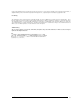
10/100 Auto Negotiation Switch User’s Guide 6 Troubleshooting This troubleshooting section is intended to help you solve the most common problems on the DES-3224. Many problems on the DES-3224 are indicated by the Utilization LED during the powering on process. All LEDs are explained in detail in Chapter 4, LEDs. Error codes are displayed on the Utilization LED. Table 8, System Error LED Indicators, displays the meaning of the error code.
10/100 Auto Negotiation Switch User’s Guide order for them to communicate. Check the speed and duplex setting on both the port and device you are connecting to. Power LED is Off Check the power plug and verify that you are getting power from the wall socket. If the DES-3224 is on, the power LED is not working properly. Return DES-3224. If the DES-3224 is not powering on and power is being received though the wall socket, the power supply is not working. Return the unit.
10/100 Auto Negotiation Switch User’s Guide Table 8: System Error LED Indicators 2 PHY Failure ARL Failure ARL Memory Failure 60 Troubleshooting
10/100 Auto Negotiation Switch User’s Guide A DES-3224 Technical Specifications Switch Specifications • Complies with IEEE 802.3 CSMA/CD 10 Base-T, 100 Base-TX • Complies with IEEE 802.1d Spanning Tree • Switched IEEE 802.
10/100 Auto Negotiation Switch User’s Guide General Standards: IEEE 802.3 10 Base-T Ethernet IEEE 802.3u 100 Base-TX Fast Ethernet ANSI/IEEE Std 802.3 NWAY ™ Auto Negotiation IEEE 802.3 Frames types: Transparent IEEE 802.3 MAC layer frame size: 64-1518 Protocols: CSMA/CD, Full Duplex Data Transfer Rate: Fast Ethernet: 100 Mbps (half duplex) 200 Mbps (full duplex) Topology: Star Network Cables 10 Base-T: 2-pair UTP Cat. 3 (100 m) 4-pair UTP Cat.
10/100 Auto Negotiation Switch User’s Guide Physical and Environmental AC inputs: 100-240 VAC, 50/60 Hz (internal universal power supply) Power Consumption: 80 watts maximum DC fans: 3 built in 40 x 40 mm fans Operating Temperature: 0 ~ 50 degrees Celsius Storage Temperature: -25 ~ 70 degrees Celsius Humidity: 5% ~ 95% non-condensing Dimensions: 441 x 264 x 54 mm (1.25 U 19 inch rackmount width Weight: 4.
10/100 Auto Negotiation Switch User’s Guide Index A Access Level ............................................... 34, 35 Access Right ..................................................... 44 All LEDs Off..................................................... 59 Audience............................................................. 1 Authentication................................................... 45 Installation ...................................................... 6, 7 IP Address ..........................
10/100 Auto Negotiation Switch User’s Guide S Side Panels.......................................................... 3 SNMP Community ...................................... 44, 45 SNMP Management .................................4, 21, 43 SNMP Setting ................................................... 44 SNMP Trap....................................................... 45 Software Update.......................................... 22, 30 Software Version...............................................