DI-1162/DI-1162M Remote Access Router User’s Guide First Edition (August 2000) 6DI1162M..
Limited Warranty Hardware: D-Link warrants each of its hardware products to be free from defects in workmanship and materials under normal use and service for a period commencing on the date of purchase from D-Link or its Authorized Reseller and extending for the length of time stipulated by the Authorized Reseller or D-Link Branch Office nearest to the place of purchase.
Trademarks Copyright 2000 D-Link Corporation. Contents subject to change without prior notice. D-Link is a registered trademark of D-Link Corporation/D-Link Systems, Inc. All other trademarks belong to their respective proprietors. Copyright Statement No part of this publication may be reproduced in any form or by any means or used to make any derivative such as translation, transformation, or adaptation without permission from D-Link Corporation/D-Link Systems Inc.
Table of Contents INTRODUCTION ................................................................................................................................................... 1 Ease of Installation ............................................................................................................................................. 1 Networking Compatibility ...................................................................................................................................
IPX Configuration............................................................................................................................................. 36 SNMP AGENT CONFIGURATION ............................................................................................................................ 41 SNMP Community Configuration ..................................................................................................................... 42 SNMP Trap Manager .............................
IP ADDRESSES .................................................................................................................................................... 124 IP Network Classes ......................................................................................................................................... 124 SUBNET MASK ....................................................................................................................................................
DI-1162/DI-1162M Remote Access Router Introduction Congratulations on your purchase of a D-Link DI-1162/DI-1162M Remote Access Router. Your new router offers inexpensive yet complete telecommunications and internetworking solutions for your corporate office, school or business. It is ideal for everything from Internet browsing to receiving calls from Remote Dial-in Users.
DI-1162/DI-1162M Remote Access Router ♦ Two high-speed serial (async/sync) ports for two additional WAN connections. ♦ A BRI ISDN module (S/T interface only). These modules allow you to expand the functionality of the DI-1162/DI-1162M to fulfill all your internetworking needs. Dial on Demand The Dial-On-Demand feature allows the DI-1162/DI-1162M to automatically place a call to a remote node, via a WAN, whenever there is traffic coming from any workstation on the LAN to that remote site.
DI-1162/DI-1162M Remote Access Router Internet Access The DI-1162/DI-1162M supports the TCP/IP (a.k.a. IP) protocol, which is the protocol language used for the Internet. This router allows everyone connected to the LAN to access the Internet. Internet Security The DI-1162/DI-1162M can act as a firewall between your office network and the Internet, and can hide the size of your office network and the host addresses of your office computers from prying Internet users.
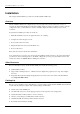
DI-1162/DI-1162M Remote Access Router Installation This chapter details installation procedures for the DI-1162/DI-1162M router. Overview The DI-1162/DI-1162M can be configured in two ways; through a direct serial connection (a console), or remotely, through the included Router Configuration Utility, Telnet, etc. Please note that if you wish to remotely configure the router, you must still use a console to initially configure the LAN or WAN port for a remote connection.
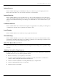
DI-1162/DI-1162M Remote Access Router ♦ Rack mount kit including six screws and two mounting brackets. ♦ One CD-ROM disc or floppy diskette containing the Windows-based Router Configuration Utility. ♦ This User’s Guide. If any item is found missing or damaged, please contact your local D-Link Reseller for replacement. Identifying External Components The following section illustrates the different components on the router’s front and rear panels.
DI-1162/DI-1162M Remote Access Router LED STATUS/ FUNCTION Power Lights whenever the router is plugged in, turned on, and thus receiving power. Diag Lights during the startup Power-On Self-Test (POST) test. Boot Lights briefly during startup after the PROM program has executed. Indicates a successful boot up. Run Should be slowly blinking if the router is functioning properly. 10/100 This LED is ON for a 100Mbps link, and OFF for a 10Mbps link.
DI-1162/DI-1162M Remote Access Router to another 10/100M auto-negotiation capable port, the two ports will configure themselves to attain the best connection possible. ♦ Fan Provides ventilation inside the router. Please ensure to leave adequate space at the rear and sides of the unit for proper ventilation. ♦ Power Socket A standard 100~240V socket for the power cord. ♦ Power Switch A rocker switch that turns the router off and on.
DI-1162/DI-1162M Remote Access Router Step 1 - Setting up the Console The initial setup of the DI-1162/DI-1162M requires connecting a console to the 9-pin RS-232 Diagnostic port on the router’s front panel. A serial cable is supplied with the router in order to make this connection. A console can be a terminal, such as a VT-100, or a normal PC running terminal emulation software (such as Microsoft HyperTerminal, included with Windows).
DI-1162/DI-1162M Remote Access Router To log on to the router, use the factory set username and password ‘Admin’ (without the quotes). Please note that the user name and password are case-sensitive. Upon entering the username and password (using the key to jump to the next field), position the cursor on OK and press .
DI-1162/DI-1162M Remote Access Router Step 3a - Configuring the LAN Port Preparing the router for connection to a LAN only requires enabling the LAN port, enabling IP networking ,and assigning the LAN port an IP address. After the LAN port is configured, all other features on the router can be configured remotely through the LAN by using the included Windows-based Router Configuration Utility or Telnet. To configure the LAN: 1. The LAN port must be enabled in the Interface Configuration submenu.
DI-1162/DI-1162M Remote Access Router Each WAN port can be configured to either receive dial-in calls (act as a Remote Access Server), dial out to other routers (at branch offices or the Internet, for instance), or both (but not at the same time). The WAN ports can also be configured for a leased line (synchronous) connection. Please note however that we recommend only one single WAN connection to the Internet since a second connection will not significantly enhance the performance of the connection.
DI-1162/DI-1162M Remote Access Router ♦ Other items in this screen may also need to be configured such as the State, Routing and Multicast settings. Please refer to the appropriate section in the “Configuration and Management” chapter of this manual for detailed explanations concerning the nature and use of these items. ♦ Position the cursor on the Save option at the bottom of the screen and press to save the new setting. ♦ Choose Exit in the submenus to return to the Main Menu.
DI-1162/DI-1162M Remote Access Router ♦ Change the State to Enable. ♦ Please refer to the “Configuration and Management” chapter of this manual for more detailed information regarding the items in this screen. ♦ Position the cursor on the Save option at the bottom of the screen and press to save the new setting. ♦ Choose Exit in the submenus to return to the Main Menu. 7. Define a WAN port for a leased line connection.
DI-1162/DI-1162M Remote Access Router Step 7 - Powering Up the DI-1162/DI-1162M After all the devices are powered up, the DI-1162/DI-1162M can be turned ON. The router will perform a POST (Power-On Self-Test). It is during this POST procedure that the PROM Configuration Menu can be accessed. The router is now able to use the LAN and WAN ports. The router must be further configured for managing your network.
DI-1162/DI-1162M Remote Access Router Configuration and Management After the initial startup (POST) test, the router will prompt you for login and password. This is the opening page of the router’s configuration program, called the Console program. The Console program is stored in the Flash memory chips in the router and the settings are written in EEPROM chips in the router. It is the most basic level for configuring and managing the router and the network to which it is connected.
DI-1162/DI-1162M Remote Access Router As mentioned earlier, your first endeavor should be to increase the automatic timeout. Enter the System Information to do this.
DI-1162/DI-1162M Remote Access Router ♦ System Description – This is a non-changeable, short description of the product. ♦ System Object ID – This is the enterprise-specific MIB Object ID indicating this type of router. ♦ System Up Time – Shows how long the router has been running since the last power off or reset. ♦ System Contact – Enter the name of the department or individual responsible for maintaining the router. ♦ System Name – Give the router a descriptive name for identification purposes.
DI-1162/DI-1162M Remote Access Router LAN The parameters are described below: ♦ Description – This is a user-defined, 32-character identifier used to name the LAN. ♦ Operation Mode – The LAN port is automatically set to auto-negotiation. When connected to another LAN port, 10/100 Fast Ethernet will configure this port to match the settings of the other LAN port. If the other port also implements 10/100 Fast Ethernet, the two ports will auto-negotiate the best possible settings achievable by both ports.
DI-1162/DI-1162M Remote Access Router WAN The parameters are described below: ♦ Description – This is a user-defined, 32-character identifier used to name the WAN. ♦ Modem Init String – This parameter is valid only for asynchronous connections. It is a user input AT command string to initialize a modem or ISDN TA attached to the WAN interface. Please refer to your WAN device’s handbook for more information about using initialization command strings.
DI-1162/DI-1162M Remote Access Router 4. PPP_ASYN – This serial line encapsulation provides a method for transmitting datagrams over asynchronous serial point-to-point links. Unlike the SLIP protocol, PPP can determine the IP address configuration automatically. 5. FRAME_RELAY – This serial line encapsulation provides a method for high speed transmission of datagrams over dedicated lines. We currently only support PVC.
DI-1162/DI-1162M Remote Access Router WAN Frame Relay Config This screen allows you to specify which WAN 1 or WAN 2 Frame Relay is to be configured by highlighting the desired entry below and then hitting . Next, enter a Data Link Connection Identifier (DLCI) between 16 and 991 and Enable it in the State field on the following screen. Additionally, you must choose the appropriate Switch Type on the WAN Frame Relay Config screen below to complete the WAN Frame Relay configuration.
DI-1162/DI-1162M Remote Access Router The parameters are described below: ♦ DLCI(16. .991) – This Data Link Connection Identifier is used to match your Frame Relay subscription.. ♦ State – This is a toggle, to Disable or Enable the WAN interface.
DI-1162/DI-1162M Remote Access Router IP Configuration IP networking and router advertisement are enabled on the IP Configuration screen: The parameters are described below: ♦ IP Networking – The IP Networking function can toggle to connect/disconnect this router from the entire IP network. When IP Networking is disabled, all routing functions are stopped. The only IP Address the router will act on is it’s own, via Telnet for example.
DI-1162/DI-1162M Remote Access Router Below, the submenus for both the LAN and WAN interfaces are shown.
DI-1162/DI-1162M Remote Access Router The parameters are described below: ♦ IP Address – This is the IP address for the router on the network to which this interface is connected. ♦ Netmask – This is a 32-bit bit mask that shows how the IP address is to be divided into network, subnet and host parts. The netmask has ones in the bit positions in the 32-bit address which are to be used for the network and subnet parts, and zeros for the host part.
DI-1162/DI-1162M Remote Access Router 3. Talk – The router will send adjacent routers it’s own routing table, but will not incorporate routing information from them. 4. Both – The router will incorporate routing information from adjacent routers, and will send adjacent routers it’s own routing table. ♦ IP Multicasting – This feature enables or disables the router’s ability to perform IP multicasting. When enabled, the router will perform IGMP. It can also perform DVMRP if this feature is enabled below.
DI-1162/DI-1162M Remote Access Router The descriptions for all the fields are the same as in the previous section. IP Static Route A static route is a permanent entry in the routing table. Static routing provides a means of explicitly defining the next hop router for a particular destination network IP address. Each static route entry also allows for a metric (a.k.a. hop count) to be specified.
DI-1162/DI-1162M Remote Access Router ♦ IP Address – This specifies the destination network IP address (or a host, depending on the netmask) and pairs it with a gateway. ♦ Netmask – This mask shows how the destination IP address is to be divided into network, subnet and host parts. The netmask has ones in the bit positions in the 32-bit address which are to be used for the network and subnet parts, and zeros for the host part.
DI-1162/DI-1162M Remote Access Router The parameters are described below: ♦ OSPF Router ID – This is a 32-bit number that uniquely identifies the router in the Autonomous System. If the OSPF Router ID is not configured, the router will automatically choose LAN 1’s IP as the OSPF Router ID. ♦ AS Border Router – Setting to allow DI-1162/DI-1162M to act as Autonomous System Border Router. As an AS Border Router, the router can import and export routing information of other Autonomous Systems, such as RIP.
DI-1162/DI-1162M Remote Access Router Complete the OSPF configuration information on the screen below: The parameters are described below: ♦ Area ID – Enter the OSPF Area ID number in this field. ♦ Authentication Type – Toggle between None and SimplePasswd.
DI-1162/DI-1162M Remote Access Router ♦ Stub Area – Toggle between Yes and No. AS external advertisements are not flooded into/throughout stub areas. Routing to AS external destinations in these areas is based on (per area) default only. ♦ Stub Default Cost (0. . 255) – Enter a Stub Default Cost between 0 and 255 in this field. ♦ State – This enables or disables a particular entry.
DI-1162/DI-1162M Remote Access Router The parameters are described below: ♦ Area ID – Enter the OSPF Area ID number in this field. ♦ Output Cost (0 . . 65535) – The cost of sending a packet on the interface, expressed in the link static metric. This is advertised as the link cost for this interface in the router’s router links.advertisement. The interface Output Cost(s) must always be greater than 0. ♦ Router Priority (0. .
DI-1162/DI-1162M Remote Access Router Complete the OSPF virtual interface configuration information on the screen below: The parameters are described below: ♦ Transit Area ID – Enter the Transit Area ID number in this field. ♦ Neighbor Router ID – Enter the Neighbor Router ID number in this field.
DI-1162/DI-1162M Remote Access Router ♦ Hello Interval (1. . 65535) – The length of time (in seconds) between the Hello Packets that the router sends on the interface. This value is advertised in the router’s Hello Packets. It must be the same for all routers attached to a common network. The smaller the Hello Interval, the faster topological changes will be detected, but more OSPF routing protocol traffic will ensue. ♦ Dead Interval (1. .
DI-1162/DI-1162M Remote Access Router Bridge Settings The parameters are described below: ♦ Bridge ID – The Bridge ID is a read-only object composed of the bridge priority and the MAC address. So in the screen above, the Priority is 32768 and the MAC address is zero since it was yet to be entered. ♦ Priority – A Bridge Priority is a read-write object that can be set from 0 to 65535. This is the priority number of the bridge.
DI-1162/DI-1162M Remote Access Router ♦ Priority – Port Priority is a read-write object that can be set from 0 to 255. The priority is used to determine the designated port if the Path costs of redundant switch to switch connections are the same. The higher the port priority, the more chance the port has of becoming the designated port. Zero is the highest priority.
DI-1162/DI-1162M Remote Access Router The parameters you can set is described below: ♦ IPX Networking – The IPX Networking function is enabled or disabled in this field. Enable it to set up IPX (Internetwork Packet eXchange), a routing protocol for Novell networking environments. IPX Stack Configuration This menu is used to configure the LAN and WAN interfaces.
DI-1162/DI-1162M Remote Access Router Complete the IPX stack configuration information for the desired interface on the screen below: The parameters described below also apply to WAN interfaces.: ♦ IPX Network Number – This determines which IPX network you belong to. ♦ Frame type – Select from the following: Ether II, SNAP, 802.2, or 802.3 ♦ IPX RIP – Enable IPX Routing Information Protocols (RIP) to provide a measure of distance, or hops, from a transmitting system to a receiving system.
DI-1162/DI-1162M Remote Access Router IPX Static Route The parameters are described below: ♦ Network – This is the IPX network number. ♦ Next Node Address – This is the next node address of the device that the router will attempt to reach. ♦ Hops – This counts how many routers were passed through before the packet’s final destination on a network was reached. The number of hops is part of each network entry in a RIP packet. ♦ Ticks – This is the time delay to reach a network.
DI-1162/DI-1162M Remote Access Router SPX Static Service Select an entry and then press . The parameters are described below: ♦ Service Name – This is the name that has been configured for the server. This name must be the exact name configured in the NetWare server.
DI-1162/DI-1162M Remote Access Router ♦ Type – This field identifies the type of service the server provides. ♦ Network Number – This is the SPX network number. ♦ Node Address – This field contains the address of the node on which the server resides. ♦ Socket – This field contains the socket number on which the server will receive service requests. ♦ Hops – This counts how many routers were passed through before the packet’s final destination on a network was reached.
DI-1162/DI-1162M Remote Access Router SNMP Community Configuration Select and enter the SNMP Community Configuration submenu. You will see the following configuration screen: The parameters are described below: ♦ SNMP Community String – This community string is a user-defined identifying name used to group together some arbitrary set of SNMP application entities managed by the network manager. ♦ Access Right – This element of the set (Read Only, Read/Write) is called the SNMP access mode.
DI-1162/DI-1162M Remote Access Router The parameters are described below: ♦ IP Address – Enter the IP address of the host who will act as an SNMP Management Station. The DI-1162/DI1162M router will send SNMP traps to these addresses. ♦ SNMP Community String – The community string is a user-defined identifying name used to group together some arbitrary set of SNMP application entities managed by the network manager.
DI-1162/DI-1162M Remote Access Router Remote Access Configuration The Remote Access Configuration menu is used to set up the router for dial-in and dial-out connections through modems and/or ISDN devices attached to the WAN ports.
DI-1162/DI-1162M Remote Access Router 6. In the case where the Dial-In User does not need to supply a Username and Password (Auth Type is set to None in the Interface Configuration submenu) the remote computer must have its own IP address. Remote Network Connections Remote networks are defined as other networks (LANs) that have WAN connections using a router, Internet server, network modem or similar device (in this document however, we will assume the remote device is a router).
DI-1162/DI-1162M Remote Access Router Dial Configuration You can configure the two WAN interfaces on your DI-1162/DI-1162M to dial-out only when a packet is forwarded to that interface, and hang up after all data has been transferred and the link is idle. This can be used to lower the cost of an unpopular link or used as a backup link to your ISP. This feature is commonly called “Dial on Demand”.
DI-1162/DI-1162M Remote Access Router Dial In IP Pool The dial in IP pool allows you to define a range of IP addresses that will be reserved for and assigned to dialin users. The items are described as follows: ♦ IP Address – This is the first IP Address that will be assigned to a dial-in user. ♦ Range – This is the number of IP Addresses that can be assigned. In the window shown above, dial-in users will be assigned the IP Addresses 170.100.200.1 or 170.100.200.
DI-1162/DI-1162M Remote Access Router The items are described as follows: ♦ Backup State – Choose among Answer, Dial on Demand, Always Connect, or Disable. ◊ Answer Select this to accept phone calls. ◊ Dial on Demand This initiates phone calls to make a connection. ◊ Always Connect When this is selected, the primary line will never have a chance to be activated again. ◊ Disable Select this if you don’t want the backup function to be used.
DI-1162/DI-1162M Remote Access Router The parameters are described below: ♦ Dial Retry Time – This is the time (in seconds) the router will wait before the next dial attempt. ♦ Dial Retry Count – This is the specified maximum number of dial attempts the router will make when trying to establish a connection on this interface. ♦ Call Back Delay – This is the time (in seconds) the router will wait before calling the number designated for a specified dial-in user.
DI-1162/DI-1162M Remote Access Router Select an entry from above and hit . This screen will be blank if a dial-in user profile has not been configured yet. The parameters in the above window are described as follows: ♦ Name – The maximum length is 64 characters. This username is for password challenges (authentication). The user dialing in must supply this username in order to be allowed access to the router. ♦ Password – This is the password associated with the above Name field.
DI-1162/DI-1162M Remote Access Router ♦ Rem CLID – Remote Caller ID. This is the telephone number of the Remote User and is used for security. When a phone number is entered in this field, the router will make sure that the incoming call is coming from the same phone number as the one defined here. In other words, the remote user can only be calling from the telephone number defined here, otherwise the call will not be accepted. This function is disabled if the field is left blank.
DI-1162/DI-1162M Remote Access Router Select an entry from above and hit . This screen will be blank if a remote network profile has not been configured yet. The parameters in the above window are described as follows: ♦ Remote Name – Name for the remote network that the DI-1162/DI-1162M is being set up to connect with. ♦ Direction – Dial-[In], dial-[Out], or [Both].
DI-1162/DI-1162M Remote Access Router ♦ Set Peer as default Gateway – When enabled, this feature sets the IP address of the remote device as the default gateway (default next hop router) for all packets not found in the routing table.
DI-1162/DI-1162M Remote Access Router Script File Configuration Script files are used on dial-out connections where the server you are connecting to uses a script for the logon procedure (common with many ISP’s). If you would like the router to automatically logon to a remote server, you must define a script file. Script files are executed immediately upon successfully establishing a connection. The DI-1162/DI-1162M can hold up to 8 different script files.
DI-1162/DI-1162M Remote Access Router Commands Script files can perform six Commands. You can choose the appropriate command by positioning the cursor in the Command field and pressing to toggle to the desired command. The script commands are defined as follows: ♦ Wait – This command waits for text defined in the Parameter field to be transmitted by the ISP. In the above example, the router will wait for the ISP to prompt for ‘Username:’.
DI-1162/DI-1162M Remote Access Router DHCP Configuration The DI-1162/DI-1162M Router implements the Dynamic Host Configuration Protocol (DHCP), which allows the entire IP network to be centrally managed by the router. It does this by assigning IP addresses and configuration parameters to hosts as they are powered on and come onto the network. This can be a great help for network administration since many administrative tasks such as keeping track of each computer’s IP address are handled by the router.
DI-1162/DI-1162M Remote Access Router Dynamic IP Pool The Dynamic IP Pool screen shown below contains the parameters that the router can set on the hosts. Please note that the Dynamic IP Pool cannot be enabled when the DHCP Agent feature is enabled. The parameters are described below: ♦ IP Address – This is the base (starting) address for the IP pool of unassigned IP addresses.
DI-1162/DI-1162M Remote Access Router ♦ Range – This is the range of contiguous, IP addresses, above the base IP Address above. In the above example, the IP Addresses assigned would be 202.93.47.1, 202.93.47.2, … 202.93.47.100. ♦ Netmask – This mask informs the client, how the destination IP address is to be divided into network, subnet, and host parts. The netmask has ones in the bit positions in the 32-bit address which are to be used for the network and subnet parts, and zeros for the host part.
DI-1162/DI-1162M Remote Access Router The parameters are described below: ♦ IP Address – This is the static IP address to be assigned. ♦ MAC Address – This specifies the physical address of the particular host that will receive the above IP address. All other parameters (Netmask, Gateway, DNS IP, WINS IP, State, and Domain Name) are identical to those in the Dynamic IP Pool configuration, in the previous section.
DI-1162/DI-1162M Remote Access Router Items are described as follows: ♦ DHCP Server IP Address – This is the IP address of the remote DHCP server. When a local computer powers up and sends a DHCP request for an IP address, the DI-1162/DI-1162M will forward the request to the address specified here. ♦ Time Threshold – This specifies the maximum amount of time (in seconds) since the host began requesting an IP address.
DI-1162/DI-1162M Remote Access Router The three submenus are described as follows: 1. Filter State of Interface – This is used to choose the default, routing decisions for packets, not meeting the criteria for specific filters. 2. Layer 2 Filter – This is a data-link layer (protocol independent) filter. Foreknowledge of the specific protocol, used on the interface (LAN or WANs), is needed to make effective use of this filter. 3.
DI-1162/DI-1162M Remote Access Router Please note that the IPX Filter column will only appear on DI-1162M models. Each decision on handling packets is described below: 1. Disable – This does not apply a default, routing decision. 2. Forward – This allows the routing of a packet, even though it has not met the criteria of the corresponding filter. 3. Drop – This drops (doesn’t allow routing for) a packet that has not met the criteria for the corresponding filter.
DI-1162/DI-1162M Remote Access Router Select an entry from above and hit . This screen will be blank if a layer 2 filter has not been configured yet. The parameters of a filter are described below: ♦ Name – This is a 12 character (maximum), alphanumeric, user-defined name, used to identify the filter. ♦ Direction – This defines the direction of the frame relative to the Interface parameter. In means that packets will be checked when they are received from this interface.
DI-1162/DI-1162M Remote Access Router ♦ State – This is used to choose the routing decision applied to the frame. The three decisions are described: 1. 2. 3. Forward – This allows the routing of the frame, if it has met the criteria of the corresponding filter. Drop – This drops (doesn’t allow routing for) a specific frame that has met the criteria of the corresponding filter. Disable – This does not apply the protocol independent filter.
DI-1162/DI-1162M Remote Access Router The IP Filter parameters are described below: ♦ Name – This is a 12 character (maximum), alphanumeric, user-defined name, used to identify the IP filter. ♦ Direction – This defines the direction of the packet relative to the Interface parameter below. ♦ State – This is used to define the routing decision applied to the packet. The three routing decisions are described: 1. 2. 3.
DI-1162/DI-1162M Remote Access Router ♦ Dst Netmask – This mask is bit-wise AND’d with the destination IP address, and compared to the IP address of the outgoing interfaces. ♦ Dst Port – This is the destination port, in the TCP or UDP header, of the packet. ♦ Dst Port Operation – This comparison operation is applied to the destination port (the Dst Port parameter) value, of the TCP or UDP header. ♦ ICMP Type – This is the type field, in the ICMP header, used to identify a particular ICMP message.
DI-1162/DI-1162M Remote Access Router Select an entry from above and hit . This screen will be blank if an IPX filter has not been configured yet. The IPX Filter parameters are described below: ♦ Name – This is a 12 character (maximum), alphanumeric, user-defined name, used to identify the IPX filter. ♦ State – This is used to define the routing decision applied to the packet. The three routing decisions are described: 1.
DI-1162/DI-1162M Remote Access Router 2. 3. Drop – This drops (doesn’t allow routing for) a specific packet that has met the criteria of the corresponding IPX filter. Disable – This does not apply the IPX filter. ♦ Direction – This defines the direction of the packet relative to the Interface parameter below. ♦ Interface – This applies the filter to a specific interface, LAN or one of the WANs. ♦ Packet Type – Defined by Novell for special services.
DI-1162/DI-1162M Remote Access Router reserved for LAN1 and MIP4 to MIP6 are reserved for LAN2 (if present). This type of configuration is known as a multiple home configuration. Multiple Home can be demonstrated by this example: A company has 625 users (computers) all connected to one physical network using Ethernet. However, the company only has one Class C IP network address, 202.100.160.0. This network address will only support 254 users.
DI-1162/DI-1162M Remote Access Router The parameters are described below: ♦ IP Address – This is a network IP address, access point, to a separate, physical network, on the LAN. ♦ Routing Protocol – This is the same as in the Network Configuration section. Keep in mind that these exchanges are made with adjacent routers on the LAN, if present. ♦ IP Multicasting – This enables/disables IP multicasting on the IP network you are defining.
DI-1162/DI-1162M Remote Access Router Select an entry from above and hit . This screen will be blank if a static ARP entry has not been configured yet. The parameters are described as follows: ♦ IP Address – This is the IP address that causes the router to reply with the MAC Address upon receiving an ARP request. ♦ MAC Address – This is the physical address, of the host, that is the authorized owner of the IP address.
DI-1162/DI-1162M Remote Access Router ♦ State – This toggles Enable and Disable. NAT Configuration Network Address Translation (NAT) is a routing protocol that allows your network to become a private network that is isolated from, yet connected to the Internet. It does this by changing the IP address of packets from a global IP address usable on the Internet to a local IP address usable on your private network (but not on the Internet) and vice-versa. NAT has two major benefits.
DI-1162/DI-1162M Remote Access Router Please note that in the above diagram, the Gateway IP address settings for the local PC’s needs to be set to 192.168.100.1, the LAN IP address of the router. NAT manipulates the IP addresses in packet headers on a one-to-one basis. An outgoing data packet (a packet originating from a computer on the local LAN and destined for a computer outside the private network) will have its IP address translated as shown below.
DI-1162/DI-1162M Remote Access Router When a packet on the local network arrives at the router and needs to be sent to the Internet, NAT will change the source IP address (for example 192.169.100.2) to a global address (200.100.50.1, for example). If this packet generates a reply (as for example, a request to view a web page will), NAT will change the destination IP address on the reply packet back to the local IP address for delivery to the machine on the local (stub) network.
DI-1162/DI-1162M Remote Access Router Configure NAT/NAPT The first screen shows the complete NAT table that is defined by the network manager: For any NAT entry, you must configure two different screens. The first one is accessible by positioning the cursor over the name field and hitting (in the window shown above, this corresponds to the field ‘02507’).
DI-1162/DI-1162M Remote Access Router The parameters are described as follows: ♦ Name – This is a 12 character, alphanumeric, user-defined name, used to identify the network address translation. ♦ Global Interface – This is the interface corresponding to the Global IP and Range parameters, in the NAT table, to form unique IP address[es], known to the outside (regional or Internet) routers, on this interface.
DI-1162/DI-1162M Remote Access Router NAT IP Pool Configuration Screen Now you must select, enter, and configure the NAT IP Pool from the NAT Configuration submenu, shown below. Dynamic NAT This screen (below) is how the NAT IP Pool appears, if Dynamic NAT was chosen for the Translation Mode parameter. Each entry, in this configuration, can be used to map multiple, contiguous global addresses and local addresses to each other.
DI-1162/DI-1162M Remote Access Router All of the parameters are the same as in Dynamic NAT, except the Global IP is a solitary, global address. ♦ Global IP – this is a single, globally unique IP Address of the global interface (the interface to which it is assigned, in this case, one of the WAN interfaces) that is valid on the Internet. Static NAT This screen (below) is how the NAT IP Pool appears, if Static NAT was chosen for the Translation Mode parameter.
DI-1162/DI-1162M Remote Access Router The parameters are described as follows: ♦ Global IP – This is a single, global IP Address that is valid on the Internet, or on the same subnet of the global interface. ♦ Local IP – This is a single, local IP Address that is not valid on the Internet. Static NAPT This screen (below) is how the NAT IP Pool appears, if Static NAPT was chosen for the Translation Mode parameter.
DI-1162/DI-1162M Remote Access Router In the above window, position the cursor on any of the numbered name fields and press . This will take you to the NAPT configuration screen for special applications shown below. The fields in the above window are described as follows: ♦ Protocol – UDP or TCP. This field designates the type of packets that will be acted on.
DI-1162/DI-1162M Remote Access Router ♦ Start Port – Some applications can only send data over a certain range of port numbers. Thus, all port numbers in the specified range must be exempt from the NAPT port translation process. This field defines the beginning range of the port numbers to be exempted from the NAPT port translation process. ♦ End Port – This field defines the last port number in the range of numbers excluded from the NAPT process (see Start Port above).
DI-1162/DI-1162M Remote Access Router DNS Configuration The DI-1162/DI-1162M router has a built in recursive DNS server. The maximum amount of memory that will be used by the router’s Domain Name Server is 64Kb which averages out to be about 800 entries. In other words, up to 800 domain names and their associated IP Addresses can be stored, which can significantly speed up access to those domains.
DI-1162/DI-1162M Remote Access Router Host Table The host table allows the router to recognize host names on the network. Up to eight host names can be entered in the table. Your network servers, especially your mail server should be defined here. Leftover places in the table can be assigned to individual hosts to speed up routing. In the example below, the host name ctsnow is combined with the domain name defined in the DNS Configuration submenu above (in this case, dlink.com) to produce ctsnow.dlink.com.
DI-1162/DI-1162M Remote Access Router Items in the above submenu are described as follows: ♦ RADIUS State – Enables or disables RADIUS. ♦ Type – Refers to the type of external password protocol. Currently, only RADIUS is supported. ♦ Server IP Address – This is the IP Address of your UNIX or NT-based RADIUS server. ♦ Port – The port number for the RADIUS server. The standard port number specified by RFC 1700 is 1812 (shown above).
DI-1162/DI-1162M Remote Access Router A static implementation of MLPPP is achieved when BOD is disabled but the WAN ports have Multi-Link enabled. In this case, when the two WAN ports have established a connection, the router will check to see if they are connected to the same source and whether the source supports MLPPP. If both conditions are met, the router will automatically bundle the two links together as an MLPPP connection.
DI-1162/DI-1162M Remote Access Router The example Multi-link PPP settings shown in the Multi-Link PPP Configuration window above assumes that WAN 1 and WAN 2 each have a 64 kps connection configured to dial up to the Internet. When WAN 1 receives a packet destined for the Internet it will dial the ISP and establish a connection. If the total throughput on WAN 1 (TX or RX) ever exceeds 80% of the 64 kps (51.2 kps), the router will sample the line for an additional 5 seconds.
DI-1162/DI-1162M Remote Access Router System Status The System Status submenu displays key information about the router and appears as follows: Counter Under the Statistics item of the System Maintenance screen is a Counter menu that displays some of the counters contained in MIB-II and the proprietary MIB.
DI-1162/DI-1162M Remote Access Router a system reset on the router. Note that performing a system reset clears ALL tables in the router, including the routing table. Select the desired entry from the screen below and then press . LAN 1 Items in the screen are described as follows: ♦ Tx Packets – The total number of valid packets transmitted by the router since the last reset.
DI-1162/DI-1162M Remote Access Router ♦ Tx Bytes – The total number of bytes transmitted by the router. ♦ Tx Discard Packets – The number of packets dropped by the router. ♦ Tx Error Packets – The number of invalid packets transmitted by the router. This hardware counter shows the sum of Collisions, Abort, and Underrun packets. ♦ Tx Collision Packets – The number of packets sent out of the router that collided on the line. Some collisions are inevitable due to the shared nature of Ethernet.
DI-1162/DI-1162M Remote Access Router WAN 1 Items in the screen are described as follows: ♦ Tx Packets – The total number of valid packets transmitted by the router since the last reset. ♦ Tx Bytes – The total number of bytes transmitted by the router. ♦ Tx Discard Packets – The number of packets dropped by the router. ♦ Tx Error Packets – the number of invalid packets transmitted by the router. This hardware counter shows the sum of Collisions, Abort, and Underrun packets.
DI-1162/DI-1162M Remote Access Router ♦ Rx Overrun Packets – The number of packets received that exceed the 1518 octet maximum length imposed on Ethernet packets. Overrun packets are generated by some proprietary software applications. ♦ Rx CD Lost Packets – Carrier Detect Lost. This counts the number of Carrier Detect packets that were lost by the router. ♦ Rx Framing Err Packets – Packets with framing errors can occur on the WAN port only when using HDLC in sync mode.
DI-1162/DI-1162M Remote Access Router Items in the screen are described as follows: ♦ IP Address – This is the destination, network IP address from an incoming packet. ♦ Netmask – This mask is received from RIP exchanges and internal calculations, as the router learns. ♦ Gateway – This is the next-hop router for which the packet, with destination IP Address and qualifying Netmask, will be forwarded. ♦ If – This is the outgoing interface for which the acceptable, routing packet will be forwarded.
DI-1162/DI-1162M Remote Access Router IPX Routing Table This table displays IPX topology information (DI-1162M only). Items in the screen are described as follows: ♦ Net No – This displays the selected network number. ♦ Next Node Address – This is the node address that will be used next. ♦ Interface – This is the interface of this item. ♦ Hop – This is the hop count.
DI-1162/DI-1162M Remote Access Router SAP Table This table displays Service Advertising Protocol information (DI-1162M only). Items in the screen are described as follows: ♦ Name Network – This displays the selected name network. ♦ Type – This displays the type of service based on numbers and services defined by Novell. ♦ Net No –This displays the network number. ♦ Node Addr – This displays the node address. ♦ Socket – This displays the socket number. ♦ Hops –This displays the hop count.
DI-1162/DI-1162M Remote Access Router Select an interface from the screen above and press to view the current PPP status: Items in the screen are described as follows: ♦ Interface – This displays the selected interface. ♦ BACP – Bandwidth Access Control Protocol is used to control bandwidth between routers. ♦ CCP – Compress Communication Protocol is used to compress data sent between routers. ♦ IPNCP – IP Network Control Protocol is used to keep lines open between IPs.
DI-1162/DI-1162M Remote Access Router Log and Trace This feature file events and errors that occurred and allows individual packets to be captured in a buffer. These items are to help D-Link technical support personnel identify problems that may be affecting your router. If problems occur with your router, D-Link technical support personnel will guide you through the use of these features.
DI-1162/DI-1162M Remote Access Router Event/Error Log Log Configuration This option allows you to Enable or Disable the Event/Error log and begin recording events.
DI-1162/DI-1162M Remote Access Router View Log File This displays the Event/Error Log file shown below: The following parameters help technical support personnel evaluate events: ♦ Code – A special code for categorizing events. ♦ Port – The interface on which an event occurs. ♦ Time – Tick-times denoting when events occurred. ♦ Data – Data petaining to specific events. Trace Buffer This feature captures packets in a buffer to help D-Link technical support personnel identify problems with your router.
DI-1162/DI-1162M Remote Access Router Trace Buffer Configuration Enables or disables the Trace buffer feature. View Trace Buffer Displays the header of packets captured in the buffer.
DI-1162/DI-1162M Remote Access Router The contents are described as follows: ♦ Port – This is the interface from which the packets were captured. ♦ Time – In clock ticks. The time the packet was captured. ♦ Data – The contents of the header of the packet. Packet Triggered Last Call This function enables you to determine what type of packet triggered the last call. This is useful when a network administrator wants to control access and costs.
DI-1162/DI-1162M Remote Access Router Diagnostic This feature tests the connection between the router and connected peripherals on a given interface. Please note that the IPX Ping Test is for the DI-1162M only. Connection Test This feature tests a dial-out WAN connection.
DI-1162/DI-1162M Remote Access Router The parameters are described as follows: ♦ Interface – The WAN interface to be tested. ♦ Phone Number – The phone number that will be dialed by the WAN Interface. Please ensure that a modem answers the phone on the other end. ♦ Baud Rate – The rate of data transmission. The answering modem must be capable of operating at the baud rate defined here. ♦ Connection Test – Press to begin the test.
DI-1162/DI-1162M Remote Access Router The parameters are described as follows: ♦ IP Address – This is the IP Address of the device that the router will attempt to reach. The router will check it routing table and try to locate the IP Address. ♦ Count – The number of pings (packets) that will be sent. ♦ Delay (10ms) – The amount of time in 10 millisecond intervals between each ping in the Count. ♦ Start Ping Test - Press or to begin the test.
DI-1162/DI-1162M Remote Access Router The parameters are described as follows: ♦ IPX Net – This is the IPX network number. ♦ Node Address – This is the node address of the device that the router will attempt to reach. The router will check its routing table and try to locate the IPX Address. ♦ Count – The number of pings (packets) that will be sent. ♦ Delay (1 sec) – The amount of time in 1 second intervals between each ping in the Count. ♦ Start Ping Test - Press or to begin the test.
DI-1162/DI-1162M Remote Access Router System WAN The System WAN test is used to diagnose the WAN port. It can only be run if the WAN port is disabled in the Interface Configuration submenu. Software Update Menu New routing software can be downloaded from a TFTP server. If you do not have a TFTP server on your LAN, you can use the included Router Configuration Utility to upgrade the software.
DI-1162/DI-1162M Remote Access Router This is the same Software Update Menu as in the “PROM System Configuration” chapter’s Software Update Menu. The parameters are described in that section. Perform a System Restart after configuring these settings begins the software update procedure. System Restart The system restart function enables you to reset the DI-1162/DI-1162M without powering off. Some settings changes require a system restart in order for them to take effect.
DI-1162/DI-1162M Remote Access Router Factory Reset Performing a factory reset erases all settings and tables. All configuration changes ever made to the router will be deleted. The router will be set to the factory defaults it was shipped with and will no longer have an IP address. Please make sure you wish to wipe out all settings and configure the router from scratch before you perform a factory reset.
DI-1162/DI-1162M Remote Access Router System Settings Backup/Restore The backup and restore system settings functions are used to backup the router settings. The files created by this process is different than a configuration file or the software update file that are used in the Software Update Menu.
DI-1162/DI-1162M Remote Access Router Backup System Settings Items in the window are described below: ♦ Remote IP Address – This is the IP address of the TFTP server on which you wish to store the settings file. ♦ TFTP Time Interval – The time between requests to occupy TFTP server time. If the router doesn’t receive a response (ACK) from the TFTP server within the time interval defined here, it will assume the request has been dropped and send another.
DI-1162/DI-1162M Remote Access Router Backup System Settings Items in the window are described below: ♦ Remote IP Address – This is the IP address of the TFTP server on which you wish to store the settings file. ♦ TFTP Time Interval – The time between requests to occupy TFTP server time. If the router doesn’t receive a response (ACK) from the TFTP server within the time interval defined here, it will assume the request has been dropped and send another.
DI-1162/DI-1162M Remote Access Router PROM System Configuration The PROM program is run before the normal console (runtime) configuration program in the router’s Flash Memory. Thus, the PROM System Configuration can be used if there are problems with the router’s console program.
DI-1162/DI-1162M Remote Access Router System Configuration Menu The parameters are described as follows: ♦ Hardware Revision – This is the version ID of hardware used in this router. ♦ Boot PROM Firmware Version – This is the version ID of firmware used in this router. ♦ MAC Address – This is the physical address for this router.
DI-1162/DI-1162M Remote Access Router TCP/IP Parameters Configuration Menu The parameters are described as follows: ♦ Interface – The LAN interface must use Ethernet/Fast Ethernet and is displayed here. This setting cannot be adjusted. ♦ IP Address – This is the router’s IP Address for the LAN interface. ♦ Subnet Mask – This mask shows how the LAN is to be divided into network, subnet, and host parts. ♦ Default Gateway – This is the default gateway for the LAN.
DI-1162/DI-1162M Remote Access Router Software Update Menu The Software Update option is used to change the software in the flash memory of the router. This is the runtime software that is used to configure the router and is described in full in the preceding chapter. The runtime software should only be updated if you are encountering problems with your current runtime software or you are certain your runtime software is lacking functionality contained in a more recent version.
DI-1162/DI-1162M Remote Access Router Items listed in the above menu are described as follows: ♦ Software Update Control – This toggles Disable and Enable. ♦ Software Update Mode – This specifies downloading the image file from a Network server on the local LAN. ♦ Boot Protocol – This setting is for a local network download and has two options TFTP ONLY and BOOTP&TFTP. ◊ TFTP ONLY – A File Transfer Protocol. Using this setting assumes all other items on this screen have been filled out.
DI-1162/DI-1162M Remote Access Router After the new runtime software has been downloaded, the router will automatically start up using the new software with the Software Update Control setting disabled to avoid a downloading loop. Factory Reset Performing a factory reset erases all settings and tables. All configuration changes ever made to the router will be deleted. The router will be set to the factory defaults it was shipped with and will no longer have an IP address.
DI-1162/DI-1162M Remote Access Router Using Telnet The DI-1162/DI-1162M router can be configured and managed using telnet. Telnet accesses the same built-in configuration program as the RS-232 Diagnostic port console connection. As such, all settings that can be adjusted through the console can also be configured using Telnet. Telnet Configuration In order to use telnet, the DI-1162/DI-1162M router must first be configured using a console connected to the RS232 Diagnostic port.
DI-1162/DI-1162M Remote Access Router Installing a RADIUS Server To use RADIUS authentication, you will need to have a UNIX or Windows NT-based machine on your network to act as a RADIUSd server, as well as a copy of the RADIUSd server program itself. You can obtain a copy of the RADIUS software, along with documentation for the server, at http://www.livingston.com/marketing/products/radius.html or at: ftp://ftp.livingston.
DI-1162/DI-1162M Remote Access Router # Client Name Key #----------------------------192.168.0.1 1234 should be added to the client file. The Client Name field in the file gives the IP address of the DI-1162/DI-1162M, and the Key field should be the same as the Key field in menu 23.2. After a RADIUS server has been configured, the DI-1162/DI-1162M will use it to authenticate all users instead of checking it’s internal Dial-Up User Profile.
DI-1162/DI-1162M Remote Access Router Appendix A – Cables and Connectors RS-232 (EIA-574) for Diagnostic Port Pin 1 2 3 4 5 6 7 8 9 Signal Name Mnemonic Recv. Line Sig. Det. (DCD) 109 Received Data 104 Transmitted Data 103 DTE Ready (DTR) 108 Signal Ground 102 DCE Ready (DSR) 107 Request to Send 105/133 Clear to Send 106 Ring Indicator 125 End Connector: DB-9 Pin Male Cable Length: 1.
DI-1162/DI-1162M Remote Access Router RS-449 Cable for WAN Port DB25 Female Pin Number 1 2 3 4 5 6 7 8 9 10 11 12 13 14 15 16 17 18 19 20 21 22 23 24 25 DB37 Male Pin Number Signal Name Mnemonic Source Protective Ground TXD BA RXD BB RTS CA CTS CB DSR CC Signal Ground AB Rec. Line Signal CF Det. 26 RXD CLK DD 31 Rec. Line Signal CF Det.
DI-1162/DI-1162M Remote Access Router V.35 Cable for WAN Port DB25 Female Pin Number 1 2 3 4 5 6 7 8 9 10 11 12 13 14 15 16 17 18 19 20 21 22 23 24 25 V.35 Male Pin Number Mnemonic Source Protective Ground TXD RXD RTS CTS DSR Signal Ground Rec. Line Signal Det.
DI-1162/DI-1162M Remote Access Router Appendix B – Specifications General Network Protocols: WAN Protocols: Routing Protocols: Management: Memory: Flash Memory System Memory No.
DI-1162/DI-1162M Remote Access Router Appendix C - IP Concepts This appendix describes some basic IP concepts, the TCP/IP addressing scheme and show how to assign IP Addresses. When setting up the router, you must make sure all ports to be utilized on the router have valid IP addresses. Even if you will not use the WAN ports, you should, at the very least, make sure the LAN port is assigned a valid IP address.
DI-1162/DI-1162M Remote Access Router The network portion must start with a value from 1 to 126 or from 128 to 223. Any other value(s) in the network portion may be from 0 to 255, except that in class B the network addresses 128.0.0.0 and 191.255.0.0 are reserved, and in class C the network addresses 192.0.0.0 and 223.255.255.0 are reserved. The value(s) in the host portion of a physical device's IP address can be in the range of 0 through 255 as long as this portion is not all-0 or all-255.
DI-1162/DI-1162M Remote Access Router Appendix D – IP Protocol and Port Numbers Common Internet service protocols and IP port numbers.
DI-1162/DI-1162M Remote Access Router Appendix E – Configuration File The router can be configured when performing a Software Update through a configuration file. The configuration file can hold many settings for the router including IP Addresses for all ports, path to the boot server, and various port settings. The configuration file is very useful if you wish to update your software and keep all or most of your settings the same. The configuration file should be saved with the extension .
DI-1162/DI-1162M Remote Access Router ip-address 10.19.88.1 # subnet mask ip-netmask 255.255.255.
DI-1162/DI-1162M Remote Access Router Index DNS Cache State ................................................... 84 DNS Configuration................................................ 84 DNS Domain Name............................................... 84 DNS IP .................................................................. 60 Domain Name........................................................ 60 Dynamic Host Configuration Protocol .................... 2 Dynamic IP Pool ......................................
DI-1162/DI-1162M Remote Access Router POST ............................................................. 17, 113 Powering Up.......................................................... 15 PPP_ASYN ............................................................ 22 PPP_SYN............................................................... 21 private network...................................................... 74 private networks .................................................... 76 PROM System Configuration.......
DI-1162/DI-1162M Remote Access Router Using Telnet via LAN ...................................... 119 Using Telnet via WAN..................................... 119 Telnet Configuration ........................................... 119 Telnet Enable ........................................................ 83 TFTP ................................................................... 117 TFTP server................................................. 107, 116 Time ....................................................
Offices AUSTRALIA D-LINK AUSTRALASIA Unit 16, 390 Eastern Valley Way Roseville, NSW 2069 Australia TEL: 61-2-9417-7100 FAX: 61-2-9417-1077 TOLL FREE (Australia): 1800 177 100 TOLL FREE (New Zealand): 0800-900900 URL: www.dlink.com.au E-MAIL: support@dlink.com.au & info@dlink.com.au CANADA D-LINK CANADA 2180 Winston Park Drive, Oakville, Ontario, L6H 5W1 Canada TEL: 1-905-829-5033 FAX: 1-905-829-5223 BBS: 1-965-279-8732 TOLL FREE: 1-800-354-6522 URL: www.dlink.ca FTP: ftp.dlinknet.
Registration Card Print, type or use block letters. Your name: Mr./Ms_____________________________________________________________________________ Organization: ________________________________________________ Dept.