CopperHead 3400 User Guide M4012-9900-102 24 July 2014
Notices Copyright & Trademark Notice Copyright © 2010–2014, Grass Valley. All rights reserved. Belden, Belden Sending All The Right Signals, and the Belden logo are trademarks or registered trademarks of Belden Inc. or its affiliated companies in the United States and other jurisdictions. Grass Valley, CopperHead 3400 are trademarks or registered trademarks of Grass Valley. Belden Inc., Grass Valley, and other parties may also have trademark rights in other terms used herein.
Table of Contents 1 Introduction . . . . . . . . . . . . . . . . . . . . . . . . . . . . . . . . . . . . . . . . . . . 1 About the CopperHead 3400 Fiber Optic Transceiver System . . . . . . . . . . . . . . . . . . . . . . . 2 About this User Guide . . . . . . . . . . . . . . . . . . . . . . . . . . . . . . . . . . . . . . . . . . . . . . . . . . . . . . . . . 3 Product Returns . . . . . . . . . . . . . . . . . . . . . . . . . . . . . . . . . . . . . . . . . . . . . . . . . . . . . . . . . . . . . . . . . .
Table of Contents Front Panel Section E – Status/Power Indicators. . . . . . . . . . . . . . . . . . . . . . . . . . . . . . . 28 Base Station Rear Panel . . . . . . . . . . . . . . . . . . . . . . . . . . . . . . . . . . . . . . . . . . . . . . . . . . . . . . .29 Rear Panel Section A - Power & Fiber Connectors (Power Module) . . . . . . . . . . . . . 30 Rear Panel Section A - Internal Power Options . . . . . . . . . . . . . . . . . . . . . . . . . . . . . . . .
CopperHead 3400 User Guide The CopperHead 3400 Camera Unit Digital Display . . . . . . . . . . . . . . . . . . . . . . . . . . . .74 The BASE Rx/DIM accesses the Camera Unit . . . . . . . . . . . . . . . . . . . . . . . . . . . . . . . . . . .75 Best Practices . . . . . . . . . . . . . . . . . . . . . . . . . . . . . . . . . . . . . . . . . . . . . . . . . . . . . . . . . . . . . . . . . . . .77 Shutting Down the System . . . . . . . . . . . . . . . . . . . . . . . . . . . . . . . . . . . . . . . . . . . .
Table of Contents 4
Introduction This chapter provides high-level information about CopperHead 3400 system. About the CopperHead 3400 Fiber Optic Transceiver System . . . . . . . . . . . . . . . . . . . . . . . . . . . 2 Safety Information . . . . . . . . . . . . . . . . . . . . . . . . . . . . . . . . . . . . . . . . . . . . . . . . . . . . . . . . . . . . . . . . . . . .
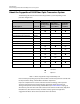
Introduction About the CopperHead 3400 Fiber Optic Transceiver System About the CopperHead 3400 Fiber Optic Transceiver System The following table lists the various items shipped with a system depending on the particular configuration.
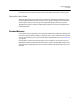
CopperHead 3400 User Guide Leave the protective caps on the optical connectors whenever the fiber is disconnected. About this User Guide This CopperHead 3400 can be delivered in a number of configurations depending on the Power and Battery Mount options selected. This user guide is designed to cover all of the various options and so not every page in this guide will apply to your specific system. Throughout this guide a number of informational pointers are used to mark important or useful information.
Introduction Safety Information Safety Information Optical Fiber Safety To prevent eye damage, never look directly into the end of the optic fiber while either end of the system is operating. Always use cable connector caps when the cables are not connected. This protects the connector from damage and the unlikely event of exposure to an operating optical link.
System Overview This chapter explains the principal concepts and descibes the main components of the CopperHead 3400. Fiber Cable Concepts . . . . . . . . . . . . . . . . . . . . . . . . . . . . . . . . . . . . . . . . . . . . . . . . . . . . . . . . . . . . . . . . . . 6 CopperHead 3400 Transceiver System concepts . . . . . . . . . . . . . . . . . . . . . . . . . . . . . . . . . . . . . . . . 8 Signal paths in the CopperHead 3400 Transceiver System . . . . . . . . . . . . . . . . . . . . . . . . . . . . .
System Overview Fiber Cable Concepts Fiber Cable Concepts Fiber Optics and Fiber Optic Cable are the core technologies at the heart of the Grass Valley CopperHead 3400 Transceiver System. It provides the ability to multiplex and de-multiplex a variety of video, audio, and data signals that can be carried over a thin strand of fiber optic cable for long distances.
CopperHead 3400 User Guide Fiber Optic Connector Types Depending on the type of Fiber Optic Cable used, different Connector types can be configured. The following table summarizes the various types of connectors typically used in a CopperHead 3400 configuration and the allowed Fiber Optic Cable usage. Each connector type is illustrated below.
System Overview CopperHead 3400 Transceiver System concepts CopperHead 3400 Transceiver System concepts The CopperHead 3400 is a camera video, audio, and data-multiplexing system that is installed between a portable video camera and its power source. It connects via a single fiber optic cable to a Base Station in a truck, studio, or other video production setup.
CopperHead 3400 User Guide Signal paths in the CopperHead 3400 Transceiver System The CopperHead 3400 utilizes an optical fiber link between the Base Station and the Camera Unit to carry all of the required signals necessary for operation of the camera and associated production equipment. The Camera Unit multiplexes electrical signals from the camera and other remote sources and converts them to an optical signal for transmission over the fiber.
System Overview CopperHead 3400 Transceiver System Components CopperHead 3400 Transceiver System Components Camera Unit Overview Camera Unit Front (attaches to the camera) Camera Unit Rear (attaches to the battery or power supply) Fig. 2-5: Camera Unit, Front and Rear The actual appearance of your CopperHead 3400 Camera Unit will vary depending on the battery mount and fiber cable connection options specified at the time of purchase. Base Station Overview Front Panel Back Panel Fig.
CopperHead 3400 User Guide Transceiver System Additional Components In addition to the CopperHead 3400 Camera Unit and Base Station, the system consists of: • External Power Supply or Power Cord for the Base Station (depending the unit configuration) • Cable Sets as required by your camera and remote controller types to connect the CopperHead Camera Unit to the camera, and to connect the Base Station to the optional remote controller • Hardware kits for rack mounting the Base Station • Portable fiber reel
System Overview Transceiver System Additional Components 12
Component Detailed Description This chapter describes in detail each element on the Camera Unit and Base Station of the CopperHead 3400. Physical installation of the system and system connections and practical operation are covered in following chapters. For an overall view of component locations, see the CopperHead 3400 overall diagrams in CopperHead 3400 Base Station Back Panel on page 107. Camera Unit . . . . . . . . . . . . . . . . . . . . . . . . . . . . . . . . . . . . . . . . . . . . . . . . . . . .
Component Detailed Description Camera Unit Camera Unit Camera Unit Front Components Fig.
CopperHead 3400 User Guide Area A – Connector Panel Fig.
Component Detailed Description Camera Unit Front Components The CopperHead 3400 Camera Unit is shipped with a variety of Battery Mount to camera types. The Anton Bauer mount and the Sony V-mount are the most common. PAG and other battery mount systems are available by special order (please contact Grass Valley, a Belden Brand or your authorized dealer).
CopperHead 3400 User Guide Fig.
Component Detailed Description Camera Unit Front Components Area D - Optical Link Signal Strength Indicator & Power Switch Fig. 3-6: Optical Link Signal Strength Indicator & Power Switch • 9 - Optical Link Indicator: indicates the status of the optical connection from base to camera and camera to base. • Green: both the Base Station and camera control unit have optical power within normal range. • Red: either the Base Station or camera control unit optical power is not within normal range.
CopperHead 3400 User Guide Area E – Fan Control Switch and Indicators Fig.
Component Detailed Description Camera Unit Rear Components Camera Unit Rear Components Fig. 3-8: CopperHead 3400 Camera Unit Back Side The rear of the Camera Unit has six features: • A - Connector Panel: see Area A – Connector Panel on page 21. • B - Audio/Intercom Connector Panel: see Area B - Audio/Intercom Connector Panel on page 22. • C - Audio/Intercom Controls: see Area C - Intercom Controls on page 22. • D - Misc. Connectors: see Area D - Miscellaneous Connectors on page 23.
CopperHead 3400 User Guide Area A – Connector Panel Fig. 3-9: Camera Rear Connector Panl • 9 - 3D – Dual Link SDI Connectors A & B – activity indicators are below each SDI connector (to Base Station) • 10 - SD/SDI or HD/SDI Input - to Base Station • 11 - SD-HD/SDI Digital Video Outputs A & B - from Base Station: these two connectors output the same signal, using an internal Distribution Amplifier. • 12 - VBS (analog composite video) Input - to Base Station: VBS signal paths typically carry analog video.
Component Detailed Description Camera Unit Rear Components Area B - Audio/Intercom Connector Panel Fig.
CopperHead 3400 User Guide • 18 - Sidetone Control • 19 - Intercom Talk Control • 20 - Intercom Local/Remote • LOCAL- Switch 18 is enabled • REMOTE- Remote Push-to-Talk Switch enabled For information on the Audio/Intercom Connector Panel operation, see Understanding Intercom Usage with the CopperHead 3400 on page 66. Area D - Miscellaneous Connectors Fig.
Component Detailed Description Camera Unit Rear Components • 16A - SMPTE 304M, powered • 16B - OpticalCON, powered or unpowered • 16C - MX Expanded Beam, unpowered Area F – Battery Mount The CopperHead 3400 Camera Unit is shipped with a variety of Battery Mount to camera types. The Anton Bauer mount and the Sony V-mount are the most common. PAG and other battery mount systems are available by special order (please contact Grass Valley, a Belden Brand (see Contact Us on page 83) or your authorized dealer).
CopperHead 3400 User Guide Base Station The CopperHead 3400 Base Station is available with a number of options. The unit is ordered with a specified Power Module, Audio/Intercom Module, and Fiber Connector. For an overall view of component location, see the overall diagrams in Diagrams on page 106. Base Station Front Panel Fig.
Component Detailed Description Base Station Front Panel Front Panel Section B – Audio Indicators LED Indicators to the left side of the label indicate signal paths from the Camera Unit to the Base Station and right side LEDs indicate signal paths from the Base Station to the Camera Unit. Fig. 3-17: Audio Indicators • 2 - Program Audio Channels 1-2: monitors Program audio from Camera Unit to Base Station and Return audio from Base Station to Camera Unit.
CopperHead 3400 User Guide • • • • 9 - Genlock: monitors Genlock signal (one way from Base Station to Camera). 10 - Prompter: monitors Prompter Feed (one way from Base Station to Camera). 11 - GPI: monitors the GPI signals to and from Base Station and Camera Unit. 12 - Time Code: monitors the time code signal generated by the Camera coming to the Base Station, and monitors the Base or House time code from the Base Station to the Camera Unit. Front Panel Section D – Signal Strength Indicators/Setup Fig.
Component Detailed Description Base Station Front Panel Front Panel Section E – Status/Power Indicators Note: Hybrid Power Indicators are present only on a hybrid power unit Fig. 3-20: Status/Power Indicators • 16 - Status Indicators • BASE POWER - indicates the status of all power levels in the Base Station. • Green when all power levels are normal. • Red when any power level is not normal. • SYSTEM LOCK - indicates that the Base Station is communicating with the Camera Unit.
CopperHead 3400 User Guide • CABLE OPEN - indicates that the high voltage cable is open or there is no high voltage cable connected. • Green when the cable is properly connected from the Base Station to the camera. • Red when there is no cable connected to the camera or the cable is connected but open. High voltage will not be applied to the camera until the open condition is corrected. • CABLE SHORT - indicates that the high voltage cable connected is shorted.
Component Detailed Description Base Station Rear Panel Rear Panel Section A - Power & Fiber Connectors (Power Module) The CopperHead 3400 Base Station can be configured with one of five different Power Module Options: • The connection and practical use of each of these options is covered in Connecting the Transceiver System on page 45. • Multi-pin connector wiring suggestions are covered in Multi-Pin Connectors: Suggested Wiring on page 92.
CopperHead 3400 User Guide Rear Panel Section A - Internal Power Options Internal Power with STs and Molex Connectors Internal Power with OpticalCON Connector Internal Power with SMPTE 304M Connector Fig. 3-23: Internal Power Options • Internal Power with OpticalCON Connector • 1 - AC Power Receptacle and 4AMP Dual Fuse Assembly 100-240V 50/60 Hz: see Power Fuses on page 4 for the Fuse Specification.
Component Detailed Description Base Station Rear Panel Rear Panel Section B – Sync/Data/Control Connectors Fig. 3-24: Sync/Data/Control Connectors • • • • • • 5 - Sync/Black Burst input connector & Loop through 6 - Video Prompter input to Camera 7 - Camera Remote Control Panel Connector 8 - Data/GPI Multi-Pin Connector 9 - Time Code In to Camera 10 - Time Code Out from Camera Rear Panel Section C – Video/Ethernet Connectors Fig.
CopperHead 3400 User Guide Rear Panel Section D – Audio/Intercom Connectors Four Wire Intercom Module RTS TW Intercom Module Clear-Com Intercom Module Fig. 3-26: Audio/Intercom Connectors The CopperHead 3400 Base Station can be configured with one of three different Intercom Options. The connection and practical use of each of these options is covered in Multi-Pin Connectors: Suggested Wiring on page 92.
Component Detailed Description Additional CopperHead 3400 Transceiver System Items Additional CopperHead 3400 Transceiver System Items Your CopperHead 3400 Transceiver System may consist of one or more of the following items: • Portable fiber reel with fiber per your purchase order • Optional Universal Camera Control Unit (refer to the User’s Guide supplied with this product) • Optional “Power Wafer” Camera Adaptor • Optional MPS External Power Wafer Power Supply • Optional “PowerPlus” Camera Adaptor and P
CopperHead 3400 User Guide MPS External Power Wafer Power Supply (requires PowerWafer) The CopperHead MPS external power supply provides 95 watts of 12VDC power and fiber cable signal connectivity from the Base Station to the Camera Unit, using the CopperHead PowerWafer. From the MPS unit to the camera can be configured using either a Hybrid OpticalCON connector or an SMPTE 304M connector. The length available is up to 780 feet (240 meters).
Component Detailed Description PowerPlus Camera Adaptor PowerPlus Camera Adaptor The CopperHead PowerPlus external power adaptor provides up to 150 watts of 12VDC power and fiber cable signal connectivity from the Base Station to the Camera. It also provides an external power feed of 12VDC and optionally 24VDC. The PowerPlus unit requires the use of the HDX Power Adaptor.
CopperHead 3400 User Guide HDX Power Unit The HDX Power Supply Unit is required when using the PowerPlus Camera Adaptor. The HDX-2ST can be used as a free-standing unit or rack mounted. Fig. 3-29: HDX-FR-2 for two HDX units The unit allows PowerPlus to provide a continuous 100 Watts of 12VDC with peak output of 150 Watts of 12VDC. HDX-FR-2 – Two Unit HDX Rack Mount Fig.
Component Detailed Description HDX Power Unit 38
Installing the Transceiver System This chapter describes the physical installation of the CopperHead 3400. Mounting the CopperHead 3400 Camera Unit to the Camera . . . . . . . . . . . . . . . . . . . . . . . . . 40 Mounting the Power Wafer Unit to the Camera Unit . . . . . . . . . . . . . . . . . . . . . . . . . . . . . . . . . . . 41 Mounting the PowerPlus Unit to the Camera Unit . . . . . . . . . . . . . . . . . . . . . . . . . . . . . . . . . . . . .
Installing the Transceiver System Mounting the CopperHead 3400 Camera Unit to the Camera Mounting the CopperHead 3400 Camera Unit to the Camera This example illustrates the mounting of a V-Mount battery system. Your system may differ. This case illustrates a configuration where the camera is powered locally at the camera position by battery. This assumes a tactical fiber connection with no hybrid power on the cable. Battery or AC Power Supply Battery-to-4-pin adaptor (such as A/B SO23) Fig.
CopperHead 3400 User Guide Mounting the Power Wafer Unit to the Camera Unit This example illustrates the use of a camera with a V-Mount battery system. Your system may differ. This case illustrates a configuration where the camera is powered through the Power Wafer option. The Power Wafer is powered through a Hybrid fiber cable which is powered from the CopperHead 3400 Base Station or MPS External Power Supply. Fig.
Installing the Transceiver System Mounting the Power Wafer Unit to the Camera Unit 3 When the Power Wafer is securely mounted to the CopperHead 3400 Camera Unit, you must connect the supplied Power Wafer connector cable (2) between the Power Wafer (1) and the Power Wafer connector on the Camera Unit (15) Fig. 4-4: Power Wafer connector cable The Power Wafer to Camera Unit cable is supplied with the CopperHead Power Wafer Unit For configuration, see Connecting the Transceiver System on page 45.
CopperHead 3400 User Guide Mounting the PowerPlus Unit to the Camera Unit This example illustrates the use of a camera with a V-Mount battery system. This case illustrates a configuration where the camera is powered through the PowerPlus High Power option. The PowerPlus Unit is powered through a Hybrid fiber cable which is powered from the HDX Power Supply. PowerPlus for use with Powered Base Station and Hybrid cable Fig.
Installing the Transceiver System Relocation of the CopperHead 3400 Base Station Fiber connector 3 When the PowerPlus Unit is securely mounted to the CopperHead 3400 Camera Unit, you must connect the supplied attached fiber cable connector between the PowerPlus (1) and the Fiber connector on the Camera Unit (16). Note: The HDX-2-ST Power Supply must be used in the PowerPlus configuration. For configuration, see Connecting the Transceiver System on page 45.
Connecting the Transceiver System Prior to connecting your CopperHead 3400, please ensure that each of the required cables is available for use. This includes standard video, audio, and data cables, as well as custom multi-pin cable sets required for your particular installation. Refer to Multi-Pin Connectors: Suggested Wiring on page 92 for information regarding cables, signals and custom multi-pin cable fabrication. Connections between the Base Station and the Camera Unit . . . . . . . . . . . . . . . .
Connecting the Transceiver System Connections between the Base Station and the Camera Unit Connections between the Base Station and the Camera Unit The following table summarizes the various Fiber Cable connection options between the CopperHead 3400 Base Station and the Camera Unit.
CopperHead 3400 User Guide Tactical Fiber between the Base Station and Camera Unit Fig. 5-1: Tactical Fiber between the Base Station and Camera Unit • Between the Base Station (1) the Camera Unit (2), connect a length of Tactical Fiber Cable (3). At each end of the fiber cable, there is either an OpticalCON (4) or MX Fiber Connector (5). • The Base Station connector (4) may be mounted either on the front or at the back of the Base Station.
Connecting the Transceiver System SMPTE Hybrid Fiber between Base Station and Camera Unit (Infra. Wiring) SMPTE Hybrid Fiber between Base Station and Camera Unit (Infra. Wiring) Fig. 5-3: Hybrid Fiber between Base Station and Camera Unit (Infrastructure Wiring) • Panel mounted fiber connectors can be used for permanent installations such as communications closets, truck connector panels, and sports facilities.
CopperHead 3400 User Guide SMPTE Hybrid Fiber between the MPS Power Unit and Camera Unit Fig. 5-4: SMPTE Hybrid Fiber between the MPS Power Unit and Camera Unit • Between the Base Station (1) and the External Wafer Power Supply (4), connect a pair of ST Fiber Cables (5). • Power the External Wafer Power Supply locally by connecting to AC Power. Between the External Wafer Power Supply (4) and the Camera Unit, connect a length of Hybrid Fiber Cable (3).
Connecting the Transceiver System SMPTE Hybrid Fiber between the HDX Power Unit and Camera Unit SMPTE Hybrid Fiber between the HDX Power Unit and Camera Unit Fig. 5-5: SMPTE Hybrid Fiber between the HDX Power Unit and Camera Unit • Between the Base Station (1) and the HDX Power Supply (4), connect a pair of ST Fiber Cables (5). • Power the External Water Power Supply locally by connecting to AC Power.
CopperHead 3400 User Guide Connections to the CopperHead 3400 Base Station Fig. 5-6: CopperHead 3400 Base Unit Connections Multi-Pin Cable Assemblies Used with the CopperHead 3400 Base Station • A - Camera Remote Control (Remote) Connector Connect either your camera manufacturers Camera Remote Control or the Grass Valley Universal Controller – CHRCP-2050A or CHRCP-2050-LCD. See Available Accessories on page 96 for a list of Grass Valley supplied cables.
Connecting the Transceiver System Connectors into and out of the CopperHead 3400 Base Station Connectors into and out of the CopperHead 3400 Base Station This information duplicates some of that from above sections. It is presented here to provide a single list of all Base Station connections. Key numbers refer to Figure 5-6 and to the Overview Diagram found in CopperHead 3400 Base Station Back Panel on page 107.
CopperHead 3400 User Guide Diagram # Description 9 Time Code In BNC Connector – Standard time code signal sent to camera – typically originating from “house” time code generator feed available to Base Station. On remote productions the primary camera may be used to originate the system time code feed (signal would return to base station via connector 8 and then be distributed to other cameras through the associated Copperhead Base Stations.
Connecting the Transceiver System Connectors into and out of the CopperHead 3400 Base Station Diagram # Description 19 & 20 Intercom Connectors #1 & #2 XLR 3 pin or 5 pin Connector depending on configuration. One of three options will be installed (4-wire intercom, RTS or Clear-Com). See Understanding Intercom Usage with the CopperHead 3400 on page 66 for information on using each of the Intercom Options.
CopperHead 3400 User Guide Connections to the CopperHead 3400 Camera Unit Fig. 5-7: CopperHead 3400 Camera Unit Back Side Connections This information is presented here to provide a single list of all Camera Unit connections. Key numbers refer to Figure 5-7 and to the Overview Diagram found in Diagrams on page 106.
Connecting the Transceiver System Multi-Pin Cable Assemblies Used with the CopperHead 3400 Camera Unit Multi-Pin Cable Assemblies Used with the CopperHead 3400 Camera Unit • A - Camera Remote Control (Remote) Connector Connect this to the CCU input on your camera. The Grass Valley supplied cable has a red sleeve at the end to be connected to the CopperHead 3400 Camera Unit. See Available Accessories on page 96 for a list of Grass Valley supplied cables.
CopperHead 3400 User Guide Diagram # 8 Description Data Connector Multi-Pin Connector B – DB15 15 Pin Serial Connector. This carries serial control signals for lens and remote pan & tilt units as well as GPI, Intercom Trigger (GPI) and Tally signals. Grass Valley supplies a number of preconfigured break out cables for use with this connector. For more information, see Available Accessories – Cable Numbers on page 103.
Connecting the Transceiver System Connectors into and out of the CopperHead 3400 Camera Unit Front Side Connectors into and out of the CopperHead 3400 Camera Unit Front Side Fig. 5-8: CopperHead 3400 Camera Unit Front Side Connections Diagram # Description 18 Time Code In BNC Connector – Carries Time Code signal from the Camera to the Camera Unit. This is return time code to the Base Station. This requires a short BNC jumper cable between the Camera Unit and the Camera.
CopperHead 3400 User Guide Camera Unit Connection Example Fig. 5-9: CopperHead 3400 Camera Unit Your CopperHead 3400 Camera Unit and your camera will look something like this once you have connected the various signal paths. Each camera setup will be different depending on your model. See the following section for an overview of Camera Unit to Camera & Peripheral Equipment connections. Camera Unit to Camera Connections Fig.
Connecting the Transceiver System Camera Unit (Power Adaptor or Battery Facing Side) to Camera Connections Camera Unit (Power Adaptor or Battery Facing Side) to Camera Connections Fig.
CopperHead 3400 User Guide Camera Unit Audio and Data/Control Connections Fig.
Connecting the Transceiver System Camera Unit Audio and Data/Control Connections 62
Operating the Transceiver System This chapter describes in detail the operation of CopperHead 3400. Please keep in mind that a wide variety of options and variations are available in using this product and so not every possible operational environment can be described. Variations in camera type, battery and powering, fiber cable connections and intercom allow for an enormous number of slightly different operational modes. Setting-up the CopperHead 3400 Transceiver System . . . . . . . . . . . . . . . . . .
Operating the Transceiver System Setting-up the CopperHead 3400 Transceiver System Setting-up the CopperHead 3400 Transceiver System This section provides an overview of setup of the CopperHead 3400 Transceiver System for operation. The following sections provide additional detail on each aspect of setup and operation.
CopperHead 3400 User Guide Powering the System The CopperHead 3400 Base Station and the CopperHead 3400 Camera Unit each have a power up routine which tests the equipment and performs a system diagnostic. To power the CopperHead 3400 Base Station: 1 Turn on the Base Station Power Mains Switch located at the rear left (when facing the back of the Base Station) #3 on the overall diagram. This switch is only on Base Station units with internal power.
Operating the Transceiver System Understanding Intercom Usage with the CopperHead 3400 Understanding Intercom Usage with the CopperHead 3400 The CopperHead 3400 Transceiver System is delivered pre-configured with one of three intercom options: • Standard Four Wire Intercom • Clear-Com • RTS Intercom Wiring for each of these options is described in Multi-Pin Connectors: Suggested Wiring on page 92.
CopperHead 3400 User Guide • LISTEN: To set listening level for an intercom channel or the PROGRAM Audio, adjust the desired LISTEN control knobs at the top of the Audio Interface box (Figure 6-1: #14, 15, 16). To set listening level for the Program level (mixed in with the Intercom audio), adjust the PRGM control knob. When there is activity on either of the Intercom Channels or the Program audio, the indicator LEDs while come on. The drawing represents activity on CH1 Intercom.
Operating the Transceiver System Understanding Intercom Usage with the CopperHead 3400 until you are comfortable with the level of your own voice. This does not affect how others on the Intercom circuit hear you, only the local level of your voice. If your system requires Remote activation of Talk Back, you will need to configure a remote intercom switch or wire a remote intercom signal path to your camera (if your camera provides remote intercom functionality).
CopperHead 3400 User Guide Using the Digital Displays A Brief Guide to Measurement of Fiber Optic Signal Strength The CopperHead 3400 Transceiver System operates within a defined fiber optic link margin, based on two factors: • Output (or “launch”) power of the optical transmitter at each end of the link(typically 7dBm*). • Sensitivity of the optical detector at each end of the link: typically -22 dBm. Fig.
Operating the Transceiver System The CopperHead 3400 Base Station Digital Display The CopperHead 3400 Base Station Digital Display The Base Station digital display has three functions selected by the Display Mode selector button (#14 on Figure D-2). These functions are indicated by the Display Mode LEDs (#12). • BASE RX – Base Station Optical Power or Signal Strength that is being generated at the Base Station and sent to the Camera Unit. Displayed in units of –dBm.
CopperHead 3400 User Guide Display Mode Typical Readout Base Station Digital Display Activity Explanation This display cycle repeats itself and depending on timing may start with either OPT of the strength measurement - BOPT does not reappear in the repeating cycle. DIAGNOSTIC MODE Temperature (TEMP) DIAG When first entering the Diagnostic mode the DIAG display mode indicator LED will blink – the first sub-mode is TEMP (Temperature).
Operating the Transceiver System The CopperHead 3400 Base Station Digital Display Display Mode Typical Readout Base Station Digital Display Activity Explanation DIAG/POWER POWR Indicates the display is in the POWER sub-mode DIAG/POWER OK Indicates that the item is in an OK State DIAG/POWER Exception DIAG/POWER ERR Instead of OK, the display will show ERR if a power level is outside of normal – ERR is followed by a Hexadecimal code.
CopperHead 3400 User Guide Display Mode Typical Readout Base Station Digital Display Activity Explanation A quick push of the Display Mode selector advances to the Camera Unit (CAM) diagnostic sub-mode. This mode displays the error status of the Camera Unit. The Digital Display Characters are Green if Camera Unit shows no error and Red if the Camera Unit does have an error. This is a high-level view of the Camera Unit error status. For further information go to the Camera Unit diagnostic display.
Operating the Transceiver System The CopperHead 3400 Camera Unit Digital Display The CopperHead 3400 Camera Unit Digital Display The Camera Unit Digital Display has six functions selected by the BASE Rx/DIM selector (#11 on the Overview Diagram). These functions are indicated only by the activity in the Digital Display. • COPT – Camera Unit Optical Power or Signal Strength (Local OPTical) that is being generated at the Camera Unit and sent to the Base Station. Displayed in units of –dBm.
CopperHead 3400 User Guide Readout Camera Unit Digital Display Activity Explanation TEMP Sequence starts with TEMP to indicate the display mode is temperature BASE The main Camera Unit controller board temperature will be displayed - does not refer to Base Station TEMP Repeats that the display is in the TEMP mode 61CV Temperature display in Centigrade for Camera Unit main circuit board DIAGNOSTIC MODE Power (POWR) A quick push of the BASE Rx/DIM selector advances to the POWR mode LBUS Indicates
Operating the Transceiver System The BASE Rx/DIM accesses the Camera Unit direction and when it reaches the limit of that direction it will begin to go in the opposite direction (bright to dim, dim to bright).
CopperHead 3400 User Guide Best Practices • Protect the Fiber Optic Cable and the Fiber Optic Connectors. Always keep these capped unless there are being connected. • Read the Guide on planning the Fiber Run. The Using Fiber Optics Guide explains how to manage and deploy your fiber optics cabling, safety precautions, tips & tricks, and recommendations for creating complex fiber optic networks. You can find a copy of this document on the Support portal (see Contact Us on page 83).
Operating the Transceiver System Troubleshooting Troubleshooting Troubleshooting any technical issues with the CopperHead 3400 is similar to any piece of television production gear with the obvious exception of the core Fiber Optic technology. Here is a list of things to look out for and check – some of them obvious but sometimes forgotten. • Check all your cablesfor any lost connections or bad connectors. • Confirm signal type is on the proper signal path.
Specifications Video, Digital (bi-directional) Interface..................................................................................................... SMPTE 259M, 292M Data Rate ................................................................................................. 270 Mb/s or 1.5 Gb/s Video, Digital (Dual Link/3D Cam-to-Base) Interface.............................................................. SMPTE 310M, 259M, 292M, 297M, 424M Data Rate ................................................
Specifications Intercom Number or channels..................................................................................................................2 Interface types (Base).........................................................RTS, Clear-Com or Four-Wire Frequency Response ..............................................................................200 - 18KHz ± 3dB Max Distortion..............................................................................................................<= 0.
CopperHead 3400 User Guide SMPTE 311M Hybrid Fiber: Standard Internal Power Supply w/PowerWafer ............................................................................................ 240m (787 ft): 95W @ 12VDC* Long Range: HDX w/PowerPlus ........................................................................2km (6562 ft.): 100W Cont./150W Peak* Mechanical/Environmental Dimensions (WxLxD) Camera Unit..................................................................................................
Specifications 82
Contact Us Grass Valley Technical Support For technical assistance, please contact the Grass Valley Technical Support center nearest you: Americas Office hours: Telephone: Fax: E-mail: Asia 9:00 a.m. – 9:00 p.m. (EST) 1-800-224-7882 +1 514 335 1614 support@miranda.com Office hours: Telephone: Fax: E-mail: 9:00 a.m. – 6:00 p.m. (GMT+8) +852 2539 6987 +852 2539 0804 asiatech@miranda.com Europe, Middle East, Africa, UK China Office hours: Telephone: Fax: E-mail: Office hours: 9:00 a.m. – 6:00 p.m.
Connector Pin Assignments This appendix details the connecttor pin assignments for the CopperHead 3400. Base Station Connectors . . . . . . . . . . . . . . . . . . . . . . . . . . . . . . . . . . . . . . . . . . . . . . . . . . . . . . . . . . . . . . 85 Camera Unit Connectors . . . . . . . . . . . . . . . . . . . . . . . . . . . . . . . . . . . . . . . . . . . . . . . . . . . . . . . . . . . . . 89 Data 1 (Camera Control) Pinout Configurations . . . . . . . . . . . . . . . . . . . . . . . . . . . . . . .
Base Station Connectors Base Station Connectors Reference Numbers refer to the Overview Diagrams at the end of this User Guide. Item Description AC Power Input Connector‐ Models CHG3‐BS‐3400‐95VD‐xxx‐xxx Panel Mounted AC Power Receptacle: 110/220 VAC Two 4 amp fuses (5 x 20mm).fuses are in operation at all times – both the AC Line Hot and the AC Line Neutral are fused.
CopperHead 3400 User Guide Item Description Tally/GPI/Data • • • • Base Station #10 • DB15HD Female • Format select (Pin 10) • • Floating for RS-422 or TTL Tie to GND (pin 5/7) for RS-232 • Tie to +12VDC (pin 15) for RS-485 • • • • • • Pin 1: Data 2 -422 Out Pin 2: Data 2 -422 In, -485 I/O Pin 3: Not Used Pin 4: GPI 1 In (Tally Red) Pin 5: GND Pin 6: Data 2 232 OUT, +422 Out Pin 7: GND Pin 8: Data 2 232 In, +422 In, +485 I/O Pin 9: GPI2 In (Tally Green) Pin 10: Data2 Format (see choices to the left) Pin
Base Station Connectors 4-Wire Intercom Base Station #16 & #17 XLR5 Male 87 Pin Function Imedance Signal 1 Ground 2 + Input 600 Ohm Line: +8 dBm 3 - Input Input Mic: -32 dBm 4 + Output +8 dBm 5 - Output >=600 Ohm Load
CopperHead 3400 User Guide Audio Input & Output DB25 Pin Number Base Station #18 & #19 DB25 Female (x2) Audio In #18 Audio Out #19 Return Audio 1 In Cam Audio 1 Out 1 24 12 25 Return Audio 2 In Cam Audio 2Out 2 10 23 11 Return Audio 3 In Not Used 3 21 9 22 Return Audio 4In Not Used 4 7 20 8 Intercom Program In Not Used 5 18 6 19 6 4 17 5 7 15 3 16 8 1 14 2 Not Used Not Used This cable is end-user Intercom CH 1 Out supplied.
Camera Unit Connectors Camera Unit Connectors Item Description Camera Remote: Data 1 (Camera Control) and Data 3 (RS232) • Pin 1: +12VDC Input Power (also Camera Control Data Format Select Bias) • Pin 2: 12VDC Input Power - Ground • Pin 3: Camera Control Data (+) Input or Di-directional Camera Control Data I/O • Pin 4: 232 Data Input (Data 3) • Pin 5: Camera Control Data Format Select (see choices to left) • Pin 6: Camera Control Data (-) Output Camera Unit #8 • Pin 7: Ground (Camera Control Data Shields
CopperHead 3400 User Guide Item Description Camera Headset • Pin 1: MIC Ground (shield) • Pin 2: + MIC Input • Pin 3: - Earphone Output Ground • Pin 4: + Earphone Output • Pin 5: + Earphone Output (RTS standard monaural headset pinout) Camera Unit #3 XLR5 Female Audio Output • • • • • Pin 1: Ground Pin 2: Channel A/C (-) OUT Pin 3: Channel A/C (+) OUT Pin 4: Channel B/D (-) OUT Pin 5: Channel B/D (+) OUT Camera Unit #4 XLR5 Male Audio Input • Pin 1: Chassis ground (cable shield) • Pin 2: Positive po
Data 1 (Camera Control) Pinout Configurations Data 1 (Camera Control) Pinout Configurations 422 Data 422 Data 5 4 3 2 1 CCU (-) Output CCU (-) Input CCU (+) Output CCU (+) Output CCU (+) Input CCU (-) Output 9 8 7 4 3 2 1 9 5 4 2 6 6 TTL Data 5 8 10 7 3 TTL Data 1 8 1 10 9 5 4 7 CCU (+) Output CCU (+) Input CCU (-) Output 9 8 7 CCU (-) Input 6 CCU (+) Output CCU (-) Output 4 3 2 8 7 3 232 Data CCU (+) Input 9 6 CCU (-) Input CCU (+) Output CCU (-) Outpu
Multi-Pin Connectors: Suggested Wiring This appendix provides examples off effective wiring for multi-pin connectors for the CopperHead 3400. Base Station Breakout Data/GPI Cable . . . . . . . . . . . . . . . . . . . . . . . . . . . . . . . . . . . . . . . . . . . . . . . 93 Base Station 25-Pin Audio Input Cable . . . . . . . . . . . . . . . . . . . . . . . . . . . . . . . . . . . . . . . . . . . . . . . . 94 Base Station 25-Pin Audio Output Cable . . . . . . . . . . . . . . . . . . . . . . . . . . . . . .
Base Station Breakout Data/GPI Cable Base Station Breakout Data/GPI Cable Fig.
CopperHead 3400 User Guide Base Station 25-Pin Audio Input Cable Fig.
Base Station 25-Pin Audio Output Cable Base Station 25-Pin Audio Output Cable Fig.
Available Accessories This appendix lists all the accessories available for the CopperHead 3400. Units and Connectors . . . . . . . . . . . . . . . . . . . . . . . . . . . . . . . . . . . . . . . . . . . . . . . . . . . . . . . . . . . . . . . . 97 Adaptors and Plugs . . . . . . . . . . . . . . . . . . . . . . . . . . . . . . . . . . . . . . . . . . . . . . . . . . . . . . . . . . . . . . . . . . 99 Plates, Panels, and Cables . . . . . . . . . . . . . . . . . . . . . . . . . . . . . . . . . . . . . . . . .
Units and Connectors Units and Connectors Item Number/ Description Picture Item Number/ Description CH3-CAM-3400-MX CAXX-MX Camera Unit w/MX Connector: Tac Fiber only Tactical Fiber Assembly, MX Connectors CH3-CAM-3400-NEU CAXX-XT2S-NOC Camera Unit w/ OpticalCON connector: Tac or SMPTE Hybrid Fiber Tactical Fiber Cable Assembly, OpticalCON Connectors CH3-CAM-3400-304M CAXX-XSM311-NOC Camera Unit w/SMPTE 304M connector: Tac or SMPTE Hybrid Fiber SMPTE 311M Hybrid Fiber Cable Assembly, OpticalC
CopperHead 3400 User Guide Wider Illustrations Item Number/ Description Picture CH3-BS-2ST or –NEU Standard Base Station 2 STs or OpticalCON connector CH3-BS-95VD-304 or NEU or –STM Base Station w/internal Power Supply 98
Adaptors and Plugs Adaptors and Plugs Item Number/ Description PWRWFR-95VD-FSR-AB Power Wafer Camera Adaptor (for use with CH Series 3400-BS-95VD) ADAP-AC-02 Picture Item Number/ Description MXRV MX Receptacle Jam Nut Assembly Breakout to STs CH3BFC-NOC-2ST/MOL08-XX Base Station AC Adaptor (for CH Series 3400-BS2ST) OpticalCON receptacle to STs and Molex 39-01-4051 CASM/MD/XL CH3BFC-NOC-NOC-08XX Tactical Fiber on Reel OpticalCON receptacle to OpticalCON Plug CHG3-AUD-RTS/CC/4W CH3BFC-304M-2ST
CopperHead 3400 User Guide Item Number/ Description Picture Item Number/ Description Picture PWRPLUS-1MX/NO Long Distance "PowerPlus" Camera Adaptor for use with HDX (specify LP or HP) CHBR-XXXX Camera Remote Cable, 10 foot (specify remote model) CH3BFC-304M-NOC-08XX SMPTE Hybrid 304M plug to OpticalCON Plug CHCR-XXX Camera Remote Cable (specify camera model) 100
Wider Illustrations Wider Illustrations Item Number/ Description CH2-MPS-95VD-2STXXX or CH2-MPS-95VD-NEUXXX Power Supply for Power Wafer Power Adaptor HDX-2-ST Power Supply for PowerPlus Power Adaptor HDX-FR-2 Rack mount frame for 2 HDX units HDX-FR-2a Rear no cover with connections 101 Picture
CopperHead 3400 User Guide Plates, Panels, and Cables Item Number/ Description Picture Item Number/ Description CH3BFP-ST/NOC CH3CS-BO-xx Base Fiber Plates – unpowered ST or OpticalCON Camera Signal Breakout Cable (various) CH3BFPSTMOL/NOC/304M CH3CS-26P-xx Base Fiber Plates powered: ST /Molex or OpticalCON or 304M Picture Camera Signal Cable 26-pin Multicore (various) CHRCP-2050A CHRCP-2050-LCD Universal Camera Control Panel Universal Camera Control Panel w/TFTLCD Display 102
Available Accessories – Cable Numbers Available Accessories – Cable Numbers Camera Signal Cables Cable Description Breakout Cable Item Number CH3CS-3400-BO-BF1-D9F1 Cable is Wired with Connectors Typical Equipment Used With Cable DB15HD to BNC-F, DB9F Ext Intercom Trigger, Ext Tally I/O Base Station Cables Cable Description Item Number Cable is Wired with Connectors Typical Equipment Used With Cable Audio Input CH3BAI-DB25-5XL3F DB25 to 5 XLR3-F Audio input sources Audio Output CH3BAO-DB25-2
CopperHead 3400 User Guide Camera Remote Control Cables Cable Description Item Number Cable is Wired with Connectors Typical Equipment Used With Cable Hitachi CHCR-HIT-SK1-4-0 HR10A-10P-10P to HR10-7P4P (4 pin) Z1000/2000/3000 series, SK888.
Camera Remote Control Cables 105
Diagrams This appendix provides descriptive diagrams of the Base Station and the Camera Unit for the CopperHead 3400. CopperHead 3400 Base Station Front Panel . . . . . . . . . . . . . . . . . . . . . . . . . . . . . . . . . . . . . . . . . . 107 CopperHead 3400 Base Station Back Panel . . . . . . . . . . . . . . . . . . . . . . . . . . . . . . . . . . . . . . . . . . 107 CopperHead 3400 Camera Unit, Front and Back . . . . . . . . . . . . . . . . . . . . . . . . . . . . . . . . . . . . .
CopperHead 3400 Base Station Front Panel CopperHead 3400 Base Station Front Panel Fig. D-1: CopperHead 3400 Base Station Front Panel Indicators *Appears only on Hybrid Power Systems CopperHead 3400 Base Station Back Panel Fig.
CopperHead 3400 User Guide CopperHead 3400 Camera Unit, Front and Back Fig.
CopperHead 3400 Base Station Controls and Indicators CopperHead 3400 Base Station Controls and Indicators Camera Unit Intercom Controls Camera Unit Fan Control Camera Unit Indicators Fig.
CopperHead 3400 User Guide Block Diagram Fig.
Block Diagram 111