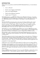
D-Link DI-701 Residential Gateway Technical Guide 1
FCC Certifications This equipment has been tested and found to comply with the limits for a Class B digital device, pursuant to Part 15 of the FCC Rules. These limits are designed to provide reasonable protection against harmful interference in a residential installation. This equipment generates, uses and can radiate radio frequency energy and, if not installed and used in accordance with the instructions, may cause harmful interference to radio communications.
LIMITED WARRANTY D-Link Systems, Inc. (“D-Link”) provides this limited warranty for its product only to the person or entity who originally purchased the product from D-Link or its authorized reseller or distributor.
conform to D-Link’s then current functional specifications for the Software, as set forth in the applicable documentation, from the date of original delivery of the Software for a period of ninety (90) days (“Warranty Period”), if the Software is properly installed on approved hardware and operated as contemplated in its documentation. D-Link further warrants that, during the Warranty Period, the magnetic media on which D-Link delivers the Software will be free of physical defects.
the product, or if the model or serial number has been altered, tampered with, defaced or removed; Initial installation, installation and removal of the product for repair, and shipping costs; Operational adjustments covered in the operating manual for the product, and normal maintenance; Damage that occurs in shipment, due to act of God, failures due to power surge, and cosmetic damage; and Any hardware, software, firmware or other products or services provided by anyone other than D-Link.
TABLE OF CONTENTS INTRODUCTION ............................................................................................................. 8 SAMPLE APPLICATION .............................................................................................. 10 HARDWARE .................................................................................................................... 11 HARDWARE CONNECTIONS .............................................................................................
TCP/IP NETWORK DIAGNOSIS ........................................................................................ 33 WINIPCFG................................................................................................................ 33 PING.EXE................................................................................................................. 34 Cable Connectivity Checkup...................................................................................... 34 Device Alive Checkup..........
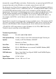
INTRODUCTION Thank you for your purchase of the D-Link DI-701 Residential Gateway. Its main features include: • Acts as a Firewall • Protects your Computers from Intruders • Share your Cable/DSL Modem • Works with any Ethernet Connection • Supports up to 32 Computers The DI-701 functions as an IEEE 802.3 Ethernet-based Residential Gateway.
dynamically assigned IP address and reboot. Each time they are powered up the DI-701 will recognize them and set their IP address to instantly connect them to the LAN. For advanced users Virtual Service support allows the DI-701 to provide limited visibility to local machines and their services as dictated by the user. An ISP provided IP address can be set to the DI-701 and then specific services can be rerouted to specific computers on the local network.
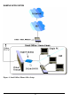
SAMPLE APPLICATION Figure 1: Small Office/ Home Office Setup 10
Hardware Table 1: Essential Hardware Item Included in Description Purpose UTP Ethernet cross-over cable Connects from local port of DI-701 to Ethernet Port on PC or Uplink port on Hub/Switch Power adapter Connects from DI-701 to power source DI-701 Main Unit CD Contains Quick Starter Guide and Setup Software 2 Manuals Quick Starter Guide and Detailed DI701 Technical Manual Description Connections Standard package Possible Additional Items From To (Not Included or Required) CAT3 or CAT5 UT
RS-232 cable Console Port COM port (For terminal program configuration only) A well-installed WAN environment (Cable Modem or ADSL Modem) HUB A well-installed LAN environment Hardware Connections Figure 2: Hardware Connections 1. Make sure your DI-701 is installed and connected properly. Use a UTP Ethernet crossover cable1 to connect the DSL/Cable Modem to the Global port. See Figure 2.
2. Use a CAT3 or CAT5 UTP Ethernet straight cable to connect the Local port to a free port on your hub or switch OR Use a CAT 3 or CAT5 Cross-Over cable to connect directly to a PC. 3. Connect the Power Adapter to the VDC IN port on the DI-701 and into a wall outlet. 4. Use an RS-232 cable to connect from a Serial port on the administrator computer to the Console port on the DI-701. (Optional - for terminal program configuration only.
Information from ISP If your IP address is provided dynamically by your ISP (Internet Service Provider), skip this step. If you have a static address from your ISP, gather the information shown in Table 3: Assigned Addresses and keep it for reference. Table 3: Assigned Addresses IP address ISP-assigning IP address Ex. 203.66.81.201 Subnet mask Ex. 255.255.255.0 Gateway Ex. 203.66.81.254 DNS server #1 Ex. 203.66.81.251 DNS server #2 Ex. 203.66.81.
CONFIGURATION SETTINGS Before Getting Started The DI-701 can be configured through the setup program provided, through a terminal emulation program, such as Windows HyperTerminal, or through Telnet. The DI-701 can be set with a range of options to allow it to function in most any network environment. The following sections cover a number of possible configuration settings. The key thing is to apply the instructions below to your desired configuration. Start by configuring a computer to access the DI-701.
Configuring in GUI Mode This section describes how to configure the DI-701 using the DI-701 Setup Software. Getting Started (GUI) 1. Insert the included setup CD into your CD-ROM drive. 2. The CD will auto run, click on the “Install DI-701 Setup Software” icon. 3. Once the Setup Software has been installed, go to StartàProgramsàD-Link DI-701. 4. When the following dialog box appears, click Find. Figure 4: DI-701 Setup Program 5. The setup program finds the DI-701.
Global Port Settings The Global Port settings are used to configure the port connected to your Cable/DSL modem. These should mirror the settings provided by your ISP. If your ISP provides a static IP address for your Internet connection, then select the “Set static global port configuration” radio button. You will need to fill in each field with appropriate information as provided by your ISP.
recommended you use the factory defaults settings for the “Continuous IP address pool starts at”. This field allows you to set the initial IP address that your clients will receive. For example, the first client to access the DI-701 will receive 192.168.0.2 for its address. “Number of IP addresses in pool” allows you to set the maximum number of clients you wish to use the DI-701 as a DHCP server. This should be set to either the number of clients you have or higher.
192.168.0.2). Is this example the gateway services would be offloaded to the DI-701. Management Select the Management tab to change the administrator password as shown in Figure 7. If your ISP requires that a Computer name be used to gain access to the Internet, enter the Computer name provided into the “Device/Computer Name” field.
Figure 8: Virtual Server 21
CHANGING PASSWORDS The DI-701 contains 2 passwords, one for standard user access and one for Super Admin access. Your ISP may have set Super Admin access if you purchased your unit through them, and should not be changed in this case. For all other users it is recommended that you change the default passwords to ensure that someone cannot adjust your settings without your knowledge.
type new password (0 to 8 characters) : ******** Type the new password (0-8 characters) and press re-type new password (0 to 8 characters) : ******** Re-type the new password (0-8 characters) and press Password has been changed. ADMIN>quit Type quit and press Bye ! D-Link DI-701, version 2.
CONFIGURATION IN TERMINAL PROGRAM MODE VIA HYPERTERMINAL OR TELNET You can use terminal emulation on your PC/workstation for the initial and future configuration of your DI-701. Windows HyperTerminal or other terminal emulation applications can be used. The following example was done with HyperTerminal. If you prefer, a telnet session can be opened directly. Telnet provides the same type of terminal emulation. For security purposes, the DI-701 uses port 333 for telnet.
Getting Started (Telnet) 1. Power up the DI-701. Wait 30-90 seconds for it to boot up. 2. In Windows 98 start Telnet by clicking StartàRun, type “telnet 192.168.0.1 333” and press enter. If the local port of the DI-701 is set to something other than “192.168.0.1” (the factory default), then simply use that IP address instead. The following information will appear: IP Sharing for Cable Modem/ADSL Modem/Ethernet BIOS Version: 1.00 (1999/10/06) ©Copyrights 1999, all rights reserved. SRAM Test ..........
Static Global Port Setting (TP) Example: Obtain configuration automatically ?(Yes/No) [Yes] :N2 IP address for 10M wan : [0.0.0.0]: 202.178.230.113 IP mask for 10M wan: [255.255.255.0] Device name (0 to 12 characters) : DI701 Default gateway Router [0.0.0.0]: 202.178.231.1 Primary DNS server [0.0.0.0]: 202.178.225.1 Secondary DNS server [0.0.0.0]: 202.178.244.207 New configuration will be: . . .
IP address for 10/100M LAN: [192.168.0.1] IP mask for 10/100M LAN: [255.255.255.0] Distribute configuration for PCs on LAN: [Yes] Distribute IP address pool start at: [192.168.0.2] DHCP IP address pool numbers: [32] Obtain configuration automatically: [No] IP address for 10M wan: [202.178.230.113] IP mask for 10M wan: [255.255.255.0] Device name: [DI701] Default gateways: [202.178.231.1] Primary DNS server: [202.178.225.1] Secondary DNS server: [202.178.244.
TROUBLESHOOTING Parts Names and Functions LED Indicators on the Front Panel Ports on the Rear Panel Figure 11: LED Indicators and Ports Table 4: LED Indicators and Connections LED Color Status Glowing Indicator Dim Flashing • Power Green Power On ‚ Local Link Green Connected to a LAN Disconnected from any Receiving/ device LAN device Sending data ƒ Local 100/10 Green 100Mbps detected 10Mbps detected N/A. „ Local Full/Half Green Full duplex Half duplex N/A.
Port Name Functions a VDC IN Connects the power adapter plug. b Console c Global d Local Connects an RS-232 serial cable to your computer for • Configuring from terminal programs • Firmware upgrade. Connects to Ethernet port on Cable Modem or DSL Modem for Internet Access. Connects to the Ethernet Hub/Switch on LAN. Cabling The most common problem associated with Ethernet is bad cabling. Make sure that all conected devices are turned on.
button on the bottom right and make sure your network adapter that is attached to the DI701 is selected in the Ethernet Adapter Information box. Look at the box labeled DHCP Server, this should be the DI-701's IP address (192.168.0.1 as default). If it is not, or it is blank or reads 255.255.255.255 then you may have a cabling problem (see above), or you may have another DHCP server on your network.
B. Choose the "Virtual Server" tab: C. Enter one of the port numbers that your application requires and then press the "Browse" button: D. Choose the computer that is using the application and press "Select": E. Press Add. Repeat this process for each individual port you need to open. F. Press Save. Your application should now work. It may be necessary to restart your application or your computer for the application to recognize the change.
TCP/IP Network Diagnosis Execute WINIPCFG.EXE or PING.EXE for TCP/IP network diagnosis. WINIPCFG The WINIPCFG program is used to gather information about the TCP/IP connections that are active on your system. It cannot be used to dynamically adjust TCP/IP connections. You can also renew leases (if allowed by the network), and get the current IP address assignments through this program. Go to Start. Click Run. Enter WINIPCFG. See Figure 12.
for a named resource are on top. The default gateway is the server to which the client connects to the Internet. The DHCP Server identifies the network server that assigns IP addresses to computers logging onto the network.
Device Alive Checkup Issue a PING command to the IP address of the device’s local port. The device and cable are working properly if it is successful. ISP Connectivity Checkup Issue a PING command to the IP address of your ISP’s Gateway or DNS server. You may need to check the settings in the DI-701 via the Windows GUI if this is dynamically set. For Example: C:\> PING 203.66.81.254 If successful, you can reach your ISP server.
Phone: 949-788-0805 (option #4) 36
TERMINAL COMMANDS You may type ? or help to list the main menu commands as below. command>help Internet SOAR version 1.
COMMANDS>passwd Old password: New password (4 characters or numbers at most): **** Re-type new password: **** show Displays the current configuration. For first-time login, the current configuration is the factory default settings. Refer to section titled “Factory Default Setting” for detail. Example: IP address of local port: [192.168.0.1] SubNetmask of local port: [255.255.255.0] Distribute IP addresses to local computers: [Yes] Continuous IP address pool starts at: [192.168.0.
Example: command>set Press if you agree with the default value, Or to escape. IP address of local port [192.168.0.1]: SubNetmask of local port [255.255.255.0]: Distribute IP address to local computers? (Yes/No) [Yes]: Continuous IP address pool start at [192.168.0.2]: Number of IP address in pool [32]: Obtain global port configuration from ISP? (Yes/No) [Yes]: n IP address of global port [202.178.230.149]: 203.66.99.252 SubNetmask of global port [255.255.255.
IP address of global port : [203.66.81.201] SubNetmask of global port : [255.255.255.0] Device name : [CABLE_ISP] Gateway : [203.66.81.254] Primary DNS server : [203.66.81.251] Secondary DNS server : [203.66.81.252] Save and reboot ?(Yes/No) : [No] vserv Displays the internal virtual server mapping. You can set (including add, delete) the applications’ names and the corresponding IP addresses of the local servers.
Input command : 1)Show 2)Add 3)Del 0)Quit: 1 Item Port(Application) Local server ==== ================= ================ 1. 80 (www) 192.168.0.12 2. 23 (telnet) 192.168.0.3 Example Del: Input command : 1)Show 2)Add 3)Del 0)Quit 3 Item Port(Application) Local server ==== ================= ================ 1. 80 (www) 192.168.0.12 2. 23 (telnet) 192.168.0.
renew You must renew the global port configuration, after you have released it, to enable the device. The ‘Show’ command enables you to see the configuration. The device will not work until you have renewed the global port configuration. Example: command>renew Update global port configuration Note that if you choose NOT to obtain the global port configuration from your ISP, this command won’t be executed and the following message will appear.
192.168.0.9 00E0-9810-9999 expired Luke 192.168.0.10 0080-C849-0882 expired MIA 192.168.0.11 00E0-9812-3456 0:35:54 ACER370 192.168.0.12 0040-0517-79BE 0:38:45 CT2 192.168.0.13 00E0-9811-2233 0:41:45 Roxy_gino 192.168.0.14 0040-3390-A1D9 expired mailen2 Total 13 users, 8 active leases.
Seq Flag client remote idle client fake remote ---+-----+---------------+------+------+---------------+-----+---1 0 07 192.168.0.12 1542 10583 212.234.161.21 2 05 192.168.0.13 4364 890 1269 10506 203.77.21.102 3 0 192.168.0.12 1541 10581 212.234.161.21 4 01 192.168.0.13 4000 90 1264 10253 205.188.153.98 5 120 0D 192.168.0.12 1476 10229 212.234.161.21 21 6 35 05 192.168.0.20 1086 10531 140.112.1.6 23 7 35 0D 192.168.0.12 1468 10218 212.234.161.21 21 8 0 0D 192.
Column Headings: IP client the IP address for the local computer Port client the port number for the local computer Port fake the translated port code from client port IP remote the IP address for the computer on Internet being accessed Port remote the port number for the remote computer Idle idle interval (in seconds) since last network frame transaction Super Admin Access The DI-701 supports a super-admin mode that is typically reserved by the ISP or other service provider.
System starts up D-Link IShare, version 2.00 Administrator password : command>set IP address of local port [192.168.0.1] : SubNetmask of local port [255.255.255.0] : Obtain global port configuraion from ISP ?(Yes/No) [Yes] : ( NOTE: Due to usrlimit command, the following lines will no longer appear in standard Admin mode, only Super Admin mode: “ Distribute IP addresses to local computers : [Yes] Continuous IP address pool starts at : [192.168.0.
Number of IP address in pool : [2] Obtain global port configuration from ISP : [Yes] Device name : [Untitled] Gateway : [192.152.81.100] Primary DNS server : [192.152.81.1] Secondary DNS server : [0.0.0.0] Resetting the BIOS In the case that you have forgotten your passwords, the DI-701 can be reset to factory defaults (command: Blank password, Super Admin:”year2000”) through the BIOS. For security reasons, the BIOS can only be reset using the console serial port.
FIRMWARE UPGRADE System Requirements • One free COM port on PC. • A pin-to-pin RS-232 cable. One end is 9 pin male connector, the other end is 9 or 25 pin female connector depends on the COM port. • FWLOAD.EXE : This is a DOS program for firmware upload. You can execute this file in Windows 95/98/NT or at DOS prompt. • FIRMWARE.BIN :This is a firmware image file. This file MUST reside in the same subdirectory with FWLOAD.EXE.
If any error message appears, check the cable connectivity and make sure that you have selected the correct COM port, then go through the steps again. Restart the DI-701 to activate the new firmware.
Index Assigned Addresses............................. 14 modifying settings............................... 18 Cable................................................... 36 passwd ................................................ 38 cabling .................................................. 2 PING................................................... 35 COM................................................... 23 release........................................... 42, 45 computer ..............................