D-Link DI-804HV Broadband Hardware VPN Router Manual Building Networks for People 07/25/2003
Contents Package Contents ................................................................................3 Introduction............................................................................................4 Getting Started ....................................................................................10 Using the Configuration Menu.............................................................. 11 Networking Basics ..............................................................................
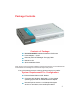
Package Contents Contents of Package: D-Link DI-804HV Broadband Hardware VPN Router Power Adapter – 5V DC Ethernet (CAT5-UTP/Straight-Through) Cable Manual on CD Quick Installation Guide Note: Using a power supply with a different voltage rating than the one included with the DI-804HV will cause damage and void the warranty for this product. If any of the above items are missing, please contact your reseller.
Introduction The D-Link DI-804HV is a 4-port Broadband Router with Virtual Private Network (VPN) functionality. It provides a complete solution for Internet surfing, office resources sharing, and secure access to remote corporate networks.. It is an ideal way to extend the reach and number of computers connected to your network. After completing the steps outlined in the Quick Installation Guide (included in your package) you will have the ability to share information and resources.
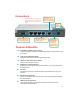
Connections All Ethernet ports auto-sense cable types to accommodate straight-through or cross-over cable. COM port provides serial connection for dial-up analog modem. WAN port is the connection for the Ethernet cable to the Cable or DSL modem LAN ports provide connections to Ethernetenabled devices. Features & Benefits Receptor for the Power Adapter Pressing the Reset Button restores the router to its original factory default settings.
Features & Benefits continued Access Control supported Allows you to assign different access rights for different users. Packet filter supported Packet Filter allows you to control access to a network by analyzing the incoming and outgoing packets and letting them pass or halting them based on the IP address of the source and destination. Virtual Server supported Enables you to expose WWW, FTP and other services on your LAN to be accessible to Internet users.
Introduction to Firewalls A firewall is a device that sits between your computer and the Internet that prevents unauthorized access to or from your network. A firewall can be a computer using firewall software or a special piece of hardware built specifically to act as a firewall. In most circumstances, a firewall is used to prevent unauthorized Internet users from accessing private networks or corporate LAN's and Intranets.
Introduction to Virtual Private Networking Virtual Private Networking (VPN) uses a publicly wired network (the Internet) to securely connect two different networks as if they were the same network. For example, an employee can access a corporate network from home using VPN, allowing the employee to access files, databases, and other networked resources. Here are several different implementations of VPN that can be used.
LEDS LED stands for Light-Emitting Diode. The DI-804HV has the following LEDs as described below: LED LED Activity Power A steady light indicates a connection to a power sourcea power source M1 LED Flashes once per second to indicate an active system M2 LED Lights up when the device has an Internet connection WAN A solid light indicates connection on the WAN port.
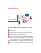
Getting Started 1 For additional information about setting up a network, see: 6 2 5 Networking Basics Using the Configuration Menu 4 3 For a typical network setup in a home or small office (as shown above), please do the following: You will need broadband Internet access (a Cable or DSL subscription line into your home or office). Consult with your Cable or DSL provider for proper installation of the modem.
Using the Configuration Menu Whenever you want to configure your network or the DI-804HV, you can access the Configuration Menu by opening the web-browser (i.e., Internet Explorer or Netscape Navigator) and typing in the IP Address of the DI-804HV. The DI-804HV default IP Address is shown below: Open the web browser Type in the IP Address of the DI-804HV (http://192.168.0.1) http://192.168.0.
Using the Configuration Menu Setup Wizard Once you have logged in, the Home screen will appear. Click Run Wizard The welcome screen outlines the steps to complete the setup wizard. Click Next to continue.
Using the Configuration Menu Setup Wizard > Set Password Click Next Old Password- This information is masked. New Password- Type in the new password for the admin account. Reconfirm- Type in the new password again to confirm. Click Next to continue with the Setup Wizard.
Using the Configuration Menu Setup Wizard > Time Zone Select the appropriate time zone for your locationSelect the proper time zone. Selections can be made by clicking on the drop down list. Click Next to continue. Click Next Setup Wizard > Connection Type (WAN) Select Your Internet ConnectionYou will be prompted to select the type of internet connection for your router. Choose the appropriate selection and click Next to continue.
Using the Configuration Menu Setup Wizard > Set Dynamic IP Address Click Next If your ISP uses Dynamic IP Address, this screen will appear: (Used mainly for Cable Internet service.) Host Name- Host name is the section where you input the name of your ISP. This section is optional and is not required to be filled in. MAC Address- Each network adapter has a discrete Media Access Control (MAC) address. Note that some computer and peripherals may already include built-in network adapter.
Using the Configuration Menu Setup Wizard > Set Static IP Address Click Next If your ISP uses a Static IP Address, and this option is selected, then this screen will appear. WAN IP Address- If your ISP requires a Static IP Address, and this option is selected, then this screen appear. Enter the IP address information originally provided to you by your ISP. You will need to complete all the required fields. WAN Subnet Mask- The subnet for the DI-804HV is preconfigured to 255.255.255.0.
Using the Configuration Menu Setup Wizard > PPPoE Click Next If your ISP uses PPPoE (Point-to-Point Protocol over Ethernet), and this option is selected, then this screen will appear: (Used mainly for DSL Internet service.) PPPoE Account- Enter in the username provided to you by your ISP. PPPoE Password- Enter in the password provided to you by your ISP. PPPoE Service Name- Enter in the name of your service provider. This is an optional field and is not necessary to be filled in.
Using the Configuration Menu Setup Wizard Click Next Configure this section only if you have an analog dial-up account. Otherwise click Next to skip. Dial-up Telephone- Enter the telephone number to connect to your ISP. Dial-up Account- This information is provided by your ISP. The Dial-up Account is also known as username. Dial-up Password- Enter in the password to log into your Dial-up account. Primary DNS- The Primary DNS can be found by contacting the ISP.
Using the Configuration Menu Setup Wizard Click Restart Back- Click on Back button to go back to previous page. Restart- Click on Restart button to finalize the settings made. Exit- Click on Exit button to end the Setup Wizard without saving any changes.
Using the Configuration Menu Home > WAN Choose WAN Type WAN stands for Wide Area Network. In this case WAN represents the mode in which you connect to the Internet.
Using the Configuration Menu Home > WAN > Dynamic IP Address Most Cable modem users will select this option to obtain an IP Address automatically from their ISP (Internet Service Provider). Host Name- This is optional, but may be required by some ISPs. The host name is the device name of the Router. MAC Address- The default MAC Address is set to the WAN’s physical interface MAC address on the Router.
Using the Configuration Menu Home > WAN > Static IP Address If you use a Static IP Address, you will input information here that your ISP has provided to you. IP Address- Input the IP Address provided by your ISP Subnet Mask- Input the Subnet Mask provided by your ISP ISP Gateway Address- Input the Gateway address provided by your ISP Primary DNS Address- Input the primary DNS address provided by your ISP Secondary DNS AddressMTU- (Optional) Input the Secondary DNS address provided by your ISP.
Using the Configuration Menu Home > WAN > PPPoE Most DSL users will select this option to obtain an IP address automatically from their ISP through the use of PPPoE. User Name- Your PPPoE username provided by your ISP Password- Your PPPoE password is provided by your ISP Service Name- (Optional) Check with your ISP for more information if they require the use of service name. IP Address- (Optional) Enter in the IP Address if you are assigned a static PPPoE address.
Using the Configuration Menu Home > WAN > Dial-up Network Most Dial-up users will select this option to connect to their ISP through an analog dial-up modem. This feature can be used as a back-up when your broadband connectivity is unavailable. Dial-up Telephone - Telephone number to connect to your ISP Dial-up Account- Username provided by your ISP Dial-up Password- Password provided by your ISP Primary DNSSeconday DNS- If the settings are configured as “0.0.0.
Using the Configuration Menu Home > WAN > PPTP Point-to-Point Tunneling Protocol (PPTP) is a WAN connection used in Europe.
Using the Configuration Menu Home > WAN > BigPond Cable Dynamic IP Address for BigPond is a WAN connection used in Australia. User Name- Enter in the username for the BigPond account Password- Enter the password for the BigPond account Login Server IP- (Optional) enter the Login Server name if required Renew IP forever- If enabled, the device will automatically connect to your ISP after your unit is restarted or when the connection is dropped.
Using the Configuration Menu Home > LAN LAN (Local Area Network). This is considered your internal network. These are the IP settings of the LAN interface for the DI804HV. These settings may be referred to as Private settings. You may change the LAN IP address if needed. The LAN IP address is private to your internal network and cannot be seen on the Internet. LAN IP Address- The IP address of the LAN interface. The default IP address is: 192.168.0.1 Subnet Mask- The subnet mask of the LAN interface.
Using the Configuration Menu Home >DHCP DHCP stands for Dynamic Host Control Protocol. The DI-804HV has a built-in DHCP server. The DHCP Server will automatically assign an IP address to the computers on the LAN/private network. Be sure to set your computers to be DHCP clients by setting their TCP/IP settings to “Obtain an IP Address Automatically.” When you turn your computers on, they will automatically load the proper TCP/IP settings provided by the DI-804HV.
Using the Configuration Menu Home >VPN Settings VPN Settings are settings that are used to create virtual private tunnels to remote VPN gateways. The tunnel technology supports data confidentiality, data origin, authentication and data integrity of network information by utilizing encapsulation protocols, encryption algorithms, and hashing algorithms. VPN - Check here to enable VPN tunnels. When you are not using the VPN feature, it is best to keep VPN disabled.
Using the Configuration Menu Home >VPN Settings > Tunnel > Method>IKE Tunnel Name- Current tunnel name. Aggressive Mode- Enabling this mode will accelerate establishing tunnel, but the device will have less security. Local Subnet- The subnet of the VPN gateway’s local network. It can be a host, a partial subnet or a whole subnet. Local Netmask- Local netmask combined with local subnet to form a subnet domain. Remote Subnet- The subnet of the remote VPN gateway’s local network.
Using the Configuration Menu Home >VPN Settings > Tunnel > Method > IKE > Select IKE Proposal IKE Proposal index- A list of selected proposal indexes from the IKE proposal pool listed below. Proposal Name- This is the name used to classify the IKE proposal. DH Group- There are three groups can be selected: group 1 (MODP768), group 2 (MODP1024), group 5 (MODP1536). Encrypt algorithm- There are two algorithms that can be selected: 3DES and DES.
Using the Configuration Menu Home >VPN Settings > Tunnel > Method > IKE > Select IKE Proposal Continued... Life Time- Enter in the life time value. Life Time Unit- There are two units that can be selected: second and KB. Proposal ID- The identifier of IKE proposal can be chosen for adding corresponding proposal to the dedicated tunnel. Add to- Click it to add the chosen proposal indicated by proposal ID to IKE Proposal index list.
Using the Configuration Menu Home >VPN Settings > Tunnel > Method > IKE > Select IPSEC Proposal IPSec Proposal index- A list of selected proposal indexes from the IPSec proposal pool listed below. Proposal Name- This is the name used to classify the IPSec Proposal DH Group- There are three groups that can be selected: group 1 (MODP768), group 2 (MODP1024), group 5 (MODP1536). Encap protocol- There are two protocols that can be selected: ESP and AH.
Using the Configuration Menu Home >VPN Settings > Tunnel > Method > IKE > Select IPSEC Proposal Continued... Life Time- Enter in a life time value. Life Time Unit- There are two units that can be selected: second and KB. Proposal ID- The identifier of IPSec proposal can be chosen for adding the proposal to the dedicated tunnel. Add to- Click it to add the chosen proposal indicated by proposal ID to IPSec Proposal index list.
Using the Configuration Menu Home >VPN Settings > Tunnel > Manual Tunnel Name- Current tunnel name. Aggressive Mode- Enabling this mode will accelerate establishing tunnel, but the device will have less security. Local Subnet- The subnet of the VPN gateway’s local network. It can be a host, a partial subnet or a whole subnet. Local Netmask- Local netmask combined with local subnet to form a subnet domain. Remote Subnet- The subnet of the remote VPN gateway’s local network.
Using the Configuration Menu Home >VPN Settings > Tunnel > Manual Continued... Encapsulation Protocol- There are two protocols that can be selected: ESP and AH. Encryption Algorithm- There are two algorithms that can be selected: 3DES and DES. Encryption KeyAuthentication Algorithm- For DES, the encryption key is 8 bytes (16 Char.). For 3DES, the encryption key is 24 bytes (48 Char.). There are two algorithms that can be selected: SHA1 and MD5.
Using the Configuration Menu Home >VPN Settings > Dynamic VPN Tunnel VPN Settings - IKE- There are three parts that are necessary to setup the configuration of IKE for the dedicated tunnel: basic setup, IKE proposal setup, and IPSec proposal setup. Basic setup includes the setting of following items: local subnet, local netmask, remote subnet, remote netmask, remote gateway, and pre-shared key. The tunnel name is derived from previous page of VPN setting.
Using the Configuration Menu Home >VPN Settings > Dynamic VPN Tunnel Continued... Preshared Key- The first key that supports IKE mechanism of both VPN gateways for negotiating further security keys. The preshared key must be the same for both endpoint gateways. IKE Proposal index- Click the button to setup a set of frequent-used IKE proposals and select from the set of IKE proposals for the dedicated tunnel.
Using the Configuration Menu Home >VPN Settings > Dynamic VPN Tunnel > Set IKE Proposal IKE Proposal index- A list of selected proposal indexes from the IKE proposal pool listed below. Proposal Name- It indicates which IKE proposal to be focused. First char of the name with 0x00 value stands for the IKE proposal is not available. DH Group- There are three groups can be selected: group 1 (MODP768), group 2 (MODP1024), group 5 (MODP1536).
Using the Configuration Menu Home >VPN Settings > Dynamic VPN Tunnel > Set IKE Proposal Continued... Life Time- Enter in the life time value. Life Time Unit- There are two units that can be selected: second and KB. Proposal ID- The identifier of IKE proposal can be chosen for adding corresponding proposal to the dedicated tunnel. Add to- Click it to add the chosen proposal indicated by proposal ID to IKE Proposal index list.
Using the Configuration Menu Home >VPN Settings > Dynamic VPN Tunnel > Set IPSEC Proposal IPSec Proposal index- A list of selected proposal indexes from the IPSec proposal pool listed below. Proposal Name- This is the name used to classify the IPSec proposal. DH Group- There are three groups that can be selected: group 1 (MODP768), group 2 (MODP1024), group 5 (MODP1536). Encap protocol- There are two protocols that can be selected: ESP and AH.
Using the Configuration Menu Home >VPN Settings > Dynamic VPN Tunnel > Set IPSEC Proposal Continued... Life Time- Enter in a life time value. Life Time Unit- There are two units that can be selected: second and KB. Proposal ID- The identifier of IPSec proposal can be chosen for adding the proposal to the dedicated tunnel. Add to- Click it to add the chosen proposal indicated by proposal ID to IPSec Proposal index list.
Using the Configuration Menu Home >VPN Settings > L2TP Server Setting Enable L2TP Server- Click to enable the L2TP Server function. Virtual IP of L2TP Enter your Virtual IP address to access the L2PT server. ServerAuthentication Protocol- Select one of the following authentication protocols: PAP, CHAP, MSCHAP. Tunnel Name- Current tunnel name. User Name- Enter in the username for the L2TP account. Password- Enter in the password for the L2TP account.
Using the Configuration Menu Home >VPN Settings >PPTP Server Setting Enable PPTP Server- Click to enable the PPTP Server function. Virtual IP of PPTP Enter your Virtual IP address to access thePPPT server. ServerAuthentication Protocol- Select one of the following authentication protocols: PAP, CHAP, MSCHAP. Tunnel Name- Current tunnel name. User Name- Enter in the username for the PPTP account. Password- Enter in the password for the PPTP account.
Using the Configuration Menu Advanced > Virtual Server The DI-804HV can be configured as a virtual server so that remote users accessing Web or FTP services via the public IP address can be automatically redirected to local servers in the LAN (Local Area Network). The DI-804HV firewall feature filters out unrecognized packets to protect your LAN network so all computers networked with the DI-804HV are invisible to the outside world.
Using the Configuration Menu Advanced > Application Some applications require multiple connections, such as Internet gaming, video conferencing, Internet telephony and others. These applications have difficulties working through NAT (Network Address Translation). Special Applications makes some of these applications work with the DI-804HV.
Using the Configuration Menu Advanced > IP Filter Use IP (Internet Protocol) filters to allow or deny computers access to the Internet based on their IP address. IP FilterUse IP Filters to deny LAN IP addresses access to the internet Enabled or DisabledClick Enabled to apply the filter policy or click Disabled to enter an inactive filter policy (You can reactivate the policy later.) IP AddressEnter in the IP address range of the computers that you want the policy to apply to.
Using the Configuration Menu Advanced > MAC Filters MAC (Media Access Control) Filters are used to deny or allow LAN (Local Area Network) computers from accessing the Internet and network by their MAC address. At the bottom of the screen, there is a list of MAC addresses from the DHCP client computers connected to the DI-804HV. To use them, select one from the drop down list. Then click the “Apply” button and the DI-804HV will fill in the appropriate information to the list.
Using the Configuration Menu Advanced > URL Blocking Use URL Blocking to deny LAN computers from accessing specific web sites by its URL. A URL is a specially formatted text string that defines a location on the Internet. If any part of the URL contains the blocked word, the site will not be accessible and the web page will not display. Disabled URL BlockingSelect this option if you do not want to use URL Blocking.
Using the Configuration Menu Advanced > Domain Blocking Use Domain Blocking to allow or deny computers access to specific Internet domains whether it is through www, ftp, snmp, etc. Disabled Domain BlockingSelect this option if you do not want to use Domain Blocking. Allow users to access all domains except “Blocked Domains”Select this option to allow users to access the specified Internet domains listed below. Users will be denied access to all other Internet domains.
Using the Configuration Menu Advanced > Firewall Firewall Rules is an advance feature used to deny or allow traffic from passing through the device. It works in the same way as IP Filters with additional settings. You can create more detailed rules for the device. Enabled or DisabledClick Enabled to apply the filter policy or click Disabled to enter an inactive filter policy (You can reactivate the policy later). NameEnter the name of the Firewall Rule.
Using the Configuration Menu Advanced > Firewall Continued IP AddressEnter in the IP address range of the computers that you want the policy to apply to. If it is only a single computer that you want the policy applied to, then enter the IP address of that computer in the Start Source IP and leave the End Source IP blank. ProtocolSelect one of the following protocols: TCP, UDP, or ICMP Port RangeEnter in the port range of the TCP/UDP ports that you want the policy to apply to.
Using the Configuration Menu Advanced > SNMP SNMP (Simple Network Management Protocol) is a widely used network monitoring and control protocol that reports activity on each network device to the administrator of the network. SNMP can be used to monitor traffic and statistics of the DI-804HV.
Using the Configuration Menu Tools > DDNS DDNS (Dynamic Domain Name System) keeps dynamic IP addresses (e.g., IP addresses assigned by a DHCP capable router or server) linked to a domain name. Users who have a Dynamic DNS account may use this feature on the DI-804HV. DDNS- When an IP address is automatically assigned by a DHCP server, DDNS automatically updates the DNS server.
Using the Configuration Menu Advanced > Routing Dynamic Routing- Dynamic Routing Settings allow the VPN Router to route IP packets to another network automatically. The RIP protocol is applied, and broadcasts the routing information to other routers on the network regularly. By default, it is set to disable. Check to enable (RIPv1 / RIPv2) protocol. RIP v1- Protocol in which the IP address is routed through the internet.
Using the Configuration Menu Advanced > DMZ If you have a computer that cannot run Internet applications properly from behind the DI-804HV, then you can allow that computer to have unrestricted Internet access. Enter the IP address of that computer as a DMZ (Demilitarized Zone) host with unrestricted Internet access. Adding a client to the DMZ may expose that computer to a variety of security risks; so only use this option as a last resort.
Using the Configuration Menu Tools> Admin You can change the admin and user passwords here. It is recommended that you change the admin password from the default setting. The default passwords are blank (no password). Password- Remote Management- IP Address- Port- To change the passwords, enter the new password twice to confirm. Remote Management allows the device to be configured through the WAN (Wide Area Network) port from the Internet using a web browser.
Using the Configuration Menu Tools> Time Set the time here by entering it manually or use NTP (Network Time Protocol.) NTP is standard protocol on the Internet that synchronizes the time settings accurately for the DI-804HV. Enable NTP- Select to enable NTP and synchronize the time settings on your network using an NTP server Default NTP server- If you are enabling NTP, please enter the link to the default server.
Using the Configuration Menu Tools > System The current system settings can be saved as a file onto the local hard drive. The saved file or any other saved setting file created by the DI-804HV can be uploaded into the unit. To reload a system settings file, click on Browse to search the local hard drive for the file to be used. The device can also be reset back to factory default settings by clicking on the Reset to Default button. Use the restore feature only if necessary.
Using the Configuration Menu Tools > Firmware You can upgrade the firmware by using this tool. First, check the D-Link support site for firmware updates at http://support.dlink.com. Make sure that the firmware you want to use is saved on the local hard drive of your computer. Click on Browse to search the local hard drive for the firmware that you downloaded from the D-Link website to be used for the update.
Using the Configuration Menu Tools > Misc Ping Test- In the open box, enter an URL (i.e. www.dlink.com) or an IP address and click on Ping to test your internet connection. Restart Device- Click Reboot to restart the unit. Block WAN Ping- Click Enable to block the WAN ping. Computers on the Internet will not get a reply back from the DI-804HV when it is being “ping”ed. This may help to increase security.
Using the Configuration Menu Tools > Misc Continued... UPnP- UPnP is short for Universal Plug and Play which is a networking architecture that provides compatibility among networking equipment, software, and peripherals. The DI-804HV is a UPnP enabled router and will only work with other UPnP devices/softwares. If you do not want to use the UPnP Functionality, it can be disabled by selecting “Disabled”.
Using the Configuration Menu Status > Device Info This screen displays information about the DI-804HV DHCP Renew- Click to refresh IP addresses sent from the DHCP server. DHCP Release- Click to release IP addreses sent from the DHCP server.
Using the Configuration Menu Status > Log This screen displays activities occurring on the DI-804HV. First Page- Click First Page to go to the first page of the log. Last Page- Click Last Page to go to the last page of the log. Previous- Click Previous to go to the previous page of the log. Next- Click Next to go to the next page of the log. Clear- Click Clear to clear the current page of the log. Log Settings- Click for advanced features (see next page.
Using the Configuration Menu Status > Log Settings E-Mail Alert- The DI-804HV can be set up to send the log files to a specific email address. SMTP Server IP- Enter in the IP address of the mail server. Email Address- Enter in the email address of the recipient who will receive the email log. Send Mail Now- Click to send mail immediately. IP Address of the Syslog Server- Enter in the IP address of a syslog server within the network. Click Enable to activate the policy.
Using the Configuration Menu Status > Stats In Stats section, traffic statistics are displayed. Refresh- This will update the page. Reset- This will reset the packet counter to zero. WAN- Displays Received / Transmitted packets from the WAN port. LAN- Displays Received / Transmitted packets from the LAN port.
Using the Configuration Menu Help This screen displays the complete Help menu. For help at anytime, click the Help tab in the Configuration menu.
Networking Basics Using the Network Setup Wizard in Windows XP In this section you will learn how to establish a network at home or work, using Microsoft Windows XP. Note: Please refer to websites such as http://www.homenethelp.com and http://www.microsoft.com/windows2000 for information about networking computers using Windows 2000, ME or 98. Go to Start>Control Panel>Network Connections Select Set up a home or small office network When this screen appears, Click Next.
Networking Basics Please follow all the instructions in this window: Click Next In the following window, select the best description of your computer. If your computer connects to the internet through a gateway/router, select the second option as shown.
Networking Basics Enter a Computer description and a Computer name (optional.) Click Next Enter a Workgroup name. All computers on your network should have the same Workgroup name.
Networking Basics Please wait while the Network Setup Wizard applies the changes. When the changes are complete, click Next. Please wait while the Network Setup Wizard configures the computer. This may take a few minutes.
Networking Basics In the window below, select the option that fits your needs. In this example, Create a Network Setup Disk has been selected. You will run this disk on each of the computers on your network. Click Next. Insert a disk into the Floppy Disk Drive, in this case drive A.
Networking Basics Please read the information under Here’s how in the screen below. After you complete the Network Setup Wizard you will use the Network Setup Disk to run the Network Setup Wizard once on each of the computers on your network. To continue click Next.
Networking Basics Please read the information on this screen, then click Finish to complete the Network Setup Wizard. The new settings will take effect when you restart the computer. Click Yes to restart the computer. You have completed configuring this computer. Next, you will need to run the Network Setup Disk on all the other computers on your network. After running the Network Setup Disk on all your computers, your new wireless network will be ready to use.
Networking Basics Naming your Computer To name your computer, please follow these directions: In Windows XP: Click Start (in the lower left corner of the screen) Right-click on My Computer Select Properties and click Select the Computer Name Tab in the System Properties window. You may enter a Computer Description if you wish; this field is optional. To rename the computer and join a domain, Click Change.
Networking Basics Naming your Computer In this window, enter the Computer name Select Workgroup and enter the name of the Workgroup All computers on your network must have the same Workgroup name. Click OK OK Checking the IP Address in Windows XP The wireless adapter-equipped computers in your network must be in the same IP Address range (see Getting Started in this manual for a definition of IP Address Range.
Networking Basics Checking the IP Address in Windows XP This window will appear. Click the Support tab Click Close Assigning a Static IP Address in Windows XP/2000 Note: Residential Gateways/Broadband Routers will automatically assign IP Addresses to the computers on the network, using DHCP (Dynamic Host Configuration Protocol) technology. If you are using a DHCP-capable Gateway/Router you will not need to assign Static IP Addresses.
Networking Basics Assigning a Static IP Address in Windows XP/2000 Double-click on Network Connections Right-click on Local Area Connections Click on Properties 78
Networking Basics Assigning a Static IP Address in Windows XP/2000 Click on Internet Protocol (TCP/IP) Click Properties In the window below, input your IP address, subnet mask, default gateway and DNS server address. (The IP Addresses on your network must be within the same range. For example, if one computer has an IP Address of 192.168.0.2, the other computers should have IP Addresses that are sequential, like 192.168.0.3 and 192.168.0.4.
Networking Basics Assigning a Static IP Address with Macintosh OSX Go to the Apple Menu and select System Preferences cClick on Network Select Built-in Ethernet in the Show pull-down menu Select Manually in the Configure pull-down menu Input the Static IP Address, the Subnet Mask and the Router IP Address in the appropriate fields Click Apply Now 80
Networking Basics Selecting a Dynamic IP Address with Macintosh OSX Go to the Apple Menu and select System Preferences Click on Network Select Built-in Ethernet in the Show pull-down menu Select Using DHCP in the Configure pull-down menu Click Apply Now The IP Address, Subnet mask, and the Router’s IP Address will appear in a few seconds 81
Networking Basics Adding and Sharing Printers in Windows XP After you have run the Network Setup Wizard on all the computers in your network (please see the Network Setup Wizard section at the beginning of Networking Basics,) you can use the Add Printer Wizard to add or share a printer on your network.
Networking Basics Adding a local printer (a printer connected directly to a computer) A printer that is not shared on the network and is connected directly to one computer is called a local printer. If you do not need to share your printer on a network, follow these directions to add the printer to one computer.
Networking Basics Adding a local printer Click Next Select Local printer attached to this computer (Deselect Automatically detect and install my Plug and Play printer if it has been selected.) Click Next Select Use the following port: From the pull-down menu select the correct port for your printer (Most computers use the LPT1: port, as shown in the illustration.
Networking Basics Adding a local printer Select and highlight the correct driver for your printer. Click Next (If the correct driver is not displayed, insert the CD or floppy disk that came with your printer and click Have Disk.) At this screen, you can change the name of the printer (optional.) Click Next Select Yes, to print a test page. A successful printing will confirm that you have chosen the correct driver.
Networking Basics Adding a local printer This screen gives you information about your printer.
Networking Basics Adding a local printer Go to Start> Printers and Faxes A successful installation will display the printer icon as shown at right. You have successfully added a local printer. Sharing a network printer After you have run the Network Setup Wizard on all the computers on your network, you can run the Add Printer Wizard on all the computers on your network.
Networking Basics Sharing a network printer Click on Add a printer Click Next Select Network Printer Click Next 88
Networking Basics Sharing a network printer Select Browse for a printer Click Next Select the printer you would like to share Click Next Click Finish 89
Networking Basics Sharing a network printer To check for proper installation: Go to Start > Printers and Faxes The printer icon will appear at right, indicating proper installation. You have completed adding the printer.
Networking Basics Sharing an LPR printer To share an LPR printer (using a print server,) you will need a Print Server such as the DP-101P+. Please make sure that you have run the Network Setup Wizard on all the computers on your network. To share an LPR printer, please follow these directions: Go to Start > Printers and Faxes Click on Add a Printer The screen to the right will appear Click Next Select Local Printer...
Networking Basics Sharing an LPR printer This screen will show you information about your printer. Click Finish Select the printer you are adding from the list of Printers. Insert the printer driver disk that came with your printer.
Networking Basics Sharing an LPR printer You can rename your printer if you choose. It is optional. Please remember the name of your printer. You will need this information when you use the Add Printer Wizard on the other computers on your network. Click Next Select Yes, to print a test page. Click Next This screen will display information about your printer. Click Finish to complete the addition of the printer.
Resetting the DI-804HV to the Factory Default Settings After you have tried other methods for troubleshooting your network, you may choose to Reset the DI-804HV to the factory default settings. To hard-reset the D-Link DI-804HV to the Factory Default Settings, please do the following: Locate the Reset button on the back of the DI-804HV Use a paper clip to press the Reset button and power on. Hold for about 5 seconds (don’t hold too long) and then release. (Or, release when M1 and M2 flash at the same time.
Technical Specifications Standards IEEE 802.3 10BASET-T Ethernet IEEE 802.3u 100BASE-TX Fast Ethernet IEEE 802.3x Flow Control ANSI/IEEE 802.3 NWay auto-negotiation VPN Pass Through Function PPTP L2TP IPSec Device Management LEDs Web-Based – Internet Explorer 6x or later; Netscape Navigator 6x or later; or other Java- enabled browsers. WAN LAN M1 M2 COM Operating Temperature 41°F to 131°F ( 5°C to 55°C) Humidity 10-90% Power DC 5V Dimensions L = 7.56 inches (192mm) W = 4.65 inches (48mm) H = 1.
Frequently Asked Questions Why can´t I access the web based configuration? When entering the IP Address of the DI-804HV (192.168.0.1), you are not connecting to the Internet or have to be connected to the Internet. The device has the utility builtin to a ROM chip in the device itself. Your computer must be on the same IP subnet to connect to the web-based utility. To resolve difficulties accessing a web utility, please follow the steps below.
Frequently Asked Questions (continued) Why can´t I access the web based configuration? (continued) What type of cable should I be using? (continued) What´s the difference between a crossover cable and a straight-through cable? The wiring in crossover and straight-through cables are different. The two types of cable have different purposes for different LAN configurations. EIA/TIA 568A/568B define the wiring standards and allow for two different wiring color codes as illustrated in the following diagram.
Frequently Asked Questions (continued) Why can´t I access the web based configuration? (continued) Step 2 Disable any Internet security software running on the computer. Software firewalls like Zone Alarm, Black Ice, Sygate, Norton Personal Firewall, etc. might block access to the configuration pages. Check the help files included with your firewall software for more information on disabling or configuring it. Step 3 Configure your Internet settings. Go to Start>Settings>Control Panel.
Frequently Asked Questions (continued) Why can´t I access the web based configuration? (continued) Step 4 Check your IP Address. Your computer must have an IP Address in the same range of the device you are attempting to configure. Most D-Link devices use the 192.168.0.X range. How can I find my IP Address in Windows 95, 98, or ME? Step 1 Click on Start, then click on Run. Step 2 The Run Dialogue Box will appear. Type winipcfg in the window as shown then click OK.
Frequently Asked Questions (continued) Why can´t I access the web based configuration? (continued) Step 4 (continued) Check your IP Address. Your computer must have an IP Address in the same range of the device you are attempting to configure. Most D-Link devices use the 192.168.0.X range. How can I find my IP Address in Windows 2000/XP? Step 1 Click on Start and select Run. Step 2 Type cmd then click OK. Step 3 From the Command Prompt, enter ipconfig.
Frequently Asked Questions (continued) Why can´t I access the web based configuration? (continued) Step 4 (continued) Check your IP Address. Your computer must have an IP Address in the same range of the device you are attempting to configure. Most D-Link devices use the 192.168.0.X range. Make sure you take note of your computer´s Default Gateway IP Address. The Default Gateway is the IP Address of the D-Link router. By default, it should be 192.168.0.1.
Frequently Asked Questions (continued) Why can´t I access the web based configuration? (continued) How can I assign a Static IP Address in Windows 2000? (continued) Click Use the following IP Address and enter an IP Address that is on the same subnet as the LAN IP Address on your router. Example: If the router´s LAN IP Address is 192.168.0.1, make your IP Address 192.168.0.X where X = 2-99. Make sure that the number you choose is not in use on the network.
Frequently Asked Questions (continued) Why can´t I access the web based configuration? (continued) How can I assign a Static IP Address in Windows 98/Me? (continued) Step 2 Click Specify an IP Address. Enter in an IP Address that is on the same subnet as the LAN IP Address on your router. Example: If the router´s LAN IP Address is 192.168.0.1, make your IP Address 192.168.0.X where X is between 2-99. Make sure that the number you choose is not in use on the network. Step 3 Click on the Gateway tab.
Frequently Asked Questions (continued) How can I setup my router to work with a Cable modem connection? Dynamic Cable connection (IE AT&T-BI, Cox, Adelphia, Rogers, Roadrunner, Charter, and Comcast). Note: Please configure the router with the computer that was last connected directly to the cable modem. Step 1 Log into the web based configuration by typing in the IP Address of the router (default:192.168.0.1) in your web browser. The username is admin (all lowercase) and the password is blank (nothing).
Frequently Asked Questions (continued) How can I setup my router to work with a Cable modem connection? (continued) Step 3 Power cycle the cable modem and router: Turn the cable modem off (first) . Turn the router off Leave them off for 2 minutes.** Turn the cable modem on (first). Wait until you get a solid cable light on the cable modem. Turn the router on. Wait 30 seconds. ** If you have a Motorola (Surf Board) modem, leave off for at least 5 minutes.
Frequently Asked Questions (continued) How can I setup my router to work with Earthlink DSL or any PPPoE connection? Make sure you disable or uninstall any PPPoE software such as WinPoet or Enternet 300 from your computer or you will not be able to connect to the Internet. Step 1 Upgrade Firmware if needed. (Please visit the D-Link tech support website at: http://support.dlink.com for the latest firmware upgrade information.) Step 2 Take a paperclip and perform a hard reset.
Frequently Asked Questions (continued) How can I setup my router to work with Earthlink DSL or any PPPoE connection? (continued) Step 8 Click Apply. When prompted, click Continue. Once the screen refreshes, unplug the power to the D-Link router. Step 9 Turn off your DSL modem for 2-3 minutes. Turn back on. Once the modem has established a link to your ISP, plug the power back into the D-Link router. Wait about 30 seconds and log back into the router.
Frequently Asked Questions (continued) How can I set up my router to work with another DI-804HV router? Step 1 Log into the web based configuration of the router by typing in the IP address of the router (default: 192.168.0.1) in your web browser. By default the username is “admin” and there is no password. Step 2 Click the VPN button on the left column, select the checkbox to Enable the VPN, and then in the box next to Max.
Frequently Asked Questions (continued) How can I set up my router to work with another DI-804HV router? (continued) Step 4 In the Local Subnet and Local Netmask fields enter the network identifier for the local DI-804HV´s LAN and the corresponding subnet mask. Step 5 In the Remote Subnet and Remote Netmask fields enter the network identifier for the remote DI804HV´s LAN and the corresponding subnet mask.
Frequently Asked Questions (continued) How can I set up my router to work with another DI-804HV router? (continued) Step 8 Enter a name for proposal ID number 1 and select Group 1, 2, or 5 from the DH Group dropdown menu. Step 9 Select DES or 3DES as the Encryption Algorithm and either SHA-1 or MD5 as the Authentication Algorithm. Step 10 Enter a Lifetime value and then either select Sec. or KByte as the unit for the lifetime value.
Frequently Asked Questions (continued) How can I set up my router to work with another DI-804HV router? (continued) Step 11 Select 1 out of the Proposal ID dropdown menu and click Add To, which will add the proposal that was just configured to the IKE Proposal Index. Click Apply and then click Back. Step 12 Click on Select IPSec Proposal... Step 13 Enter a name for proposal ID number 1 and select Group 1, 2, 5, or None from the DH Group dropdown menu.
Frequently Asked Questions (continued) How can I set up my router to work with another DI-804HV router? (continued) Step 15 Select DES or 3DES as the Encryption Algorithm and either SHA-1, MD5, or None as the Authentication Algorithm. Step 16 Enter a Lifetime value and then either select Sec. or KB as the unit for the lifetime value. Step 17 Select 1 out of the Proposal ID dropdown menu and click Add To, which will add the proposal that was just configured to the IPSec Proposal Index.
Frequently Asked Questions (continued) How can I set up my router to work with another DI-804HV router? (continued) Step 18 Follow these instructions to configure your Other DI-804HV using the exact same settings for the IKE Proposal and the IPSec Proposal.
Frequently Asked Questions (continued) How can I set up my router to work with a DI-804V router? (continued) Step 3 In the space provided, enter the Tunnel Name for ID number 1, select IKE, and then click More. Step 4 In the Local Subnet and Local Netmask fields enter the network identifier for DI-804HV´s LAN and the corresponding subnet mask. Step 5 In the Remote Subnet and Remote Netmask fields enter the network identifier for the DI-804V´s LAN and the corresponding subnet mask.
Frequently Asked Questions (continued) How can I set up my router to work with a DI-804V router? (continued) Step 6 In the Remote Gateway field enter the WAN IP address of the remote DI-804V and in the Preshared Key field, enter a key which must be exactly the same as the Preshared Key that is configured on the DI-804V. Step 7 Click Apply and then click on Select IKE Proposal... Step 8 Enter a name for proposal ID number 1 and select Group 2 from the DH Group drop down menu.
Frequently Asked Questions (continued) How can I set up my router to work with a DI-804V router? (continued) Step 11 Select 1 out of the Proposal ID dropdown menu and click Add To, which will add the proposal that was just configured to the IKE Proposal Index. Click Apply and then click Back. Step 12 Click on Select IPSec Proposal... Step 13 Enter a name for proposal ID number 1 and select None from the DH Group dropdown menu. Step 14 Select ESP as the Encapsulation Protocol.
Frequently Asked Questions (continued) How can I set up my router to work with a DI-804V router? (continued) Step 17 Select 1 out of the Proposal ID dropdown menu and click Add To, which will add the proposal that was just configured to the IPSec Proposal Index. Click Apply and then click Restart. Next you need to configure the DI-804V router. Step 1 Access the router’s web configuration by entering the router’s IP address in your web browser. The default IP address is 192.168.0.1.
Frequently Asked Questions (continued) How can I set up my router to work with a DI-804V router? (continued) Step 6 Name your VPN connection and click ADD. Step 7 In Remote IP Network and Remote IP Netmask fields enter the network identifier and corresponding subnet mask of the DI-804HV´s LAN. Step 8 In the Remote Gateway IP field enter the WAN IP address of the DI-804HV and make sure that the Network Interface is set to WAN Ethernet.
Frequently Asked Questions (continued) How can I set up my router to work with a DI-804V router? (continued) After you have configured both routers, you need to establish a connection. Step 1 Open a command prompt and from a computer on the internal LAN of the DI-804HV and ping the IP address of a computer that is on the internal LAN of the DI-804V, or vice versa. Step 2 Once you begin to receive replies, the VPN connection has been established.
Frequently Asked Questions (continued) How can I set up my router to work with a DFL-300 firewall? (continued) Step 3 In the space provided, enter the Tunnel Name for ID number 1, select IKE, and then click More. Step 4 In the Local Subnet and Local Netmask fields enter the network identifier for DI-804HV´s LAN and the corresponding subnet mask. Step 5 In the Remote Subnet and Remote Netmask fields enter the network identifier for the DFL-300´s Internal interface and the corresponding subnet mask.
Frequently Asked Questions (continued) How can I set up my router to work with a DFL-300 firewall? (continued) Step 6 In the Remote Gateway field enter the WAN IP address of the remote DFL-300 and in the Preshared Key field, enter a key which must be exactly the same as the Preshared Key that is configured on the DFL-300. Step 7 Click Apply and then click on Select IKE Proposal... Step 8 Enter a name for proposal ID number 1 and select Group 2 from the DH Group dropdown menu.
Frequently Asked Questions (continued) How can I set up my router to work with a DFL-300 firewall? (continued) Step 11 Select 1 out of the Proposal ID dropdown menu and click Add To, which will add the proposal that was just configured to the IKE Proposal Index. Click Apply and then click Back. Step 12 Click on Select IPSec Proposal... Step 13 Enter a name for proposal ID number 1 and select None from the DH Group dropdown menu. Step 14 Select ESP as the Encapsulation Protocol.
Frequently Asked Questions (continued) How can I set up my router to work with a DFL-300 firewall? (continued) Step 17 Select 1 out of the Proposal ID dropdown menu and click Add To, which will add the proposal that was just configured to the IPSec Proposal Index. Click Apply and then click Restart. Next you need to configure the DFL-300 firewall.
Frequently Asked Questions (continued) How can I set up my router to work with a DFL-300 firewall? (continued) Step 4 Click on Policy and verify that you have an Outgoing policy configured. If not, click on New Entry, accept the default values, and click OK. Step 5 Click on VPN and then click New Entry. Step 6 Give the VPN connection a name with no spaces. Step 7 Enter the network identifier and subnet mask of the Internal interface.
Frequently Asked Questions (continued) How can I set up my router to work with a DFL-300 firewall? (continued) After you have configured both the router and firewall, you need to establish a connection. Step 1 Open a command prompt and from a computer connected to the Internal interface of the DFL-300 and ping the IP address of a computer that is on the internal LAN of the DI-804HV, or vice versa. Step 2 Once you begin to receive replies, the VPN connection has been established.
Frequently Asked Questions (continued) How do I open ports on my router? To allow traffic from the internet to enter your local network, you will need to open up ports or the router will block the request. Step 1 Open your web browser and enter the IP Address of your DLink router (192.168.0.1). Enter username (admin) and your password (blank by default). Step 2 Click on Advanced on top and then click Virtual Server on the left side. Step 3 Check Enabled to activate entry.
Frequently Asked Questions (continued) What is DMZ? Demilitarized Zone: In computer networks, a DMZ (demilitarized zone) is a computer host or small network inserted as a neutral zone between a company´s private network and the outside public network. It prevents outside users from getting direct access to a server that has company data. (The term comes from the geographic buffer zone that was set up between North Korea and South Korea following the UN police action in the early 1950s.
Frequently Asked Questions (continued) How do I configure the DMZ Host? (continued) Step 2 Log into the web based configuration of the router by typing in the IP Address of the router (default:192.168.0.1) in your web browser. The username is admin (all lowercase) and the password is blank (nothing) DI-624 DI-804HV admin Step 3 Click the Advanced tab and then click on the DMZ button. Select Enable and type in the IP Address you found in step 1. Step 4 Click Apply and then Continue to save the changes.
Frequently Asked Questions (continued) How do I open a range of ports on my DI-804HV using Firewall rules? Step 1 Access the router’s web configuration by entering the router’s IP Address in your web browser. The default IP Address is 192.168.0.1. Login using your password. The default username is “admin” and the password is blank. If you are having difficulty accessing web management, please see the first question in this section.
Frequently Asked Questions (continued) What are virtual servers? A Virtual Server is defined as a service port, and all requests to this port will be redirected to the computer specified by the server IP. For example, if you have an FTP Server (port 21) at 192.168.0.5, a Web server (port 80) at 192.168.0.6, and a VPN server at 192.168.0.7, then you need to specify the following virtual server mapping table: Server IP Enable 21 192.168.0.5 X 80 192.168.0.6 X 1723 192.168.0.
Frequently Asked Questions (continued) How do I use PC Anywhere with my DI-804HV router? (continued) Step 6 Create a second entry as shown here: pcanywhere2 Step 7 Click Apply and then click Continue. Step 8 Create a third and final entry as shown here: pcanywhere3 Step 9 Click Apply and then click Continue. Step 10 Run PCAnywhere from the remote site and use the WAN IP Address of the router, not your computer´s IP Address.
Frequently Asked Questions (continued) How can I use eDonkey behind my D-Link Router? You must open ports on your router to allow incoming traffic while using eDonkey. eDonkey uses three ports (4 if using CLI): 4661 (TCP) To connect with a server 4662 (TCP) To connect with other clients 4665 (UDP) To communicate with servers other than the one you are connected to. 4663 (TCP) *Used with the command line (CLI) client when it is configured to allow remote connections.
Frequently Asked Questions (continued) How do I set up my router for SOCOM on my Playstation 2? To allow you to play SOCOM and hear audio, you must download the latest firmware for the router (if needed), enable Game Mode, and open port 6869 to the IP Address of your Playstation. Step 1 Upgrade firmware (follow link above). Step 2 Open your web browser and enter the IP Address of the router (192.168.0.1). Enter username (admin) and your password (blank by default).
Frequently Asked Questions (continued) How can I use Gamespy behind my D-Link router? Step 1 Open your web browser and enter the IP Address of the router (192.168.0.1). Enter admin for the username and your password (blank by default). Step 2 Click on the Advanced tab and then click Virtual Server on the left side. Step 3 You will create 2 entries. Step 4 Click Enabled and enter Settings: NAME - Gamespy1 gamespy1 100 PRIVATE IP - The IP Address of your computer that you are running Gamespy from.
Frequently Asked Questions (continued) How do I configure my router for KaZaA and Grokster? The following is for KaZaA, Grokster, and others using the FastTrack P2P file sharing system. In most cases, you do not have to configure anything on the router or on the Kazaa software. If you are having problems, please follow steps below: Step 1 Enter the IP Address of your router in a web browser (192.168.0.1). Step 2 Enter your username (admin) and your password (blank by default).
Frequently Asked Questions (continued) How do I configure my router to play Warcraft 3? You must open ports on your router to allow incoming traffic while hosting a game in Warcraft 3. To play a game, you do not have to configure your router. Warcraft 3 (Battlenet) uses port 6112. For the DI804HV: Step 1 Open your web browser and enter the IP Address of your router (192.168.0.1). Enter username (admin) and your password (leave blank).
Frequently Asked Questions (continued) How do I use NetMeeting with my D-Link Router? Unlike most TCP/IP applications, NetMeeting uses DYNAMIC PORTS instead of STATIC PORTS. That means that each NetMeeting connection is somewhat different than the last. For instance, the HTTP web site application uses port 80. NetMeeting can use any of over 60,000 different ports.
Frequently Asked Questions (continued) How do I set up my router to use iChat? -for Macintosh users(continued) Step 3 Create a new firewall rule: Click Enabled. Enter a name (ichat1). Click Allow. Next to Source, select WAN under interface. In the first box, enter an *. Leave the second box empty. Next to Destination, select LAN under interface. Enter the IP Address of the computer you are running iChat from. ichat1 WAN LAN 192.168.0.100 UDP 5060 Leave the second box empty. Under Protocol, select UDP.
Frequently Asked Questions (continued) How do I set up my router to use iChat? -for Macintosh usersFor File Sharing: Step 1 Click on Advanced and then Virtual Server. Step 2 Check Enabled to activate entry. Step 3 Enter a name for your virtual server entry (ichat3). ichat3 100 6500 6500 Step 4 Next to Private IP, enter the IP Address of the computer on your local network that you want to allow the incoming service to. Step 5 Select TCP for Protocol Type.
Frequently Asked Questions (continued) How do I send or receive a file via iChat when the Mac OSX firewall is active? -for Macintosh users- Mac OS X 10.2 and later The following information is from the online Macintosh AppleCare knowledge base: “iChat cannot send or receive a file when the Mac OS X firewall is active in its default state. If you have opened the AIM port, you may be able to receive a file but not send them.
Frequently Asked Questions (continued) What is NAT? NAT stands for Network Address Translator. It is proposed and described in RFC1631 and is used for solving the IP Address depletion problem. Basically, each NAT box has a table consisting of pairs of local IP Addresses and globally unique addresses, by which the box can “translate” the local IP Addresses to global address and vice versa.
Contacting Technical Support You can find the most recent software and user documentation on the D-Link website. D-Link provides free technical support for customers within the United States for the duration of the warranty period on this product. U.S. customers can contact D-Link technical support through our web site, or by phone. D-Link Technical Support over the Telephone: (877) 453-5465 24 hours a day, seven days a week. D-Link Technical Support over the Internet: http://support.dlink.
Warranty and Registration Subject to the terms and conditions set forth herein, D-Link Systems, Inc. (“D-Link”) provides this Limited warranty for its product only to the person or entity that originally purchased the product from: D-Link or its authorized reseller or distributor and Products purchased and delivered within the fifty states of the United States, the District of Columbia, U.S. Possessions or Protectorates, U.S. Military Installations, addresses with an APO or FPO.
The original product owner must obtain a Return Material Authorization (“RMA”) number from the Authorized D-Link Service Office and, if requested, provide written proof of purchase of the product (such as a copy of the dated purchase invoice for the product) before the warranty service is provided.
Governing Law: This Limited Warranty shall be governed by the laws of the State of California. Some states do not allow exclusion or limitation of incidental or consequential damages, or limitations on how long an implied warranty lasts, so the foregoing limitations and exclusions may not apply. This limited warranty provides specific legal rights and the product owner may also have other rights which vary from state to state. Trademarks: D-Link is a registered trademark of D-Link Systems, Inc.