D-Link AirPlus G DI-524 802.11g/2.
Contents Package Contents ................................................................................3 Introduction............................................................................................4 Wireless Basics ....................................................................................8 Getting Started .................................................................................... 11 Using the Configuration Menu..............................................................
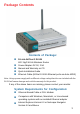
Package Contents Contents of Package: D-Link AirPlus G DI-524 802.11g/2.4GHz Wireless Router Power Adapter-DC 5V, 2.5A Manual and Warranty on CD Quick Installation Guide Ethernet Cable (All the DI-524’s Ethernet ports are Auto-MDIX) Note: Using a power supply with a different voltage rating than the one included with the DI-524 will cause damage and void the warranty for this product. If any of the above items are missing, please contact your reseller.
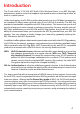
Introduction The D-Link AirPlus G DI-524 802.11g/2.4 Ghz Wireless Router is an 802.11g highperformance, wireless router that supports high-speed wireless networking at home, at work or in public places. Unlike most routers, the DI-524 provides data transfers at up to 54 Mbps (compared to the standard 11 Mbps) when used with other D-Link AirPlus G products. The 802.11g standard is backwards compatible with 802.11b products.
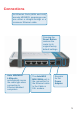
Connections All Ethernet Ports (WAN and LAN) are auto MDI/MDIX, meaning you can use either a straight-through or a crossover Ethernet cable. Pressing the Reset Button restores the router to its original factory default settings. Auto MDI/MDIX LAN ports automatically sense the cable type when connecting to Ethernet-enabled computers. The Auto MDI/ MDIX WAN port is the connection for the Ethernet cable to the Cable or DSL modem. Receptor for the Power Adapter.
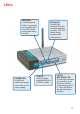
LEDs WAN LED A solid light indicates connection on the WAN port. This LED blinks during data transmission. POWER LED A solid light indicates a proper connection to the power supply. WLAN LED A solid light indicates that the wireless segment is ready. This LED blinks during wireless data transmission. STATUS A blinking light indicates that the DI-524 is ready. LOCAL NETWORK LED A solid light indicates a connection to an Ethernet-enabled computer on ports 14. This LED blinks during data transmission.
Features Fully compatible with the 802.11g standard to provide a wireless data rate of up to 54Mbps. Backwards compatible with the 802.11b standard to provide a wireless data rate of up to 11Mbps. WPA (Wi Fi Protected Access) authorizes and identifies users based on a secret key that changes automatically at a regular interval, for example: TKIP (Temporal Key Integrity Protocol), in conjunction with a RADIUS server, changes the temporal key every 10,000 packets, ensuring greater security.
Wireless Basics D-Link wireless products are based on industry standards to provide easy-to-use and compatible high-speed wireless connectivity within your home, business or public access wireless networks. D-Link wireless products will allow you access to the data you want, when and where you want it. You will be able to enjoy the freedom that wireless networking brings. A WLAN is a cellular computer network that transmits and receives data with radio signals instead of wires.
Wireless Basics (continued) Standards-Based Technology The DI-524 Wireless Broadband Router utilizes the new 802.11g standard. The IEEE 802.11g standard is an extension of the 802.11b standard. It increases the data rate up to 54 Mbps within the 2.4GHz band, utilizing OFDM technology. This means that in most environments, within the specified range of this device, you will be able to transfer large files quickly or even watch a movie in MPEG format over your network without noticeable delays.
Wireless Basics (continued) Installation Considerations The D-Link AirPlus G DI-524 lets you access your network, using a wireless connection, from virtually anywhere within its operating range. Keep in mind, however, that the number, thickness and location of walls, ceilings, or other objects that the wireless signals must pass through, may limit the range. Typical ranges vary depending on the types of materials and background RF (radio frequency) noise in your home or business.
Getting Started Setting up a Wireless Infrastructure Network 1 2 3 4 6 5 Please remember that D-Link AirPlus G wireless devices are pre-configured to connect together, right out of the box, with their default settings. For a typical wireless setup at home (as shown above), please do the following: You will need broadband Internet access (a Cable or DSL-subscriber line into your home or office). Consult with your Cable or DSL provider for proper installation of the modem.
Using the Configuration Menu Whenever you want to configure your network or the DI-524, you can access the Configuration Menu by opening the web-browser and typing in the IP Address of the DI-524. The DI-524 default IP Address is shown at right: Open the web browser Type in the IP Address of the Router (http://192.168.0.1) http://192.168.0.1 Note: if you have changed the default IP Address assigned to the DI-524, make sure to enter the correct IP Address.
Using the Configuration Menu (continued) Home > Wireless SSID- Service Set Identifier (SSID) is the name designated for a specific wireless local area network (WLAN). The SSID’s factory default setting is default. The SSID can be easily changed to connect to an existing wireless network or to establish a new wireless network. Channel- 6 is the default channel. All devices on the network must share the same channel. (Note: The wireless adapters will automatically scan and match the wireless setting.
Using the Configuration Menu (continued) Home > WAN > Dynamic IP Address DI-754 Dynamic IP Address- Choose Dynamic IP Address to obtain IP Address information automatically from your ISP. Select this option if your ISP does not give you any IP numbers to use. This option is commonly used for Cable modem services. Host Name- The Host Name is optional but may be required by some ISPs. The default host name is the device name of the Router and may be changed.
Using the Configuration Menu (continued) Home > WAN > Static IP Address Static IP Address- Choose Static IP Address if all WAN IP information is provided to you by your ISP. You will need to enter in the IP address, subnet mask, gateway address, and DNS address(es) provided to you by your ISP. Each IP address entered in the fields must be in the appropriate IP form, which are four octets separated by a dot (x.x.x.x). The Router will not accept the IP address if it is not in this format.
Using the Configuration Menu (continued) Home > WAN > PPPoE Please be sure to remove any existing PPPoE client software installed on your computers. Choose PPPoE (Point to Point Protocol over Ethernet) if your ISP uses a PPPoE connection. Your ISP will provide you with a username and password. This option is typically used for DSL services. Select Dynamic PPPoE to obtain an IP address automatically for your PPPoE connection. Select Static PPPoE to use a static IP address for your PPPoE connection.
Using the Configuration Menu (continued) Home > WAN > PPPoE continued Maximum Enter a maximum idle time during which Internet connection is maintained during inactivity. To disable this feature, enable AutoIdle Timereconnect. MTU- Maximum Transmission Unit-1492 is the default setting-you may need to change the MTU for optimal performance with your specific ISP.
Using the Configuration Menu (continued) Home > DHCP DHCP stands for Dynamic Host Control Protocol. The DI-524 has a built-in DHCP server. The DHCP Server will automatically assign an IP address to the computers on the LAN/ private network. Be sure to set your computers to be DHCP clients by setting their TCP/ IP settings to “Obtain an IP Address Automatically.” When you turn your computers on, they will automatically load the proper TCP/IP settings provided by the DI-524.
Using the Configuration Menu (continued) Advanced > Virtual Server The DI-524 can be configured as a virtual server so that remote users accessing Web or FTP services via the public IP address can be automatically redirected to local servers in the LAN (Local Area Network). The DI-524 firewall feature filters out unrecognized packets to protect your LAN network so all computers networked with the DI-524 are invisible to the outside world.
Using the Configuration Menu (continued) Advanced > Virtual Server continued Virtual Server- Select Enabled or Disabled. Name- Enter the name referencing the virtual service. Private IP- The server computer in the LAN (Local Area Network) that will be providing the virtual services. Protocol Type- The protocol used for the virtual service. Private Port- The port number of the service used by the Private IP computer.
Using the Configuration Menu (continued) Advanced > Virtual Server continued Click on this icon to edit the virtual service Click on this icon to delete the virtual service Example #2: If you have an FTP server that you wanted Internet users to access by WAN port 2100 and only during the weekends, you would need to enable it as such. FTP server is on LAN computer 192.168.0.30. FTP uses port 21, TCP. Name: FTP Server Private IP: 192.168.0.
Using the Configuration Menu (continued) Advanced > Applications Some applications require multiple connections, such as Internet gaming, video conferencing, Internet telephony and others. These applications have difficulties working through NAT (Network Address Translation). Special Applications makes some of these applications work with the DI-524.
Using the Configuration Menu (continued) Advanced > Filters > IP Filters Filters are used to deny or allow LAN (Local Area Network) computers from accessing the Internet. The DI-524 can be setup to deny internal computers by their IP or MAC addresses. The DI-524 can also block users from accessing restricted web sites. IP Filters- Use IP Filters to deny LAN IP addresses from accessing the Internet. You can deny specific port numbers or all ports for the specific IP address.
Using the Configuration Menu (continued) Advanced > Filters > URL Blocking URL Blocking is used to deny LAN computers from accessing specific web sites by the URL. A URL is a specially formatted text string that defines a location on the Internet. If any part of the URL contains the blocked word, the site will not be accessible and the web page will not display. To use this feature, enter the text string to be blocked and click Apply. The text to be blocked will appear in the list.
Using the Configuration Menu (continued) Advanced > Filters > MAC Filters Use MAC (Media Access Control) Filters to allow or deny LAN (Local Area Network) computers by their MAC addresses from accessing the Network. You can either manually add a MAC address or select the MAC address from the list of clients that are currently connected to the Broadband Router. Filters- Select the filter you wish to use; in this case, MAC filters was chosen.