D-Link AirPlus G+ DI-824VUP High-Speed Enhanced 2.
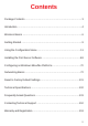
Contents Package Contents................................................................................. 3 Introduction............................................................................................4 Wireless Basics ....................................................................................6 Getting Started ...................................................................................... 9 Using the Configuration Menu..............................................................
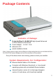
Package Contents Contents of Package: D-Link AirPlus G+ DI-824VUP High-Speed Enhanced 2.4GHz Wireless VPN Router Power Adapter - 5V DC / 2.5A Manual on CD Quick Installation Guide Note: Using a power supply with a different voltage rating than the one included with the DI-824VUP will cause damage and void the warranty for this product. If any of the above items are missing, please contact your reseller.
Introduction The D-Link AirPlus G+ DI-824VUP Wireless Broadband Router is an enhanced 802.11b high-performance, wireless router with a printer port. It is an ideal way to extend the reach and number of computers connected to your wireless network. Unlike most 802.11g routers, the DI-824VUP is capable of data transfer speeds up to 54 Mbps (compared to the standard 11 Mbps) when used with other DLink AirPlus Xtreme G products such as the DWL-G650 and DWL-G520 Wireless Adapters.
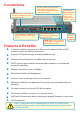
Connections COM port is the connection to another COM port or backup dial-up modem. The LPT port or USB port is used to connect to your local printer. All ports (both LAN and WAN) auto-sense cable types to accomodate straight-through or cross-over cable. Pressing the Reset Button restores the router to its original factory default settings. LAN ports provide connections to Ethernetenabled devices. Features & Benefits WAN port is the connection for the Ethernet cable to the Cable or DSL modem.
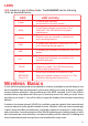
LEDS LED stands for Light-Emitting Diode. The DI-824VUP has the following LEDs as described below: LED LED Activity Power A steady light indicates a connection to a power source WAN A solid light indicates connection on the WAN port.
Wireless Basics Wireless users can use the same applications they use on a wired network. Wireless adapter cards used on laptop and desktop systems support the same protocols as Ethernet adapter cards. Under many circumstances, it may be desirable for mobile network devices to link to a conventional Ethernet LAN in order to use servers, printers, or an Internet connection supplied through the wired LAN. A Wireless Router is a device used to provide this link.
Wireless Basics The DI-824VUP is compatible with other D-Link AirPlus Xtreme G 802.11g products, which include: ♦ Enhanced 2.4GHz Wireless Cardbus Adapters used with laptop computers (DWL-G650) ♦ Enhanced 2.4GHz Wireless PCI cards used with desktop computers (DWL-G520) Standards-Based Technology Based on the IEEE 802.11g standard, the DI-824VUP is interoperable with existing compatible 2.
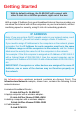
Getting Started With its default settings, the DI-824VUP will connect with other D-Link Air or AirPlus products, right out of the box. With a single IP Address from your Broadband Internet Service provider you can share the Internet with all the computers on your local network, without sacrificing speed or security, using D-Link Air networking products. IP ADDRESS Note: If you are using a DHCP-capable router in your network setup, such as the DI-824VUP, you will not need to assign a static IP Address.
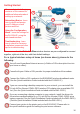
Getting Started Please refer to the following sections of this manual for additional information about setting up a network: Networking Basics - learn how to check and assign your IP Address; share printers and files. 1 2 6 3 4 Using the Configuration Menu - learn the settings for the DI-824VUP, using the web-based interface. Troubleshooting - learn how to check for common installation issues and other tips for troubleshooting.
Using the Configuration Menu Whenever you want to configure your network or the DI-824VUP, you can access the Configuration Menu by opening the web-browser and typing in the IP Address of the DI-824VUP. The DI-824VUP default IP Address is shown below: Open the web browser Type in the IP Address of the DI-824VUP http://192.168.0.1 Note: if you have changed the default IP Address assigned to the DI-824VUP, make sure to enter the correct IP Address.
Using the Configuration Menu Home > Wireless SSID default is the default setting. All devices on the network must share the same SSID. If you change the default setting, the SSID may be up to 32 characters long. Channel WEP 6 is the default channel. All devices on the network must share the same channel. Click Enabled or Disabled (default). WEP Encryption Select the level of encryption desired: 64, 128, or 256-bit.
Using the Configuration Menu Home > Wireless 13
802.1x The 802.1x is an authentication method which is designed to compliment the existing WEP encryption. During the authentication process, the server verifies the identity of the client attempting to connect to the network. With the proper client account and encryption key, access to the network is granted. Unfamiliar encryption key or clients are denied from accessing the wireless network. This feature will help safe guard a Local Area Network (LAN) from unwanted visitors.
Using the Configuration Menu Home > WAN Choose WAN Type WAN stands for Wide Area Network. In this case WAN represents the mode in which your ISP connects to the Internet. If you are uncertain, please ask your ISP which of the following represents your connection mode to the Internet: Dynamic IP Address Obtain an IP address from your ISP automatically (mainly for Cable users). Static IP Address Your ISP assigns you a Static IP Address.
Using the Configuration Menu Home > WAN > Dynamic IP Address Most Cable modem users will select this option to obtain an IP Address automatically from their ISP (Internet Service Provider). Host Name This is optional, but may be required by some ISPs. The host name is the device name of the Router. Renew IP Forever Enable this feature to allow the router to automatically reconnect to the ISP if the connection drops.
Using the Configuration Menu Home > WAN > Static IP Address If you use a Static IP Address, you will input information here that your ISP has provided to you. WAN IP Address Input the IP Address provided by your ISP. WAN Subnet Mask Input the Subnet Mask provided by your ISP. WAN Gateway Input the Gateway address provided by your ISP. Primary DNS Input the primary DNS address provided by your ISP. Secondary DNS (Optional) Input the Secondary DNS address provided by your ISP.
Using the Configuration Menu Home > WAN > PPPoE Most DSL users will select this option to obtain an IP address automatically from their ISP through the use of PPPoE. User Name Your PPPoE username provided by your ISP. Password Your PPPoE password provided by your ISP. Service Name (Optional) Check with your ISP for more information if they require the use of service name. IP Address (Optional) Enter in the IP Address if you are assigned a static PPPoE address.
Using the Configuration Menu Home > WAN > Dial-up Network Most Dial-up users will select this option to connect to their ISP through an analog dial-up modem. This feature can be used as a back-up when your broadband connectivity is unavailable. Dial-up Telephone Telephone number to connect to your ISP Dial-up Account Username provided by your ISP Dial-up Password Password provided by your ISP Primary DNS/ Seconday DNS If the settings are configured as “0.0.0.
Using the Configuration Menu Home > WAN > Others > PPTP Point-to-Point Tunneling Protocol (PPTP) is a WAN connection used in Europe. My IP Address Enter the IP Address. My Subnet Mask Enter the Subnet Mask. Server IP Address Enter the Server IP Address. PPTP Account Enter the PPTP account name. PPTP Password Enter the PPTP password. Connection ID (Optional) Enter the connection ID if required by your ISP.
Using the Configuration Menu Home > WAN > Others > L2TP Layer 2 Tunneling Protocol(L2TP) is a WAN connenction used in Israel. IP Address IP address provided by your ISP. Subnet Mask Subnet mask provided by your ISP. Server IP IP Address of LNS provided by your ISP. L2TP Account Your L2TP username provided by your ISP. L2TP password Your L2TP password provided by your ISP. Retype Password Re-enter L2TP password. Maximum Idle Time Set it to zero or enable Auto-reconnect to disable this feature.
Using the Configuration Menu Home > WAN > Others > BigPond Cable Dynamic IP Address for BigPond is a WAN connection used in Australia. User Name Enter in the user name for the BigPond account. Password Enter the password for the BigPond account. Login Server IP (Optional) Enter the Login Server IP if required. Auto-reconnect If enabled, the Broadband Router will automatically connect to your ISP after your system is restarted or if the connection is dropped.
Using the Configuration Menu Home > LAN LAN is short for Local Area Network. This is considered your internal network. These are the IP settings of the LAN interface for the DI-824VUP. These settings may be referred to as Private settings. You may change the LAN IP address if needed. The LAN IP address is private to your internal network and cannot be seen on the Internet. IP Address The IP address of the LAN interface. The default IP address is: 192.168.0.1.
Using the Configuration Menu Home > DHCP DHCP stands for Dynamic Host Control Protocol. The DI-824VUP has a built-in DHCP server. The DHCP Server will automatically assign an IP address to the computers on the LAN/private network. Be sure to set your computers to be DHCP clients by setting their TCP/IP settings to “Obtain an IP Address Automatically.” When you turn your computers on, they will automatically load the proper TCP/IP settings provided by the DI-824VUP.
Using the Configuration Menu Home > VPN Settings VPN Settings are settings that are used to create virtual private tunnels to remote VPN gateways. The tunnel technology supports data confidentiality, data origin, authentication, and data integrity of network information by utilizing encapsulation protocols, encryption algorithms, and hashing algorithms. VPN Click Enable to enable VPN tunnels. When you are not using the VPN feature, it is best to keep VPN disabled.
Using the Configuration Menu Home > VPN Settings > Tunnel > Method >IKE Tunnel Name Current tunnel name. Aggressive Mode Enabling this mode will accelerate establishing tunnel, but the device will have less security. Local Subnet The subnet of the VPN gateway’s local network. It can be a host, a partial subnet or a whole subnet. Local Netmask Local netmask combined with local subnet to form a subnet domain. Remote Subnet The subnet of the remote VPN gateway’s local network.
Using the Configuration Menu Home > VPN Settings > Tunnel > Method > IKE > Select IKE Proposal IKE Proposal index A list of selected proposal indexes from the IKE proposal pool listed below. Proposal Name This is the name used to classify the IKE proposal. DH Group There are three groups that can be selected: group 1 (MODP768), group 2 (MODP1024), and group 5 (MODP1536). Encrypt algorithm There are two algorithms that can be selected: 3DES and DES.
Using the Configuration Menu Home > VPN Settings > Tunnel > Method > IKE > Select IKE Proposal Continued... Life Time Enter in the life time value. Life Time Unit There are two units that can be selected: second and KB. Proposal ID The identifier of IKE proposal can be chosen for adding the corresponding proposal to the dedicated tunnel. Add to Click it to add the chosen proposal indicated by proposal ID to IKE Proposal index list.
Using the Configuration Menu Home > VPN Settings > Tunnel > Method > IKE > Select IPSEC Proposal IPSec Proposal index A list of selected proposal indexes from the IPSec proposal pool listed below. Proposal Name This is the name used to classify the IPSec Proposal DH Group There are three groups that can be selected: group 1 (MODP768), group 2 (MODP1024), and group 5 (MODP1536). Encap protocol There are two protocols that can be selected: ESP and AH.
Using the Configuration Menu Home > VPN Settings > Tunnel > Method > IKE > Select IPSEC Proposal Continued... Life Time Enter in a life time value. Life Time Unit There are two units that can be selected: second and KB. Proposal ID The identifier of IPSec proposal can be chosen for adding the corresponding proposal to the dedicated tunnel. Add to Click it to add the chosen proposal indicated by proposal ID to IPSec Proposal index list.
Using the Configuration Menu Home > VPN Settings > Tunnel > Manual Tunnel Name Current tunnel name. Aggressive Mode Enabling this mode will accelerate establishing tunnel, but the device will have less security. Local Subnet The subnet of the VPN gateway’s local network. It can be a host, a partial subnet, or a whole subnet. Local Netmask Local netmask combined with local subnet to form a subnet domain. Remote Subnet The subnet of the remote VPN gateway’s local network.
Using the Configuration Menu Home > VPN Settings > Tunnel > Manual Continued... Encapsulation Protocol There are two protocols that can be selected: ESP and AH. Encryption Algorithm There are two algorithms that can be selected: 3DES and DES. Encryption Key For DES, the encryption key is 8 bytes (16 Char.). For 3DES, the encryption key is 24 bytes (48 Char.). Authentication Algorithm There are two algorithms that can be selected: SHA1 and MD5.
Using the Configuration Menu Home > VPN Settings > Dynamic VPN Tunnel VPN Settings - IKE There are three parts that are necessary to setup the configuration of IKE for the dedicated tunnel: basic setup, IKE proposal setup, and IPSec proposal setup. Basic setup includes the setting of following items: local subnet, local netmask, remote subnet, remote netmask, remote gateway, and pre-shared key. The tunnel name is derived from the previous page of VPN setting.
Using the Configuration Menu Home > VPN Settings > Dynamic VPN Tunnel Continued... Preshared Key The first key that supports IKE mechanism of both VPN gateways for negotiating further security keys. The preshared key must be the same for both endpoint gateways. IKE Proposal index Click the button to setup a set of frequent-used IKE proposals and select from the set of IKE proposals for the dedicated tunnel.
Using the Configuration Menu Home > VPN Settings > Dynamic VPN Tunnel > Set IKE Proposal IKE Proposal index A list of selected proposal indexes from the IKE proposal pool listed below. Proposal Name It indicates which IKE proposal to be focused. DH Group There are three groups that can be selected: group 1 (MODP768), group 2 (MODP1024), and group 5 (MODP1536). Encrypt algorithm There are two algorithms that can be selected: 3DES and DES.
Using the Configuration Menu Home > VPN Settings > Dynamic VPN Tunnel > Set IKE Proposal Continued... Life Time Enter in the life time value. Life Time Unit There are two units that can be selected: second and KB. Proposal ID The identifier of IKE proposal can be chosen for adding the corresponding proposal to the dedicated tunnel. Add to Click it to add the chosen proposal indicated by proposal ID to IKE Proposal index list.
Using the Configuration Menu Home > VPN Settings > Dynamic VPN Tunnel > Set IPSEC Proposal IPSec Proposal index A list of selected proposal indexes from the IPSec proposal pool listed below. Proposal Name This is the name used to classify the IPSec proposal. DH Group There are three groups that can be selected: group 1 (MODP768), group 2 (MODP1024), and group 5 (MODP1536). Encap protocol There are two protocols that can be selected: ESP and AH.
Using the Configuration Menu Home > VPN Settings > Dynamic VPN Tunnel > Set IPSEC Proposal Continued... Life Time Enter in a life time value. Life Time Unit There are two units that can be selected: second and KB. Proposal ID The identifier of IPSec proposal can be chosen for adding the corresponding proposal to the dedicated tunnel. Add to Click it to add the chosen proposal indicated by proposal ID to IPSec Proposal index list.
Using the Configuration Menu Home > VPN Settings > L2TP Server Setting Enable L2TP Server Click to enable the L2TP Server function. Virtual IP of L2TP Server Enter your Virtual IP address to access the L2PT server. Authentication Protocol Select one of the following authentication protocols: PAP, CHAP, or MSCHAP. Tunnel Name Current tunnel name. User Name Enter in the username for the L2TP account. Password Enter in the password for the L2TP account.
Using the Configuration Menu Home > VPN Settings > PPTP Server Setting Enable PPTP Server Click to enable the PPTP Server function. Virtual IP of PPTP Server Enter your Virtual IP address to access thePPPT server. Authentication Protocol Select one of the following authentication protocols: PAP, CHAP, or MSCHAP. Tunnel Name Current tunnel name. User Name Enter in the username for the PPTP account. Password Enter in the password for the PPTP account.
Using the Configuration Menu Advanced > Virtual Server The DI-824VUP can be configured as a virtual server so that remote users accessing Web or FTP services via the public IP address can be automatically redirected to local servers in the LAN (Local Area Network). The DI-824VUP firewall feature filters out unrecognized packets to protect your LAN network so all computers networked with the DI-824VUP are invisible to the outside world.
Using the Configuration Menu Advanced > Application Some applications require multiple connections, such as Internet gaming, video conferencing, Internet telephony, and others. These applications have difficulties working through NAT (Network Address Translation). Special Applications makes some of these applications work with the DI-824VUP.
Using the Configuration Menu Advanced > Filter > IP Filter Use IP (Internet Protocol) filters to allow or deny computers access to the Internet based on their IP address. IP Filter Use IP Filters to deny LAN IP addresses access to the internet. Enabled or Disabled Click Enabled to apply the filter policy or click Disabled to enter an inactive filter policy. (You can reactivate the policy later.) IP Address Enter in the IP address range of the computers that you want the policy to apply to.
Using the Configuration Menu Advanced > Filter > MAC Filters MAC (Media Access Control) Filters are used to allow or deny LAN (Local Area Network) computers from accessing the Internet and network by their MAC address. At the bottom of the screen, there is a list of MAC addresses from the DHCP client computers connected to the DI-824VUP. To use them, select one from the drop down list. Then click the “Apply” button and the DI-824VUP will fill in the appropriate information to the list.
Using the Configuration Menu Advanced > Filter > URL Blocking Use URL Blocking to deny LAN computers from accessing specific web sites by its URL. A URL is a specially formatted text string that defines a location on the Internet. If any part of the URL contains the blocked word, the site will not be accessible and the web page will not display. Disabled URL Blocking Select this option if you do not want to use URL Blocking.
Using the Configuration Menu Advanced > Filter > Domain Blocking Use Domain Blocking to allow or deny computers access to specific Internet domains whether it is through www, ftp, snmp, etc. Disabled Domain Blocking Select this option if you do not want to use Domain Blocking. Allow users to access all domains except “Blocked Domains” Select this option to allow users to access the specified Internet domains listed below. Users will be denied access to all other Internet domains.
Using the Configuration Menu Advanced > Firewall Firewall Rules is an advance feature used to allow or deny traffic from passing through the device. It works in the same way as IP Filters with additional settings. You can create more detailed rules for the device. Enabled or Disabled Click Enabled to apply the filter policy or click Disabled to enter an inactive filter policy (You can reactivate the policy later). Name Enter the name of the Firewall Rule.
Using the Configuration Menu Advanced > Firewall Continued IP Address Enter in the IP address range of the computers that you want the policy to apply to. If it is only a single computer that you want the policy applied to, then enter the IP address of that computer in the Start Source IP and leave the End Source IP blank. Protocol Select one of the following protocols: TCP, UDP, or ICMP. Port Range Enter in the port range of the TCP/UDP ports that you want the policy to apply to.
Using the Configuration Menu Advanced > SNMP SNMP (Simple Network Management Protocol) is a widely used network monitoring and control protocol that reports activity on each network device to the administrator of the network. SNMP can be used to monitor traffic and statistics of the DI-824VUP. The DI824VUP supports SNMP v1 or v2c. Enable SNMP (Simple Network Management Protocol.) Local LAN (Local Area Network). Remote WAN (Wide Area Network).
Using the Configuration Menu Advanced > DDNS DDNS (Dynamic Domain Name System) keeps dynamic IP addresses (e.g., IP addresses assigned by a DHCP capable router or server) linked to a domain name. Users who have a Dynamic DNS account may use this feature on the DI-824VUP. DDNS When an IP address is automatically assigned by a DHCP server, DDNS automatically updates the DNS server. Select Disabled or Enabled. Provider Select from the pull-down menu. Host Name Enter the Host name.
Using the Configuration Menu Advanced > Routing Static routes can be added if you require specific routes within your internal network. These routes will not apply to the WAN (Internet) network. Dynamic Routing Dynamic Routing Settings allow the VPN Router to route IP packets to another network automatically. The RIP protocol is applied, and broadcasts the routing information to other routers on the network regularly. By default, it is set to disable. Check to enable (RIPv1 / RIPv2) protocol.
Using the Configuration Menu Advanced > DMZ If you have a computer that cannot run Internet applications properly from behind the DI824VUP, then you can allow that computer to have unrestricted Internet access. Enter the IP address of that computer as a DMZ (Demilitarized Zone) host with unrestricted Internet access. Adding a client to the DMZ may expose that computer to a variety of security risks; so only use this option as a last resort.
Using the Configuration Menu Advanced > Performance Beacon Interval Beacons are packets sent by an Access Point to synchronize a wireless network. Specify a value. 100 is the default setting and is recommended. DTIM interval (Delivery Traffic Indication Message) 3 is the default setting. A DTIM is a countdown informing clients of the next window for listening to broadcast and multicast messages. TX Rates Select the data rate. Default is 1-2-5.5-11-22-54Mbps.
Using the Configuration Menu Advanced > Performance (Continued) Authentication Open System Shared Key Both Select Open system, Shared Key or Both. The DI-824VUP will be visible to all devices on the network. This is the default setting. In this mode, in order to access the DI-824VUP on the network, the device must be listed in the MAC Address Control List. In this mode, all devices on the network can access the DI-824VUP. SSID Broadcast Enable is the default setting.
Using the Configuration Menu Tools > Admin You can change the administrator and user passwords here. It is recommended that you change the administrator password from the default setting.The default password is blank (nothing). Password To change the administrator or user password, enter in the old password and enter the new password twice to confirm. Remote Management Remote Management allows the device to be configured through the WAN (Wide Area Network) port from the Internet using a web browser.
Using the Configuration Menu Tools > Time You will need to set the time zone corresponding to your location. The time can be set manually or the device can connect to a NTP (Network Time Protocol) server to retrieve the time. Enable NTP (Network Time Protocol). Select to synchronize the time on the DI-824VUP to an NTP server. Set Device Date and Time You can manually set the time on your network here.
Using the Configuration Menu Tools > System The current system settings can be saved as a file onto the local hard drive. The saved file or any other saved setting file created by the DI-824VUP can be uploaded into the unit. To reload a system settings file, click on “Browse” to search the local hard drive for the file to be used. The device can also be reset back to factory default settings by clicking on “Reset to Default” button. Use the restore feature only if necessary.
Using the Configuration Menu Tools > Firmware You can upgrade the firmware of the device using this tool. Make sure that the firmware you want to use is saved on the local hard drive of the computer. Click on “Browse” to search the local hard drive for the firmware to be used for the update. Upgrading the firmware will not change any of your system settings but it is recommended that you save your system settings before doing a firmware upgrade.
Using the Configuration Menu Tools > Misc Ping Test In the open box, enter in a URL (i.e., www.dlink.com) or an IP address and click on Ping to test your internet connection. Restart Device Click Reboot to restart the unit. Block WAN Ping Click Enable to block the WAN ping. Computers on the Internet will not get a reply back from the DI-824VUP when it is being “ping”ed. This may help to increase security.
Using the Configuration Menu Tools > Misc (Continued) UPnP UPnP is short for Universal Plug and Play which is a networking architecture that provides compatibility among networking equipment, software, and peripherals. The DI-824VUP is a UPnP enabled router and will only work with other UPnP devices/softwares. If you do not want to use the UPnP Functionality, it can be disabled by selecting “Disabled”.
Using the Configuration Menu Status > Device Info This screen displays information about the DI-824VUP such as WAN, LAN, and Wireless status. DHCP Renew Use this button to reconnect to your ISP, if your WAN connection is set up for DHCP. DHCP Release Use this button to disconnect from your ISP, if your WAN connection is set up for DHCP.
Using the Configuration Menu Status > Log This screen displays activities occurring on the DI-824VUP. First Page Click First Page to go to the first page of the log. Last Page Click Last Page to go to the last page of the log. Previous Click Previous to go to the previous page of the log. Next Click Next to go to the next page of the log. Clear Click Clear to clear the current page of the log. Log Settings Click for advanced features (see next page).
Using the Configuration Menu Status > Log > Log Settings E-Mail Alert The DI-824VUP can be set up to send the log files to a specific email address. SMTP Server IP Enter in the IP address of the mail server. Email Address Enter in the email address of the recipient who will receive the email log. Send Mail Now Click to send mail immediately. IP Address of the Syslog Server Enter in the IP address of a syslog server within the network. Click Enable to activate the policy.
Using the Configuration Menu Status > Stats In the Stats section, traffic statistics are displayed. Refresh This will update the page. Reset This will reset the packet counter to zero. WAN Displays Received / Transmitted packets from the WAN port. LAN Displays Received / Transmitted packets from the LAN port.
Using the Configuration Menu Status > Wireless This screen displays the connection time and the MAC Address of the connected wireless clients. Click on Refresh for the most recent information.
Using the Configuration Menu Status > Wireless This screen displays the VPN connection state. Click on Refresh for the most recent information.
Using the Configuration Menu Help This screen displays the complete Help menu. For help at anytime, click the Help tab in the Configuration menu.
Installing the Print Server Software Insert the installation CD-ROM into the CD-ROM drive. The following window will be shown automatically. If it is not, please run “autorun.exe” on the CD-ROM.
Installing the Print Server Software (continued) Wait until the following Welcome dialog appears. Click Next Select the destination folder. Click Next Then, the setup program will begin to install the programs into the destination folder. When the following window is displayed. Click Finish After rebooting your computer, the software installation procedure is finished.
Configuring on Windows 98se/Me Platforms After you finish the software installation procedure, your computer will be capable of network printing provided by the DI824VUP. For convenience, we call the printer connected to the printer port of the DI-824VUP a printer server. On a Windows 95/98 platform, open the Printers window in the My Computer menu. Now, you can configure the print server of the DI-824VUP: Find out the corresponding icon of your printer server, for example, the HP LaserJet 6L.
Configuring on Windows 2000/XP Platforms Click Port The configuration procedure for a Windows 2000/XP platform is similar to that of Windows 95/98 except the screen of printer Properties. Click Configure Port Choose your printer interface. Type in the IP address of the DI-824VUP. Click OK (Note: Screen shots are taken in Windows 2000, similar screens will appear in Windows XP.
Networking Basics Using the Network Setup Wizard in Windows XP In this section you will learn how to establish a network at home or work, using Microsoft Windows XP. Note: Please refer to websites such as http://www.homenethelp.com and http://www.microsoft.com/windows2000 for information about networking computers using Windows 2000, ME or 98. Go to Start > Control Panel > Network Connections Select Set up a home or small office network When this screen appears, Click Next.
Networking Basics Please follow all the instructions in this window: Click Next. In the following window, select the best description of your computer. If your computer connects to the internet through a gateway/router, select the second option as shown. Click Next.
Networking Basics Enter a Computer description and a Computer name (optional). Click Next. Enter a Workgroup name. All computers on your network should have the same Workgroup name. Click Next.
Networking Basics Please wait while the Network Setup Wizard applies the changes. When the changes are complete, click Next. Please wait while the Network Setup Wizard configures the computer. This may take a few minutes.