DRO-210i Broadband Business Gateway User Guide (Updated for Firmware Revision 2.1.2) D-Link India Ltd., Software and R&D Center, Bangalore. Phone: 91-80-26788345/46/50/51 www.dlink.co.
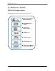
Table Of Contents ABOUT THIS MANUAL .............................................................................. 4 1 PRODUCT OVERVIEW ............................................................................ 5 1.1 HARDWARE DETAILS ................................................................................................. 6 1.2 SOFTWARE FEATURES ............................................................................................... 9 2 INTERFACES ..........................................
7.1.1 Interface Configuration.............................................................................................................. 36 7.1.2 Policy Rules ............................................................................................................................... 37 7.1.3 Inbound Policies ........................................................................................................................ 38 7.1.4 Outbound Policies.................................................
About This Manual This document provides information related to the installation and configuration of DRO210i along with a description of all its features. This document is intended for service providers and network administrators who guide the network infrastructure deployment in enterprises. Note: Copyright to this manual is owned by D-Link India Ltd. This document shall not be reproduced, distributed or copied without the permission from D-Link India Ltd.
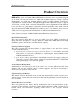
Product Overview 1 Product Overview DRO-210i is a part of D-Link's DRO-2XX Business Gateway series, especially designed as an all-in-one network solution for small and medium businesses. Today's network infrastructure for small and medium business calls for highly reliable connectivity, comprehensive security features and high throughput with sophisticated QoS to support Voice/Video over IP.
Product Overview 1.
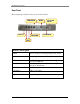
Product Overview Front Panel The front panel provides the LEDs to indicate the status of the router.
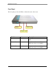
Product Overview Rear Panel The rear panel provides the router’s ports and reset button.
Product Overview 1.2 Software Features The router has rich features like routing, load-balancing, auto backup, firewall access control, secure VPN connectivity, network address translation, quality of service and remote management satisfying most of the needs of the SMB market. Routing The router supports static, dynamic and policy-based routing. Static Routing - The network administrator can manually configure the routes according to his network topology.
Product Overview Network Address Translation (NAT) NAT enables the router to act as an address translation agent between the Internet (public network) and the local (or private) network. The router supports all the combinations of NAT models like Many to Many, Many to One and One to One to provide internet access to LAN client. And the Virtual Server (or Port Forwarding) feature enables remote access to the Company Servers (HTTP/FTP etc) from WAN.
Product Overview Tools The router supports various tools to manage and monitor the device. Syslog - The Router can send the Syslog messages to the configured server to aid in network administration. NTP - The administrator can configure the system date and time manually. Or he can use NTP feature to automatically synchronize the router’s time with specified global time servers.
Interfaces 2 Interfaces The router provides the following interface ports: LAN Ports - The router has two dedicated 10/100 Ethernet LAN ports. DMZ Port - The router has one 10/100 Ethernet DMZ port. A DMZ port is used to connect to the company servers (e.g. Web server, FTP Server). This port can be optionally reconfigured as a regular LAN port. WAN Ports - The router has two 10/100 Ethernet WAN ports. One WAN port can be optionally reconfigured to operate as LAN Port.
Interfaces Port 4 is reconfigured as LAN, the entries configured on WAN2/DMZ earlier will be displayed in dark grey color in the corresponding feature tables to indicate that these entries are currently invalid. Note: When Port 4 is configured as LAN, Load Balancing and Auto Backup features get disabled as there is only one WAN interface available. 2.2 LAN Interface The user systems can be connected to the LAN Interface.
Interfaces Select Interface → DMZ to configure DMZ Settings as explained below. DMZ Settings Web UI IP Address Enter the IP address of the DMZ interface Subnet Mask Enter the subnet mask of the DMZ interface To add a DMZ Server in the network, the administrator can a) Assign Private IP Addresses to the DMZ network. And configure a One-To-One NAT entry to map a Global IP Address to the Private DMZ Server IP Address. Refer NAT Configuration for more details.
Interfaces 2.4.1 Static Mode In this mode, the ISP allocates and provides a static Global IP Address for WAN connectivity. The ISP will also provide information regarding the Default Gateway IP Address to be used for this connection. If you have purchased multiple static Global IP Addresses from the ISP, then configure the first IP Address as the WAN Interface IP Address. And use the rest of your static IP Addresses for Many-To-Many or One-To-One NAT Configuration.
Interfaces After entering all the information press the Apply button. The DHCP Client Status table will now show the DHCP client status at the bottom of the page. Click on Detect Link Status to configure the Ethernet WAN Link Detection Feature. 2.4.3 PPPoE Mode In this mode, ISP provides the Global IP address automatically using PPPoE Protocol. PPPoE protocol is a method of transmitting PPP packets over Ethernet network. Hence PPPoE is an acronym for PPP over Ethernet.
Interfaces PPPoE Settings for WAN1 Interface Web UI Unnumber Interface Select the option to enable unnumbered mode. When this option is not selected the router obtains an IP address from the ISP for the PPPoE connection. Ensure that both ends of the PPPoE link are configured as unnumbered. IP Address Enter the local IP address for the PPPoE connection when Unnumbered mode is enabled. An unnumbered interface borrows the LAN IP address by default.
DHCP, DNS and Time 3 DHCP, DNS and Time 3.1 DHCP DHCP (Dynamic Host Configuration Protocol) is a method of automatically assigning IP address, subnet mask, default gateway and DNS server IP address to hosts on the LAN. This router provides an in-built DHCP Server. In addition, a DHCP Relay is available to relay the DHCP Requests to a DHCP Server on another port. 3.1.1 DHCP Server The DHCP server assigns and manages IP addresses from a specified address pool to DHCP clients.
DHCP, DNS and Time Default Gateway Enter the default gateway IP address that the router will assign to the hosts on the network. Lease Time (sec) Enter the length of time any host on the network can keep its DHCP settings assigned by the router. If the lease expires while the host is logged on, then that host will request for a new set of DHCP settings. The default Lease Time is 60 seconds. Auto Configuration Select Enable to enable the DNS Proxy in the router (the router acts as a DNS server).
DHCP, DNS and Time IP Address Enter the IP address to be assigned to the system with the above MAC Address. After entering all the information press the Apply button. The entries will now be displayed under the DHCP Static Mapping Client Table. If the Static IP in the DHCP Reservation entry does not fall within the DHCP Server IP Range, then it will be treated as an invalid entry. These invalid entries will be displayed in dark grey color in the DHCP Static Mapping Client Table. 3.1.
DHCP, DNS and Time Note: In Relay mode, the DHCP server may unicast the DHCP ACK message to the DHCP Client. So proper routes should be configured at the server to enable it to reach the DHCP Client subnet. 3.2 DNS Proxy DNS (Domain Name System) is the protocol used to translate Domain Names to IP Addresses. DNS is an essential component of internet use, since it allows you to attach easy-to-remember domain names (such as www.dlink.com) to hard-to-remember IP Addresses.
DHCP, DNS and Time 3.3 Time The system date and time of the router can be configured via this option. The system date and time can be configured manually, or it can be obtained automatically from a global time server using NTP. NTP is designed to synchronize the time on a network of machines. NTP runs over the User Datagram Protocol (UDP), using port 123 as both the source and destination port. NTP Version 3 RFC 1305 is used to synchronize timekeeping among a set of distributed time servers and clients.
Routing 4 Routing Routing determines how to transport packets from the initiating host to the receiving host. The packet needs to determine a path through which it can travel from the sender to the receiver. The Routing Table in a router provides such a map to all packets.
Routing 4.1 Static Routing When Static Routing is selected as the routing algorithm, the network administrator needs to manually configure all routes on the router. Any change in the network configuration would require the administrator to update the information in all affected routers. This can be a cumbersome task and lead to errors in case of large and complicated networks. Hence Static routing is typically used for very small networks.
Routing other network configuration problems like routing loop. In the Internet, there are two types of dynamic routing algorithms used – Distance vector and Link State algorithm. In the Distance Vector (DV) algorithm, each router computes the costs of its own attached links and shares the route information with its neighbor routers. The router gradually learns the least-cost path by iterative computation and knowledge exchange with its neighbors.
Routing 4.3 Routing Table The router maintains all the active route entries, and displays them in the Routing table. The static routes configured manually by the administrator are displayed in grey color. And the dynamic routes learnt via RIP are displayed in yellow color. Select Status → Route Table to view the Routing Table as explained below. Web UI Routing Table Destination IP address The destination network reachable through this route. Subnet Mask The subnet mask for this route.
Routing Outbound Interface The network traffic which matches with all the below policy parameters will be sent out of this interface. Policy Parameters Inbound Interface Select the interface through which the incoming traffic will come in. Source Select the source IP address of the traffic. Select Any when there is no specific source IP address. However if Specific is selected the administrator will be allowed to configure specific source IP address for this policy.
High Availability 5 High Availability The High Availability support in the router is an ideal solution for businesses requiring uninterrupted, low cost internet connectivity. The router supports Dual Ethernet WAN Ports for xDSL connectivity. Though xDSL connectivity is cheap, it is more susceptible to outages. Hence with two xDSL links, DRO-210i guarantees uninterrupted internet connectivity. High Availability is made possible through two key features in the router - Auto Backup and Load Balancing. 5.
High Availability 5.2 Load Balancing With multiple Internet connections, Load Balancing effectively uses the combined bandwidth of all the internet links resulting in a significant increase in the total available bandwidth. Also if any Internet connection goes down, uninterrupted internet connectivity is assured utilizing the serviceable links. Based on the speed of the WAN link, the administrator can configure an appropriate percentage of internet traffic to be routed through each of the WAN Links.
High Availability Select Interface → WAN1 and choose IP Setting Mode as Static or Dynamic. Click on Detect Link Status to configure the Ethernet WAN Link Detection as explained below. Web UI Ethernet WAN Link Detection Interface The WAN interface on which link detection is to be performed. Link Detection Select to enable Link Detection on this Interface. Mode Select protocol (ARP or ICMP) used to detect reachability of the default gateway IP address.
Network Address Translation 6 Network Address Translation When a computer wants to connect to the Internet, it needs a legal and unique Global IP address to traverse the internet. With the explosion of Internet, the unique IP address space available is insufficient. NAT solves this problem by allocating single or a small range of legal Global IP addresses. A NAT router translates the unregistered local (or Private) IP addresses to the registered global (or Public) Internet IP addresses.
Network Address Translation 6.1.2 NAT Configuration This router supports the following types of NAT: Many-To-One - In this case, multiple private IP addresses are mapped to one Global IP address by using different ports. Many-To-Many - In this case, multiple private IP addresses are mapped to a pool of Global IP addresses. One-To-One - In this case, one private IP address is mapped to one global IP address. This type of NAT is used to enable internal servers (e.g.
Network Address Translation Consider a scenario where WAN1 is used for internet connectivity. NAT must be enabled at WAN1 to enable LAN systems to access the internet. The company’s servers (Web/FTP Server) may be installed at the DMZ interface using public IP Address for direct access from the internet. NAT should not affect the traffic between DMZ and WAN1, because DMZ systems are already using public/global IP Addresses. In this case, NAT can be disabled between DMZ and WAN1.
Network Address Translation Protocol Select the appropriate application from the list. This selection is equivalent to entering a correct transport type (TCP or UDP) and port number for an application. For example, when SMTP is chosen transport type TCP and port number 25 is automatically entered. Private Settings IP address Enter the private IP address of the server that will provide the service to remote users. Port Enter the private port number on which the server is running.
Network Address Translation 6.4 NAT Table The router maintains a table of sessions for which IP Address and Port Translations have been performed. This translation table can be viewed from the NAT Table Page. Select Status → NAT Table to view the NAT Session Table explained below. Web UI NAT Session Table Private IP address: Port This is the IP address and port number of a host on the private LAN that has an active NAT session.
Firewall 7 Firewall Firewall is a set of security rules that prevents intruders from gaining access to confidential and sensitive information. Its task is to ensure that only approved communication happens and unauthorized communication is blocked and logged. The primary purpose of a firewall is to enforce a security policy stating who can communicate, with whom and in what way.
Firewall Note: If more than one interface is of same security type, then Policy database for them is same i.e if WAN1 and WAN2 are configured as UnTrusted then both of them will share a common Inbound Policies database. Caution: If LAN is configured as UnTrusted, then Remote Access needs to be configured for getting the web-configuration. So before configuring LAN as UnTrusted, first enter the IP of the LAN PC (which is configuring the DRO-210i) in the Remote access configuration webpage. 7.1.
Firewall Note: When an active policy is disabled or deleted, another enabled policy will become active. In this case, currently ongoing sessions will no longer function if they are not permitted by the new active policy. 7.1.3 Inbound Policies The traffic flowing from UnTrusted to Trusted network is the Inbound traffic. By default, all network traffic going from UnTrusted network to Trusted network are blocked. Port Filter rules can be added to allow specific traffic.
Firewall Protocol Select from this drop-down menu the application. This is the equivalent of entering the correct Transport Type and the port number corresponding to a given application. Port Range Enter the range of port numbers for which the current policy rules will be applied. If you have only one port number to enter, enter it in both fields. Direction This is the direction (Inbound) of network traffic for which the current policy entry will be applied.
Firewall Select Firewall → Policy to get to the Policy Table and click Out button to configure Outbound Policies. Web UI Outbound Policies Port Filter Enabled Select Enable to activate Outbound Port Filter. Port Filter is used to deny network packets coming from the trusted domain. Configured outbound port filters will not take effect if this field is disabled. Allow all WAN service to be accessed except “Blocked Service” Click on “Blocked Service” to configure the port filter rules.
Firewall Blocked Services Click on the link “Blocked Services” to get to Blocked Services configuration page. This page allows administrator to specify the application to be blocked from Trusted network to the UnTrusted network. Web UI Outbound Policies (Service Blocked Rule) Add Service Rules Transport Type Select from the drop-down menu a transport type to be blocked by the router. Protocol Select from this drop-down menu the application.
Firewall After entering all the information press the Apply button and the Blocked IP Table will now be displayed at the bottom of the page. Press View button for viewing and Delete button for deleting the corresponding entry. 7.1.5 Domain Filter Domain Filter feature enables the administrator to block specific domain names (or) allow only specific domain names. This feature prevents DNS resolution for the blocked domain names.
Firewall After entering all the information press the Apply button and the status table will now be displayed at the bottom of the page. Press View button for viewing and Delete button for deleting the corresponding entry. 7.1.6 Web Filter The different types of Web Filters in the firewall are Java Filter Cookie Filter ActiveX Filter Keyword Filter File extension Filter Java Filter Java at runtime could allow the attacker to run harmful code on the victim’s computer.
Firewall Keyword Filter HTTP Packets with specific keywords (like jobs) in the URL can be blocked using the Keyword Filter. In Outbound Policies select Keyword List (under Web Filter) to go to the Keyword Filter configuration page. Web UI Enter the Keyword Keyword Filter Enter the keywords to be matched. After entering all the information press the Apply button and the status table will now be displayed at the bottom of the page. Press Delete button for deleting the corresponding entry.
Firewall After entering all the information press the Apply button and the status table will now be displayed at the bottom of the page. Press Delete button for deleting the corresponding entry. 7.1.7 MAC Filter MAC Filter feature can be used to block all traffic from a specific user’s system. The user’s system can be uniquely identified by its MAC Address. In Outbound Policies, select Blocked MAC (under MAC Filter) to go to the Blocked MAC Address configuration page.
Firewall 7.2 Intrusion Detection An Intrusion is a deliberate, unauthorized attempt to access or manipulate information or system and to render them unreliable or unusable. The security architecture that detects and prevents these types of intrusion is called Intrusion Detection and Prevention System. Intrusion Detection Systems (IDS) detect unwanted access to devices on the private network mainly from the public Internet.
Firewall Select Firewall → IDS Configuration to configure the IDS Configuration as explained below. IDS Configuration Web UI Enable IDS Select Enable to activate the IDS. Flood Attack Select Enable to activate all types of flood attacks available on this router i.e. SYN flood attack, ICMP flood attack, ICMP Echo storm attack. In these attacks, packets are flooded continuously on the target machine. Ping of Death Select Enable to activate a form of DoS (denial of service) attack.
Firewall 7.2.2 Intrusion Log When traffic matches an Intrusion signature and is blocked by the IDS engine, the blocking event is recorded in the Intrusion Detection Log. Select Status → Log Tables → Intrusion Log to view the Intrusion Log Table as explained below. Web UI Intrusion Log Table Intrusion Time Displays the time when the intrusion happened. Intrusion Type Displays a brief statement of the type of intrusion that was attempted.
Virtual Private Network 8 Virtual Private Network VPN or virtual private networks allow multiple sites from an organization (and its clients, suppliers, etc.) to communicate securely over an insecure internet by encrypting all communication between the sites. IPSec protocol is the Internet standard protocol for tunneling, encryption and authentication. IPSec can be used to protect the path between a pair of security gateways (Peer-To-Peer Mode) or between a security gateway and a host (IPSec Server Mode).
Virtual Private Network 8.1 IPSec Tunnel or Passthrough The IPSec VPN Feature can operate in 2 modes: IPSec Passthrough: In this mode, the router will allow IPSec-VPN tunnels to be established between multiple LAN side IPSec clients and multiple remote IPSec servers. It can also support multiple LAN side IPSec clients to connect simultaneously to a single remote IPSec server. But the administrator cannot establish tunnels from the router to remote IPSec peers.
Virtual Private Network Add/Modify Tunnel Tunnel ID Enter the alphanumeric string that identifies the remote tunnel. Tunnel Source Interface Select the WAN interface, which serves as the tunnel's source endpoint. Termination Type Select the termination type (Domain name or IP address), which a remote endpoint can use. Termination IP/Name Enter the remote gateway's IP address or domain name depending on the termination type selected.
Virtual Private Network that of DES key and hence it is more secure. User must select exactly the same IKE Encryption algorithm on both ends of a VPN tunnel. Phase 2 Proposal PFS Mode Select the mode that will be used for IPSec Perfect Forward Secrecy (PFS). (Group 1, Group 2, Disabled). • Group 1 uses 768-bit prime number • Group 2 uses 1024-bit prime number • Disable disables the PFS mode. User must use exactly the same PFS mode on both ends of the VPN tunnel.
Virtual Private Network as 192.168.20.0 with subnet mask 255.255.255.0 and outgoing device same as that of the source interface which was specified in the corresponding tunnel entry. 8.3 IPSec Server IPSec server allows tele-workers to connect to their corporate office securely from anywhere in the world. Since the remote user’s IP Address will vary based on the user’s current location, the IPSec server tunnel ignores the client's address.
Virtual Private Network maximum life duration is 86400 seconds. IKE Hash Select the Hash algorithm that will be used to ensure that the messages exchanged between the two IPSec VPN tunnel endpoints has been received exactly as it was sent. In other words, a Hash algorithm is used to generate a binary number by a mathematical operation using the entire message. The resulting number is called a message digest.
Virtual Private Network ESP authentication algorithm on both ends of a VPN tunnel. AH Transform Select the AH authentication algorithm (MD5, SHA) to be used when AH is selected for the IPSec Operation. The user needs to use the same AH authentication method on both ends of a VPN tunnel. A Remote ID needs to exist for each remote user client that wants to connect to the IPSec Server at the router.
Virtual Private Network Tunnel Name This is the name of the tunnel if it is a peer-to-peer configuration or it is the name of the IPSec server if it’s an IPSec server configuration. Termination IP/Domain Name If this is a peer-to-peer tunnel, then it indicates remote peer IP address or its domain name. If it is a IPSec server then "ROAMING MODE" will be displayed. No of Remote IDs This indicates the number of Remote IDs corresponding to the IPSec server.
Virtual Private Network 8.6 IPSec Log The router maintains a log of the IPSec protocol activities i.e Tunnel Negotiation, Establishment and Renegotiation. Select Status → Log Tables → IPSec Log to view the IPSec Log Table as explained below. Web UI IPSec Log Table Index Displays the sequence of the IPSec log. Description Displays a brief description of the log entry, which can be used to check tunnel behavior.
Quality of Service 9 Quality of Service Traffic control in a network can be achieved by Quality of Service (QoS) algorithms, which involves guiding the packets based on some predefined rules. Traffic control classifies packets and places them in individual flows or classes. It can then police by limiting the number of packets transmitted and/or schedule the packets in different order of priority for transmission.
Quality of Service Interface Bandwidth Enter the upstream bandwidth of the interface. Default Class ID Enter the default Class ID for the root class. Corresponding class needs to be added in the class configuration The unclassified traffic will be sent to the class with this default class ID. Root ID The Root ID (configured automatically by the device when we add a root class) is displayed. This is the parent class ID of the interface. Select QoS → HTB Configuration to enter the HTB QoS Configuration.
Quality of Service 9.1.2 Filter Configuration Filters in QoS help in classification of traffic, and assigning the traffic to a specific HTB class. These filters use IP parameters like Source IP, Destination IP, Protocol, Source Port and Destination Port. The packets that match a filter configuration is placed in the class specified with the Class ID parameter and will receive the specified traffic treatment. Multiple filters can be configured for the same Class ID.
Quality of Service After entering all the information press the Apply button and the QoS Filter Entries table will now be displayed at the bottom of the page. Press View button for editing and Delete button for deleting the corresponding entry. Note: 1) Always configure filters to direct traffic to a leaf class (i.e class which has no children). 2) When IP Packets are fragmented, only the first fragment will contain the source/destination port fields.
Quality of Service of zero indicates "Any" Source Port. This field is effective when TCP/UDP is selected as the Protocol. TOS/DiffServ Enter the TOS value (8 bit binary number) to be set in the IP header of the filtered packet. After entering all the information press the Apply button and the TOS/DiffServ Table will now be displayed at the bottom of the page. Press Delete button for deleting the corresponding entry.
Administration 10 Administration The router provides several administrative features/tools to maintain and monitor the router. This section discusses these features and their configuration in detail. 10.1 Device Information The current status of the router can be obtained through this page. Select Status → Device Info to view Device Information table as explained below. Web UI Device Info Device Name Displays the device name. Firmware Version Displays the firmware version used by the router.
Administration Connection Type Displays the WAN routing protocol selected (Static, Dynamic or PPPoE). IP Address Displays the current WAN IP address. Subnet Mask Displays the subnet mask for the WAN IP address. Default Gateway Displays the gateway IP address for this interface. DMZ DMZ Physical Link Status Displays if a cable is plugged in (UP) or out (DOWN) on the DMZ port. IP Address Displays the DMZ IP address. Subnet Mask Displays the subnet mask for the DMZ IP address. 10.
Administration Select Status → Log Tables → Session Log to view Session Log as explained below. Session Log Web UI Start Time Displays the starting date and time. End Time Displays the ending date and time. Source: port Displays the IP address and the TCP/UDP port number of the application that initiated the session. Destination: port Displays the IP address and the TCP/UDP port number of the application that responded to the session. Type Displays the protocol used for the session.
Administration Select Tools → Password to configure Change Password as explained below. Change Password Web UI Username The username for the account should be admin. Old Password Enter the old password for the account. New Password Enter the new password for the account. Confirm New Password Enter the new password again to verify that the password has been entered correctly.
Administration Restart the Device the saved settings. Restore to Factory Default Settings Press this button to restore the factory default settings of the router. On reboot, the router can be accessed using LAN IP Address 192.168.100.254. Restart the Device Press this button to restart the router without saving current changes in the settings. Caution: After configuring the router, use Save Settings to save the configurations permanently.
Administration 10.8 Ping Test The Ping Test feature allows the user to ping to any network device from the router. This helps in checking network connectivity from the router. Select Tools → Ping Test to configure Ping Test as explained below. Web UI Ping Test Set Type Select IP address or Domain Name to use for the ping test. IP address Enter the IP address of the end host, if Set Type selection was IP address.
Administration Note: If NAT is enabled on the remote side then the Global IP address should be entered as the remote IP address because the router will get the request from that address.
Frequently Asked Questions 11 Frequently Asked Questions 11.1 General Q1. I have forgotten the router’s LAN IP Address. Now how can I access the router to configure it? Ans: Press the Factory Default switch (RESET switch on the Front Panel) and the router settings will be restored to default settings. Now you can configure the router using https://192.168.100.254. User name is “admin” and password is also “admin”. Q2. I have forgotten my password.
Frequently Asked Questions Go to Status → Device Info, and check the Physical Link Status and Protocol Status of the WAN Interface. If the Physical Link Status is DOWN, check the cable connectivity. If the Protocol Status is DOWN, then go to Interfaces → WAN and connect the interface. Go to Tools → Ping Test, and ping to the ISP Gateway IP Address. If the ping succeeds then the WAN link connectivity is fine, otherwise contact the ISP to fix this issue. In Tools → Ping Test, ping to dlink.
Frequently Asked Questions 11.3 Routing Q8. How can I verify that the dynamic routes got exchanged using the RIP feature? Ans: Go to Status → Route Table. Here the list of active route entries is displayed. The routes in “Grey” color are static route entries. The entries in “Yellow” color are the routes that were received from the RIP enabled neighboring routers. Q9.
Frequently Asked Questions 11.5 Firewall Q11. I want to block access to download of songs, movies etc. How can I do that? Ans: Use the router’s File Extension Filter feature to block HTTP access to extensions like .avi, .mp3 etc. To configure File Extension Filter, enable Firewall on all the relevant LAN, DMZ and WAN interfaces. Go to Firewall → Policy, and click on Out. Enable “File Extension Filter” feature and configure the list of File Extensions to be blocked. Q12.
Frequently Asked Questions Q14. One of the LAN Systems is affected by Virus and is generating huge traffic; which is consuming the entire internet bandwidth. What can I do? Ans: Use the MAC Filter feature to temporarily block all traffic from the infected system. To configure MAC Filter, enable Firewall on the LAN interface, and set it as a Trusted Interface. Go to Firewall → Policy, and click on Out. Enable “MAC Filter” feature and configure the virus-infected system’s MAC Address to be blocked.
Frequently Asked Questions Ans: The router can only block messengers based on Domain names, URL Keywords, IP Addresses or Port numbers used for communication. Blocking of messengers (like skype) which cannot be identified by any of these methods is not supported by the router. 11.6 NAT Q18. How do I make my web server accessible from the internet? Ans: The following steps will guide you through this setup: Connect your Web Servers to the DMZ Port and configure DMZ Systems in a specific private subnet (e.
Frequently Asked Questions Q21. What are the call features supported by SIP-ALG? Ans: The call features supported by SIP-ALG are as below: a. Registration b. Call Establishment c. Attended Call transfer d. Unattended Call transfer e. Call Forward f. Voice Mail g. Conference Call Q22. I am using SIP-ALG for VoIP Calls between my branch offices. My VoIP Call has been established, but I am unable to hear the voice of the other person.
Frequently Asked Questions Ans: No. VPN provides security by encrypting and decrypting data that passes through a VPN connection; it does not offer protection from viruses. Q28. How should I configure my VPN Tunnel to ensure maximum security? Ans: Configure the VPN Tunnel in the following manner to ensure maximum security: In Phase 1 Proposal, use Main Mode instead of Aggressive Mode, because Main Mode has more messages to ensure secure exchange of encryption keys.
Frequently Asked Questions Q32. My company uses a Financial Application across the internet, and I want to ensure that this traffic is prioritized over all other traffic. Ans: Configure HTB QoS on the WAN interface as explained in Q31. This will ensure that this router prioritizes your application over all other traffic. To ensure that every hop router prioritizes your application, configure the TOS/DiffServ feature to appropriately set the TOS Octet in the IP Header of your application packets.