Table of Contents Table of Contents PACKAGE CONTENTS .......................................................................................... 3 SYSTEM REQUIREMENTS ..................................................................................... 3 FEATURES .......................................................................................................... 4 HARDWARE OVERVIEW .................................................................................... 6 Connections ......................
Table of Contents REBOOT ........................................................................................................... 87 TROUBLESHOOTING ....................................................................................... 88 NETWORKING BASICS .................................................................................... 90 CHECK YOUR IP ADDRESS ................................................................................ 90 STATICALLY ASSIGN AN IP ADDRESS .........................
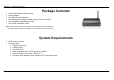
Section 1 - Product Overview Package Contents • • • • • • DSL-2640U Wireless ADSL Router Power Adapter CD-ROM with User Manual One twisted-pair telephone cable used for ADSL connection One straight-through Ethernet cable One Quick Installation Guide Note: Using a power supply with a different voltage rating than the one included with the DSL-2640U will cause damage and void the warranty for this product.
Section 1 - Product Overview 11 Features • PPP (Point-to-Point Protocol) Security – The DSL-2640U ADSL Router supports PAP (Password Authentication Protocol) and CHAP (Challenge Handshake Authentication Protocol) for PPP connections. The Router also supports MSCHAP. • DHCP Support – Dynamic Host Configuration Protocol automatically and dynamically assigns all LAN IP settings to each host on your network. This eliminates the need to reconfigure every host whenever changes in network topology occur.
Section 1 - Product Overview • G.hs (Auto-handshake) – This allows the Router to automatically choose either the G.lite or G.dmt ADSL connection standards. • High Performance – Very high rates of data transfer are possible with the Router. Up to 8 Mbps downstream bit rate using the G.dmt standard. • Full Network Management – The DSL-2640U incorporates SNMP (Simple Network Management Protocol) support for web-based management and text-based network management via an RS-232 or Telnet connection.
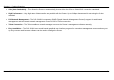
Section 1 - Product Overview Hardware Overview Connections Antenna ADSL Port Use the ADSL cable to connect to the your telephone line (RJ-11 port) Ethernet Port Use the Ethernet port to connect the Router to a computer or an Ethernet LAN WPS Button Push the button to on/off WPS function Power Button Push in to power-on the Router. Push again to power-off the Router. Power Insert Use the adapter shipped with the Router to connect to power source.
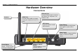
Section 1 - Product Overview Hardware Overview LEDs WLAN A steady green light indicates a wireless connection. A blinking green light indicates activity on the WLAN interface. LAN A solid green light indicates a valid link on startup. This light will blink when there is activity currently passing through the Ethernet port. Power A steady green light indicates the unit is powered on. When the device is powered off it remains dark.
Section 2 – Installation Installation This section will walk you through the installation process. Placement of the Router is very important. Do not place the Router in an enclosed area such as a closet, cabinet, or in the attic or garage. Before You Begin Please read and make sure you understand all the prerequisites for proper installation of your new Router. Have all the necessary information and equipment on hand before beginning the installation.
Section 2 – Installation Installation Notes In order to establish a connection to the Internet it will be necessary to provide information to the Router that will be stored in its memory. For some users, only their account information (Username and Password) is required. For others, various parameters that control and define the Internet connection will be required. You can print out the two pages below and use the tables to list this information.
Section 2 – Installation Additional Software It may be necessary to install software on your computer that enables the computer to access the Internet. Additional software must be installed if you are using the device a simple bridge. For a bridged connection, the information needed to make and maintain the Internet connection is stored on another computer or gateway device, not in the Router itself.
Section 2 – Installation Information you will need from your ADSL service provider Username This is the Username used to log on to your ADSL service provider’s network. Your ADSL service provider uses this to identify your account. Password This is the Password used, in conjunction with the Username above, to log on to your ADSL service provider’s network. This is used to verify the identity of your account.
Section 2 – Installation VPI Most users will not be required to change this setting. The Virtual Path Identifier (VPI) is used in conjunction with the Virtual Channel Identifier (VCI) to identify the data path between your ADSL service provider’s network and your computer. If you are setting up the Router for multiple virtual connections, you will need to configure the VPI and VCI as instructed by your ADSL service provider for the additional connections.
Section 2 – Installation Information you will need about DSL-2640U Username This is the Username needed to access the Router’s management interface. When you attempt to connect to the device through a web browser you will be prompted to enter this Username. The default Username for the Router is “admin.” The user cannot change this. Password This is the Password you will be prompted to enter when you access the Router’s management interface. The default Password is “admin.” The user may change this.
Section 2 – Installation Information you will need about your LAN or computer : Ethernet NIC If your computer has an Ethernet NIC, you can connect the DSL-2640U to this Ethernet port using an Ethernet cable. You can also use the Ethernet ports on the DSL-2640U to connect to other computer or Ethernet devices. DHCP Client status Your DSL-2640U ADSL Router is configured, by default, to be a DHCP server.
Section 2 – Installation Device Installation The DSL-2640U connects two separate physical interfaces, an ADSL (WAN) and an Ethernet (LAN) interface. Place the Router in a location where it can be connected to the various devices as well as to a power source. The Router should not be located where it will be exposed to moisture or excessive heat. Make sure the cables and power cord are placed safely out of the way so they do not create a tripping hazard.
Section 2 – Installation Factory Reset Button The Router may be reset to the original factory default settings by using a ballpoint or paperclip to gently push down the reset button in the following sequence: 1. Press and hold the reset button while the device is powered off. 2. Turn on the power. 3. Wait for 10 seconds and then release the reset button. Remember that this will wipe out any settings stored in flash memory including user account information and LAN IP settings.
Appendix A – Troubleshooting Configuration This section will show you how to configure your new D-Link Router using the web-based configuration utility. Web-based Configuration Utility Connect to the Router The default IP address for ADSL MODEM is: 192.168.1.1; The Subnet Mask is:255.255.255.0. Users can configure ADSL MODEM through an Internet browser. ADSL MODEM can be used as gateway and DNS server; users need to set the computer’s TCP/IP protocol as follow: 1.
Appendix A – Troubleshooting Device Info To access the Device Info window, click either the Device Info or Summary button in the Device Info directory.
Appendix A – Troubleshooting Summary To access the Router’s first Summary window, click the Summary button in the Device Info directory. This window displays the current status of your DSL connection, including the software version, LAN IP address, and DNS server address.
Appendix A – Troubleshooting WAN To access the WAN Info window, click the WAN button in the Device Info directory. This window displays the current status of your WAN connection.
Appendix A – Troubleshooting Statistics To access the Router’s first Statistics window, click the Statistics button in the Device Info directory. This window displays the Router’s LAN statistics. Click the Reset Statistics button to refresh these statistics. This window displays the Router’s WAN statistics. Click the Reset Statistics button to refresh these statistics.
Appendix A – Troubleshooting This window displays the Router’s XTM statistics. Click the Reset button to refresh these statistics.
Appendix A – Troubleshooting This window displays the Router’s xDSL statistics. Click the Reset Statistics button to refresh these statistics.
Appendix A – Troubleshooting Route To access the Device Info – Route window, click the Route button in the Device Info directory. This read-only window displays routing info. ARP To access the Device Info – ARP window, click the ARP button in the Device Info directory. This read-only window displays Address Resolution Protocol info. DHCP To access the Device Info – DHCP Leases window, click the DHCP button in the Device Info directory. This read-only window displays DHCP lease info.
Appendix A – Troubleshooting Advanced Setup This chapter include the more advanced features used for network management and security as well as administrative tools to manage the Router, view status and other information used to examine performance and for troubleshooting. Layer2 Interface To access the DSL ATM Interface Configuration window, click the ATM Interface button in the Layer2 Interface directory. This window is used to configure the ATM interface.
Appendix A – Troubleshooting ATM Interface The ATM PVC Configuration window allows you to set up ATM PVC configuration. Enter Virtual Path Identifier,and Virtual Channel Identifier. The VPI and VCI values should be provided by your ISP. This window also allows you to select DSL Link Type, PPPoA、IpoA and EoA (EoA is for PPPoE, IPoE, and Bridge) Use the drop-down menu to select the desired Encapsulation Mode.. Click the Apply / Save button to Save.
Appendix A – Troubleshooting WAN Service To access the Wide Area Network (WAN) Service Setup window, click the WAN Service button in the Advanced Setup directory. This window is used to configure the WAN interface. You can add and delete WAN interface on this window. If you are setting up the WAN interface for the first time, click the Add button.
Appendix A – Troubleshooting The WAN Service Interface Configuration Configuration window allows select a layer 2 interface for this service. Click the Next button to continue.
Appendix A – Troubleshooting This window allows you to select the appropriate connection type. The choices include PPP over ATM (PPPoA), PPP over Ethernet (PPPoE), IP over Ethernet (IpoE), IP over ATM (IPoA), and Bridging. WAN Service Configuration – PPPoE Click the PPP over Ethernet (PPPoE) radio button on this window. This window also allows you to use the drop-down menu to enable IPv6 service. Click the Next button to continue.
Appendix A – Troubleshooting WAN Service Configuration – PPPoE This window allows you to set the username and the password for your PPP connection. This information is obtained from your ISP. Additional settings on this window will also depend on your ISP. Click the Next button to continue.
Appendix A – Troubleshooting WAN Service Configuration – PPPoE Default gateway interface list can have multiple WAN interfaces served as system default gateways but only one will be used according to the priority with the first being the higest and the last one the lowest priority if the WAN interface is connected. Priority order can be changed by removing all and adding them back in again. Click the Next button to continue.
Appendix A – Troubleshooting WAN Service Configuration – PPPoE This summary window allows you to confirm the settings you have just made. Click the Apply / Save button to save your new PPP over Ethernet settings and restart the Router.
Appendix A – Troubleshooting WAN Service Configuration – IPoE Click the IP over Ethernet radio button on this window. Click the Next button to continue.
Appendix A – Troubleshooting WAN Service Configuration – IPoE This window allows you to configure the WAN IP settings. This information is obtained from your ISP. Click the Next button to continue.
Appendix A – Troubleshooting WAN Service Configuration – IPoE This window allows you to enable or disable Network Address Translation and a firewall for your Router. In addition, you can enable or disable IGMP multicasting. Click the Next button to continue.
Appendix A – Troubleshooting WAN Service Configuration – IPoE Select DNS Server Interface from available WAN interfaces OR enter static DNS server IP addresses for the system. In ATM mode, if only a single PVC with IPoA or static IPoE protocol is configured, Static DNS server IP addresses must be entered.
Appendix A – Troubleshooting WAN Service Configuration – BRIDGING Click the Bridge radio button on this window. Click the Next button to continue.
Appendix A – Troubleshooting WAN Service Configuration – BRIDGING This summary window allows you to confirm the bridging settings you have just made. Click the Apply /Save button to save your new bridging settings and restart the Router. WAN Service Configuration – PPPoA This window allows you to enter service description. Click the Next button to continue.
Appendix A – Troubleshooting WAN Service Configuration – PPPoA This window allows you to set the username and the password for your PPP connection. This information is obtained from your ISP. Additional settings on this window will also depend on your ISP. Click the Next button to continue.
Appendix A – Troubleshooting WAN Service Configuration –PPPoA Default gateway interface list can have multiple WAN interfaces served as system default gateways but only one will be used according to the priority with the first being the higest and the last one the lowest priority if the WAN interface is connected. Priority order can be changed by removing all and adding them back in again. Click the Next button to continue.
Appendix A – Troubleshooting WAN Service Configuration – PPPoA This summary window allows you to confirm the settings you have just made. Click the Apply / Save button to save your new PPP over ATM settings and restart the Router.
Appendix A – Troubleshooting WAN Service Configuration – IPoA This window allows you to enter service description. Click the Next button to continue. WAN Service Configuration – IPoA This window allows you to configure the WAN IP settings. This information is obtained from your ISP. Click the Next button to continue. WAN Service Configuration – IPoA This window allows you to enable or disable Network Address Translation and a firewall for your Router.
Appendix A – Troubleshooting WAN Service Configuration – IPoA Default gateway interface list can have multiple WAN interfaces served as system default gateways but only one will be used according to the priority with the first being the higest and the last one the lowest priority if the WAN interface is connected. Priority order can be changed by removing all and adding them back in again. Click the Next button to continue.
Appendix A – Troubleshooting WAN Service Configuration – IPoA This summary window allows you to confirm the settings you have just made. Click the Save/Reboot button to save your new IP over ATM settings and restart the Router.
Appendix A – Troubleshooting PPTP To access the PPTP Setting window, click the PPTP button in the Advanced Setup directory. To set up Point-to-Point Tunnel Protocol, tick the Enable check box, enter the appropriate information in the fields offered, and then click the Apply / Save button when you are finished.
Appendix A – Troubleshooting LAN You can configure the LAN IP address to suit your preference. Many users will find it convenient to use the default settings together with DHCP service to manage the IP settings for their private network. The IP address of the Router is the base address used for DHCP. In order to use the Router for DHCP on your LAN, the IP address pool used for DHCP must be compatible with the IP address of the Router.
Appendix A – Troubleshooting To access the IPv6 LAN Auto Configuration window, click the IPv6 AutoConfig button in the LAN directory. This window allows you to set up IPv6 LAN Auto Configuration. When you are finished, click the Apply / Save button.
Appendix A – Troubleshooting NAT To access the Network Address Translation (NAT) Setup window, click the NAT button in the Advanced Setup directory. The NAT button appears when configuring WAN interface in PPPoA, PPPoE, IPoE or IPoA. Virtual Servers This window is used to configure virtual server. You can add, delete, and modify virtual server on this window. If you are setting up the virtual server, click the Add button.
Appendix A – Troubleshooting You can configure the service settings on this window by clicking the Select a Service radio button and then using the drop-down list to choose an existing service, or by clicking the Custom Server radio button and entering your own Application Rule in the field provided. Click Apply / Save when you are finished with the virtual server configuration.
Appendix A – Troubleshooting You can configure the port settings on this window by clicking the Select an application radio button and then using the drop-down list to choose an existing application, or by clicking the Custom application radio button and entering your own Application Rule in the field provided. Click Save/Apply when you are finished with the port setting configuration. The new Application Rule will appear in the Port Triggering table.
Appendix A – Troubleshooting Security To access the Security window, click the Security button in the Advanced Setup directory. The Security button appears after configuring WAN interface in PPPoA, PPPoE, IPoE or IPoA. IP Filtering The IP Filtering button appears when configuring WAN interface in PPPoA, PPPoE, IPoE or IPoA. IP Filtering - Outgoing This window allows you to create a filter rule of Outgoing. Click change default policy to change the mode of policy.
Appendix A – Troubleshooting Enter the information in the section. Explanations of parameters are described below. Click the Apply / Save button to add the entry in the Active Outbound IP Filtering table. Filters Parameter Filter Name IP Version Protocol Source IP address[/prefix length] Source Port (port or port:port) Destination IP address[/prefix length] Destination Port (port or port:port) Description Enter a name for the new filter.
Appendix A – Troubleshooting IP Filtering – Incoming This window allows you to create a filter rule of Incoming. Click change default policy to change the mode of policy. Now default policy is ACCEPT, it means all incoming IP traffic from WAN is accepted, but some IP traffic can be blocked by setting up filters. If you are setting up the incoming IP filtering, click the Add button.
Appendix A – Troubleshooting Enter the information in the section. Explanations of parameters are described below. Click the Apply / Save button to add the entry in the Active Inbound IP Filtering table. Filters Parameter Filter Name IP Version Protocol Source IP address[/prefix length] Source Port (port or port:port) Destination IP address[/prefix length] Destination Port Description Enter a name for the new filter.
Appendix A – Troubleshooting (port or port:port) Inbound Filter rule. Parental Control Use this window to deny access to specified MAC address. If you are setting up the MAC address blocking, click the Add button. MAC address is a specially formatted text string (xx:xx:xx:xx:xx:xx) that uniquely identification of a device. This section will allow users to block devices with certain MAC addresses on the LAN.
Appendix A – Troubleshooting URL Filter This window allows you to set up URL Filter on the Router. Choose URL List Type Exclude or Include first and click Add button. Enter the URL address and port number then click Apply / Save to add the entry to the URL filter.
Appendix A – Troubleshooting Quality of Service QoS or Quality of Service allows your Router to help prioritize the data packet flow in your Router and network. This is very important for time sensitive applications such as VoIP where it may help prevent dropped calls. Large amounts of non-critical data can be scaled so as not to affect these prioritized sensitive real-time programs.
Appendix A – Troubleshooting Queue Config Click the Add button to add a QoS Queue Configuration table entry. This window allows you to configure a QoS queue entry and assign it a specific network interface. Click the Apply / Save button to save and activate the filter.
Appendix A – Troubleshooting QoS Classification Choose Add or Remove to configure network traffic classes. Use this window to create a traffic class rule to classify the upstream traffic, assign a queue that defines the precedence and the interface, and optionally overwrite the IP header DSCP byte. A rule consists of a class name and at least one condition. Please remember that all of the specified conditions on this window must be met for the rule to take effect.
Appendix A – Troubleshooting Routing To access the Routing windows, click the Routing button in the Advanced Setup directory. Default Gateway Default gateway interface list can have multiple WAN interfaces served as system default gateways but only one will be used according to the priority with the first being the highest and the last one the lowest priority if the WAN interface is connected. Priority order can be changed by removing all and adding them back in again.
Appendix A – Troubleshooting Enter the static routing information for an entry to the routing table. Click the Apply / Save button when you are finished. Policy Routing Click the Add button on the Policy Routing Settup window to access the following window displayed on the next page.
Appendix A – Troubleshooting Enter the Policy Routing information.Click the Apply / Save button when you are finished. RIP To activate RIP for the device, select the Enabled radio button for Global RIP Mode. To configure an individual interface, select the desired RIP version and operation, followed by placing a check in the 'Enabled' checkbox for the interface. Click the Save/Apply button to save the configuration, and to start or stop RIP based on the Global RIP mode selected.
Appendix A – Troubleshooting DNS To access the DNS windows, click the DNS button in the Advanced Setup directory. The DNS button appears when configuring WAN interface in PPPoA, PPPoE, MER or IPoA. DNS Server Select DNS Server Interface from available WAN interfaces OR enter static DNS server IP addresses for the system. In ATM mode, if only a single PVC with IPoA or static IPoE protocol is configured, Static DNS server IP addresses must be entered.
Appendix A – Troubleshooting The Router supports Dynamic DNS (Dynamic Domain Name Service). The Dynamic DNS service allows a dynamic public IP address to be associated with a static host name in any of the many domains, allowing access to a specified host from various locations on the Internet. This is enabled to allow remote access to a host by clicking a hyperlinked URL in the form hostname.dyndns.
Appendix A – Troubleshooting Enter the required DDNS information, click the Apply / Save button to save the information. Note DDNS requires that an account be setup with one of the supported DDNS servers prior to engaging it on the Router. This function will not work without an accepted account with a DDNS server.
Appendix A – Troubleshooting DSL To access the DSL Settings window, click the DSL button in the Advanced Setup directory. This window allows you to select the desired modulation, phone line pair, and capability. Click the Apply / Save button when you are finished. Click the Advanced Settings button to select a DSL test mode.
Appendix A – Troubleshooting Select the desired DSL test mode and then click the Apply button. Click the Tone Selection button to modify the upstream and downstream tones. Select the appropriate upstream and downstream tones for your ADSL connection. Click the Apply button to let your settings take effect.
Appendix A – Troubleshooting UPNP To access the UPnP Configuration window, click the UPnP button in the Advanced Setup directory. This window allows you to Config UPnP Proxy. Click the Apply / Save button when you are finished. DNS Proxy To access the DNS Proxy Configuration window, click the DNS Proxy button in the Advanced Setup directory. This window allows you to Config DNS Proxy. Click the Apply / Save button when you are finished.
Appendix A – Troubleshooting Interface Group Interface Group supports multiple ports to PVC and bridging groups. Each group will perform as an independent network. To support this feature, you must create mapping groups with appropriate LAN and WAN interfaces using the Add button. The Remove button will remove the grouping and add the ungrouped interfaces to the Default group. Only the default group has IP interface. Click Add to do advanced settings.
Appendix A – Troubleshooting IPSec To access the IPSec Tunnel Mode Connections window, click the IPSec button in the Advanced Setup directory. This window allows you to configure IPSec.
Appendix A – Troubleshooting This window allows you to advanced settings.
Appendix A – Troubleshooting Multicast To access the IGMP Configuration window, click the Multicast button in the Advanced Setup directory. Enter IGMP protocol configuration fields if you want modify default values shown below.
Appendix A – Troubleshooting Wireless Press Wireless in the left menu to enter wireless section. You can select to configure wireless setup, security and management. Basic This page allows you to configure basic features of the wireless LAN interface. You can enable or disable the wireless LAN interface, hide the network from active scans, set the wireless network name (also known as SSID) and restrict the channel set based on country requirements.
Appendix A – Troubleshooting Security This page allows you to configure security features of the wireless LAN interface. You may setup configuration manually or through WiFi Protcted Setup(WPS) You can select to configure WEP encryption, Shared, 802.1x, WPA, and WPA2 authentication.
Appendix A – Troubleshooting MAC Filter This page can help you to allow or deny certain MAC addresses to pass through or block out. Click Add to see the following page. Enter MAC Address and click Apply / Save to add the MAC address to MAC filter.
Appendix A – Troubleshooting Wireless Bridge This page allows you to configure bridge features of the wireless LAN. Click Refresh to update the remote bridges. Click Apply / Save to save the settings. \ D-Link DSL-2640U User Manual 76
Appendix A – Troubleshooting Advanced This page allows you to configure advanced wireless LAN interface. Configuring these settings may increase the performance of your router but if you are not familiar with networking devices and protocols, this section should be left at its default settings. Click Apply / Save to save the settings.
Appendix A – Troubleshooting Station Info This page shows the authenticated wireless stations and their status. Click Refresh to update the information.
Appendix A – Troubleshooting Diagnostics Your modem is capable of testing your DSL connection with access to Diagnostics. This window is used to test connectivity of the Router.
Appendix A – Troubleshooting Management The Management directory features an array of options designed to help you get the most out of your Router. Settings To access the Settings - Backup window, click the Settings button in the Management directory. This window allows you to backup your DSL Router configurations. Click the Backup Settings button to save your Router configurations to a file on your computer. This window allows Update DSL router settings.
Appendix A – Troubleshooting System Log These windows allow you to view the System Log and configure the System Log options. To access the System Log window, click the System Log button in the Management directory. Click the View System Log button to view the System Log. Click the Configure System Log button to configure the System Log options. Click on the Refresh button to refresh the system log settings.
Appendix A – Troubleshooting The system log displays chronological event log data. The event log can be read from local host or sent to a System Log server. The available event severity levels are: Emergency, Alert, Critical, Error, Warning, Notice, Informational, and Debugging. This window allows you to log selected events. When you are finished, click the Apply / Save button. SNMP Agent To access the SNMP – Configuration window, click the SNMP Agent button in the Management directory.
Appendix A – Troubleshooting Simple Network Management Protocol allows a management application to retrieve statistics and status from the SNMP agent in the Router. When you are finished, click the Save/Apply button.
Appendix A – Troubleshooting TR-069 Client To access the TR-069 Client – Configuration window, click the TR-069 Client button in the Management directory. Simple Network Management Protocol allows a management application to retrieve statistics and status from the TR-069 client in the Router. When you are finished, click the Save/Apply button.
Appendix A – Troubleshooting Internet Time To access the Time settings window, click the Internet Time button in the Management directory. This window allows you to set the Router’s time configuration. When you are finished, click the Save/Apply button.
Appendix A – Troubleshooting Access Control To access the Access Control windows, click the Access Control button in the Management directory. Passwords This window allows you to change the password on the Router. When you are finished, click the Save/Apply button.
Appendix A – Troubleshooting Update Software To access the Tools - Update Software window, click the Update Software button in the Management directory. This window allows you to update the Router’s software. Reboot To access this window, click the Reboot button in the Management directory. To save your settings and reboot the system, click the Reboot button.
Appendix A – Troubleshooting Troubleshooting This chapter provides solutions to problems that might occur during the installation and operation of the DSL-2640U. Read the following descriptions if you are having problems. (The examples below are illustrated in Windows® XP. If you have a different operating system, the screenshots on your computer will look similar to the following examples.) 1. How do I configure my DSL-2640U Router without the CD-ROM? • • • • Note: 2.
Appendix A – Troubleshooting 4. Why can’t I get an Internet connection? For ADSL ISP users, please contact your ISP to make sure the service has been enabled/connected by your ISP and that your ISP username and password are correct. 5. What can I do if my router can’t be detected by running installation CD? • • • • Note: Ensure the Router is powered on. Check that all the cables are firmly connected at both ends and all LEDs work correctly.
Appendix B - Networking Basics Networking Basics Check Your IP Address After you install your new D-Link adapter, by default, the TCP/IP settings should be set to obtain an IP address from a DHCP server (i.e. wireless router) automatically. To verify your IP address, please follow the steps below. Click on Start > Run. In the run box type cmd and click on the OK. At the prompt, type ipconfig and press Enter. This will display the IP address, subnet mask, and the default gateway of your adapter.
Appendix B - Networking Basics Statically Assign an IP Address If your DHCP is disabled, or you need to assign a static IP address, please follow the steps below: Step 1 Windows® XP - Click on Start > Control Panel > Network Connections. Windows® 2000 - From the desktop, right-click on the My Network Places > Properties. Step 2 Right-click on the Local Area Connection which represents your D-Link network adapter and select Properties. Step 3 Highlight Internet Protocol (TCP/IP) and click on the Properties.
Appendix C – Technical Specification Technical Specifications ADSL Standards • • • • Data Transfer Rate ANSI T1.413 Issue 2 ITU G.992.1 (G.dmt) AnnexA ITU G.992.2 (G.lite) Annex A ITU G.994.1 (G.hs) • • • ADSL2 Standards • • ITU G.992.3 (G.dmt.bis) Annex A ITU G.992.4 (G.lite.bis) Annex A • Wireless Transfer Rates ADSL2+ Standards • ITU G.992.5 Annex A/M Protocols • • • • • • • • • • IEEE 802.
Federal Communications Commission Statement This device complies with FCC Rules Part 15. Operation is subject to the following two conditions: ‧ This device may not cause harmful interference, and ‧ This device must accept any interference received, including interference that may cause undesired operation. ‧ This equipment has been tested and found to comply with the limits for a class B digital device, pursuant to Part 15 of the Federal Communications Commission (FCC) rules.