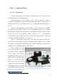
AGH University of Science and Technology Faculty of Electrical Engineering, Automatics, Computer Science and Electronics Department of Electrical Machines Name: Jakub Wójcik Faculty: Electrical Engineering Specialization: Computer Engineering In Electrical Systems The conception and the implementation of control system for servomotor with application of wireless network Master’s thesis written under the direction of prof. dr hab.
STATEMENT OF ORIGINALITY Aware of criminal liability for making untrue statements I declare that the following thesis was written personally by myself and that I did not use any sources but the ones mentioned in the dissertation itself. ………………………………… /date/ ………………………………..
Sincere thanks to prof. dr hab.
Table of Contents Unit I A Little bit of theory ........................................................................................... 6 1.1. Servo – What and how ....................................................................................................... 6 1.2. Wireless Network – 802.11 ................................................................................................ 9 Unit II Hardware/software ..........................................................................
Introduction World runs faster and faster everyday. New inventions appear in every corner of the world. This is the fact. But the reason why can not be more prosaic. People are lazy… Everybody wants not to have to do as many things as possible. That is why intelligent buildings becomes more and more popular, cars park themselves, vacuum cleaners drive under our feet and even more. We simply do not know in how many different fields we are being replaced by machines.
Unit I A Little bit of theory 1.1. Servo – What and how To start solving the problem of wireless control system for servomotor we must be aware of what the servomechanism really is. Servomechanism1 it is an automatic control system in which the output is constantly or intermittently compared with the input through feedback so that the error or difference between the two quantities can be used to bring about the desired amount of control. The key to understand this is a term “feedback” or “error-correction”.
designed to take position angle between 0 and 180 degrees. Most mechanisms have limiters that do not allow a greater swing of the shaft. In fact, servos are mainly used in positioning systems such as cameras, electronic equipment equipped with mechanical positioning, aircraft models to set primaries. Those applications put pressure on accuracy, ease of operation and low power consumption instead of full rotation. Wherever full rotation is needed stepper motors or DC motors are used.
of the servos is a shaft of 1.5ms pulse length for the center position set. Deviate from this value causes the shift shaft move to the left or to the right. In most motors pulses are in the range between 1 - 2ms. In practice (servo used in this project is Hextronik HXT900) it appears that for the zero position to be maintained the 0.95ms pulse is needed, the middle position - 1.5ms, 1.95ms for final position. Figure 3. Servo motor system schematics [source: http://www.engineersgarage.
1.2. Wireless Network – 802.11 Since the beginning wires were the main restriction of every control mechanism. Due to this limitation human factor at specified time and place to control every wired device, or expensive and complicated wired network is needed. But what if we were able to bypass this “little” obstacle? One person controlling many devices spread over a large area without necessity of additional equipment. To achieve this goal wireless networks were created.
2Mbps. The third generation which we use nowadays operates on the same band as the second generation, 2,4GHz. The world first official standard IEEE 802.11 with data rates of 1 and 2 Mbps was established in 1997 seven years after IEEE 802 Executive Committee established the 802.11 Working Group to create a wireless local area network (WLAN) standard. That is history. Now let‟s focus on the protocol itself. The 802.
Unit II Hardware/software 2.1. Open Source – nice, simple and free Since the beginning of the computer history the intellectual property rights were the issue. Every man wants to be rewarded for hard work, that is fully understandable. But due to that fact accessibility to the new technology in fast changing IT world is restricted for those who do not have enough resources to be up to date. This is where Open Source license software comes across.
2.2. Arduino Uno „Arduino is an open-source electronics prototyping platform cased on flexible, easy-to-use hardware and software. It’s intended for artists, designers, hobbyists and anyone interested in creating interactive objects or environments”. Those are the very first words we meet on the Arduino project website4 and after familiarizing myself with this “new” platform for me I can say they are very truth.
provided mostly in wiki-like and forum form which is bothersome when meeting problems during development process. Experience shared with other developers helps to improve following versions of Arduino board but lack of the old fashioned technical specification forced me to look through countless data in order to find needed information. The Arduino Uno is microcontroller equipped with ATmrga328.
communication over USB (available on digital pins 0 RX and 1 TX). After connecting to the PC it appears as a virtual com port to software on the computer. No additional drivers are needed as „8U2 firmware uses the standard USB COM drivers. To control data flow RX and TX LEDs will flash when data is being transmitted via USB-to-serial chip and USB connection to the computer (not for serial communication on pins 0 and 1). As it comes to programming Arduino Uno can be programmed with software provided.
There are many reasons for choosing this solution as base for whole project. First of all I have assumed that in this case reinventing the wheel is not a good idea. As I am not electronic engineer creating board like this alone bears significant risk of failing due to the lack of experience. Second one is the wireless shield provided by another producer with whole set of technical documentation. And the third one, Arduino Uno provides far more than I need for a reasonable price.
2.3. WiFly Shield As Arduino Uno which plays role of the motherboard is very capable of talking and listening (controlling I/O), it is not equipped with key for this project communication capability which is wireless IEEE 802.11 protocol. To achieve this requirement I was forced to look for addition that does. After few days of searching I have come up with WiFly shield form SparkFun Electronics that allows to connect to the 802.11b/g wireless network. The revision of WRL-09954 Figure 6.
- “Talking Wireless Serever Tutorial8”, - Two forums Arduino9 and SparkFun10 Overview - Fully Qualified and Wi-Fi Certified 2.4GHz IEEE 802.11b/g transceiver, - High throughput, up to 4Mbps sustained data rate with TCP/IP and WPA2, - Ultra-low power (4µA sleep, 40mA Rx, 210mA max Tx), - On board ceramic chip antenna and U.
2.4 CodeGear Delphi Next decision I had to make was the way of communication from the side of the computer. As nowadays the programming languages offers practically the same capabilities (when talking about such a simple project), I have chosen by my programming experience CodeGear‟s Delphi. It is object language based on Pascal. Unfortunately I do not have full version, so I Figure 7. CodeGear Delphi 2009 by Embarcadero Technologies. have to use trial version of Delphi 2009 Proffesional.
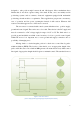
Unit III Conception of Control System 3.1. The idea Every project begins with the idea. In this case the main idea was to control servomotor via wireless IEEE 802.11 network. To achieve this goal following establishments has been considered. Main schematic diagram as follows. Figure 9. Schematic diagram of the control system for servomotor with application of wireless network 1. Every PC with installed WCC (WirelessControlClient) application on it is enough.
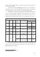
Figure 10. D-Link DSL-G684T ADSL2+ 54M Wireless Router w/ 4 Port 10/100 Switch [source: DSL-G684T Manual] Technical Specifications: Picture 11.
Picture 12. Physical and Environmental Specification [source: DSL-G684T Manual] Picture 13.
3. As a control system I have used Arduino Uno mainboard with additional WiFly SparkFun shield. Both are described with technical specifications in Unit II. For the project the control system is called WCS (WirelessControlSystem). 4. To control I have chosen two simple hobby 9 gram servomotors HXT900 from HEXTRONIK. The main factor was low cost and relatively good construction. Figure 14. Hextronik HXT900 Modulation: Analog Torque: 4.8V: 1.6 kg-cm Speed: 4.8V: 0.12 sec/60˚ Weight: 9.
5. As all new inventions without the suggestion of application are rather meaningless, I have decided to make this project a little bit more “alive” by adding one. To do this the BlackBox was created. Inside a small photocell and one servomotor are hidden. The purpose of this box is to maintain previously set intensity of light inside. Top of the box works like blinds in the windows. Servomotor controls obscure of the blinds while photocell checks light intensity.
3.2 Applications The main issue of new inventions are the applications. History of human kind is full of meaningless gadgets created without explicit purpose that land on shelves and are never used again. I have spent many hours of work and hard thinking on this project and I would like it not to happen. That is why here are just a few examples of application of the control system of servomotors via wireless network.
subject, as well as capabilities of creating really complicated advanced projects that demands advanced knowledge for students familiar with the subject. Smart Houses – to connect automation of the smart house to the computer network inside intermediary system is needed. This is the place for application of the wireless servo control system.
Unit IV 4.1 Implementation of Control System Hardware Process of creation of the hardware aspect of the project was rather not complicated. It consisted of two parts, WCS (main control box) and BlackBox. In first case as both electronic boards came completed the only two things I had to do were soldering the headers to the WiFly shield and creating reset button with corresponding LED, connect pins for servos and photocell and casing with place for antenna.
two legs, connection pin to voltage, so that we read a HIGH. For the convenience of the user additional LED is placed into the circuit. When button is closed LED starts to blink. In addition, when reset takes place LED blinks 3 to 6 times fast in a row to confirm. Servomotor pins To control servos simple connection consisting of three cables is needed. Ground, power and control signal. I have placed two sets of pins directly to control two servos.
the absence of light, its resistance increases dramatically. In this case due to the analog input photocell is connected to its range is between 0 and 1023. BlackBox blinds To set light intensity simple single blind controlled by servomotor is Figure 20. Concept of the hysteresis in application to photocell adopted. As we can see on the photograph round blind half transparent half black allows us to use 180˚ control range of the servomotor.
servomotor any other way will damage it. To place servomotor with blind on it I have used a stand based on three screws with spring bumpers. When the adjustment of height is needed we just screw on or off the overlays. The springs persist stand from falling down while overlays determine the maximal height. Underneath the stand the photocell is placed. Power supply To power up control system with two servomotors USB computer port is not enough.
Model : Portable Power Pack D.2200. Input : 5V Micro USB Output : 5-5.5V – 700mA Battery Type : 3.7V – 2200mAh Finished Control System After finishing hardware preparations two boxes were created. Figure 26. BlackBox - final Figure 25.
4.2 Software The software prepared for the project consists of two parts. First one is the application written for control board. The second is the software written in Embarcadero Delphi 2009, pc win32 application that allows us to communicate with control system over wireless network via telnet protocol. Below there is a block diagram of the Arduino Uno software.
ARDUINO It all began with the installation of the Arduino board on my PC. As it is written in “getting started”11 guide all went smooth and easy. The only thing I had do to after downloading drivers and software was to navigate to the “ArduinoUNO.ini” file located in drivers folder to install proper drivers. In the next step I had to familiarize myself with the programming environment supplied with Arduino board. Arduino alpha v.0.0.2.
Second one is “viod setup()” function. This one is activated only once, at the start of the board. Third one is “void loop()” function which is call over and over again by the Arduino itself. This is the place for our main program. And the fourth one are all the other functions we need for our application to work. All of them are called out in void loop() or other nested functions. Shortened applications listing: 1.
myservo.attach(9); myservo1.attach(8); myservo.write(myservo_pos); myservo1.write(myservo_pos); At the beginning to control servomechanism it needs to be defined. To do this command “attach” is used. Digital pins 8 and 9 are reserved for servos. After defining output we set the beginning position at 0˚ by “write” command.
if(SPI_Uart_Init()) //Test SC16IS750 communication { Serial.println("Bridge initialized successfully!"); } else{ Serial.println("Could not initialize bridge, locking up.\n\r"); while(1); } autoconnect(); At the end of the setup section we check if the SPI-to-UART bridge is initialized successfully (SPI_Uart_Init()) and afterwards if wireless connection with the predefined configuration is set up properly(autoconnect()). 3.
if ((get == 1)||(post == 1)) { Serial.println("\n\rConnection opened.
SPI_Uart_println("exit"); delay(500); Flush_RX(); } In the earlier version of the project communication was based on the HTTP instead of the telnet protocol. That is why in this section an example of stored html is placed. I left this part of code to show additional possible functionality, which is handling website with status data, or as in example even servo control ability. In my opinion, as an additional functionality, this is very powerful tool. 4.
// Exit command mode if we haven't already SPI_Uart_println(""); SPI_Uart_println("exit"); delay(500); // Enter command mode SPI_Uart_print("$$$"); delay(500); SPI_Uart_print("set opt password 0"); delay(500); Serial.print("Set wlan password to none"); // Set ssid SPI_Uart_print("set wlan ssid "); SPI_Uart_println(ssid); delay(500); Serial.print("Set wlan ssid to "); Serial.println(ssid); // Set channel to SPI_Uart_print("set wlan channel "); SPI_Uart_println(channel); delay(500); Serial.
Serial.print("Set security phrase to "); Serial.println(auth_phrase); // Set localport to SPI_Uart_print("set i l "); SPI_Uart_println(port_listen); delay(500); Serial.print("Set IP localport to "); Serial.
itoa (myservo1.read(), val2, 10); SPI_Uart_print("servo1="); SPI_Uart_print(val2); delay(90); } // auto photocell if (ph == 1){ for(i = 0; i < 180; i++){ val = analogRead(photoPin); if(ph_val!=val){ if(ph_val=0)){ myservo.write(myservo.read()-1); } } if(ph_val>val+5){ if((myservo.read()+1<=180)&&(myservo.read()+1>=0)){ myservo.write(myservo.read()+1); } } delay(10); } } } if(SPI_Uart_ReadByte(LSR) & 0x01){ Serial.println("Client request...
else{ return 0; } } Above Have_Client(void) is presented. This is the first procedure that is called in the loop section to check whether client requests something from our control system. After being called status of the hard reset button is checked. If it is pressed for 4 to 6 seconds default setting to WiFly shield are written and saved. Otherwise nothing happens besides LED blinking. For changes to be applied, reset of the control system is required.
void Parse_Request(void) { int j = 0, k = 0; String temp = ""; inc_data_all = ""; post = 0; get = 0; while(j < 4000) { if((SPI_Uart_ReadByte(LSR) & 0x01)) { incoming_data = SPI_Uart_ReadByte(RHR); Serial.print(incoming_data,BYTE); if ((inc_data_all.indexOf("POST") != 1)&&(k==0)) { post = 1; get = 0; k = 1; } if ((inc_data_all.indexOf("GET") != 1)&&(k==0)) { post = 0; get = 1; k = 1; } if (inc_data_all.
} else { j++; } } // if (post == 1) // check if incoming package is POST // // { inc_data_all.trim(); // // if (inc_data_all.indexOf("poh=") != -1) // new position for servo // // { if (inc_data_all.indexOf("&", inc_data_all.indexOf("poh=")+4) == -1) // { // k = inc_data_all.length()+1; // Serial.println("k=length+1: "); // Serial.println(k); // } // else // { // k = inc_data_all.indexOf("&", inc_data_all.indexOf("poh=")+4)+1; // Serial.println("k=indexOf: "); // Serial.
// myservo_pos = 0; // //convertion ascii to integer // for (int i = 0; i < temp.length()-1; i++) // { // myservo_pos = (myservo_pos * 10) + temp.charAt(i) - '0'; // } // // Serial.println(myservo_pos); // myservo.write(myservo_pos); // } // SPI_Uart_print("$$$"); // delay(500); // SPI_Uart_println("close"); // delay(1000); // SPI_Uart_println("exit"); // delay(500); // Flush_RX(); // inc_data_all = ""; // } if (inc_data_all.
temp.charAt(i) - '0'; } Serial.println(myservo_pos); myservo.write(myservo_pos); SPI_Uart_print("OK"); Flush_RX(); inc_data_all = ""; } if (inc_data_all.indexOf("poz=") != -1) // new position for servo from telnet { temp = ""; for (j = inc_data_all.indexOf("poz=")+4; j < inc_data_all.length()-1; j++) { temp += inc_data_all.charAt(j); } myservo_pos = 0; //convertion ascii to integer for (int i = 0; i < temp.length()-1; i++) { myservo_pos = (myservo_pos * 10) + temp.charAt(i) - '0'; } Serial.
if (inc_data_all.indexOf("photo") != -1) { if (inc_data_all.indexOf("photo=1") != -1){ photo = 1; } else{ photo = 0; } inc_data_all = ""; SPI_Uart_print("command-OK"); } if (inc_data_all.indexOf("servo=") != -1) { if (inc_data_all.indexOf("servo=1") != -1){ servo = 1; } else{ servo = 0; } inc_data_all = ""; SPI_Uart_print("command-OK"); } if (inc_data_all.indexOf("ph=off") != -1){ ph=0; Flush_RX(); inc_data_all = ""; SPI_Uart_print("command-OK"); } if (inc_data_all.
temp += inc_data_all.charAt(j); } ph=1; ph_val=0; for (int i = 0; i < temp.length()-1; i++) { ph_val = (ph_val * 10) + temp.charAt(i) - '0'; } Flush_RX(); inc_data_all = ""; SPI_Uart_print("command-OK"); } } Parse_Request is a function that does not return any value. It is responsible for determining the syntax of incoming request/command. There are few possible command syntax listed below. - GET/POST – if incoming request is sent by web browser we need to check the type of the request.
- TELNET – to communicate with control system telnet protocol is used. When command sent to Arduino is not one from above it is recognized as a telnet command and send directly to WiFly shield. It is done to be able to change properties of wireless connection stored within RN-131C module. void Save_To_EEPROM(String data) { int start = 0; byte c = 255; for (int i = 0; i < 1023; i++) { if (EEPROM.read(i) == 255) { start = i + 1; break; } } for (int i = 0; i < data.length(); i++) { c = data.
void Read_EEPROM() { for (int i = 0; i < 1023 ; i++) { Serial.print(EEPROM.read(i), BYTE); } } During designing process issue with saving data that will not disappear after cutting out the power appeared. To solve this problem I have created set of functions that allows us to save data to 1024 bytes of flash memory shared on Arduino Uno. Despite the fact that in final version it is not used I have left this part of code as a support for future developments of the code.
DELPHI (win32) In the second stage the time for pc application has come. Delphi is the objectoriented programming language based on Pascal. Version I have used was the 2009 Professional trial that allows to test all means necessary for the project. Before the beginning I have received permission from the official Embarcadero distributor in Poland to use trial version in this project. 1.
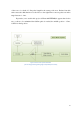
4. Login As simple as it sounds to enter software we need to log in. This most basic protection prevents unwanted people or software to take control over our client software. To level up security separate algorithm to encode login password and Figure 31. WirelessControlClient Login screen are implemented. Both of them are stored inside “setup.ini” file next to the main execute file. 5. Servo Next page available inside of the application is “Servo”.
6. Settings Figure 33. WirelessControlClient settings adminstration screen This is the part of the program were four groups of settings can be found.
DNS Address DNS Name DNS Backup Connection Password – additional security measure. When set up no one without it will be able to change control system settings. Port – defines port to communicate External Antenna – sets external/internal antenna available Auto join – automatic joining defined network after power up. Status: Here basic status for connection and control system can be found(channel, DNS, authentication, association and TCP).
4.3 Observations During many tests conducted in the process of projecting and creating Control System I have noticed series of pros and cons. Some of them are to be revised and some are not. In this testing report I will focus on issues significant in my opinion. Lag As expected in every wireless system visible lag occurs. In our case the time from sending command from WCC software to receiving back confirmation of done task is about 0.8 second.
achievable. As always those are the values from perfect conditions. In real life range did not exceeded 100 meters outdoor in building area. Influence of another networks To test this issue, whole system was working in the area with four another wireless networks. Despite this fact, no visible interference between the network was noticed.
Unfortunately prototype device I have prepared is not flawless. During tests I have noticed specific situations when WCS hangs up and needs reset. The main case is connected with power supply. When power is insufficient even for a brief of time communication between computer software and control system becomes impossible. Another possibility of hanging up is caused, in my opinion, by errors in WCS surce code. Despite my very best efforts, mistakes are human thing.
Conclusion To sum up I believe that solution I have implemented to resolve the problem of the wireless control system of the servomotor have met the expectations of the project. Furthermore huge potentiality of future expansions leaves solution open for development in many different subjects. For example in more complicated situations to improve speed of operations, without any problem, golden section search algorithm can be implemented.
Bibliography Literature 1. Massimo Banzi, Getting Started with Arduino, O‟Reilly, First Edition, October 2008, 2. Tom Igoe, Making Things Talk, O‟Reilly, First Edition, September 2007 3. Joshua Noble, Programming Interactivity, O‟Reilly, First Edition, July 2009 4. RovingNetworks, WiFly GSX 802.11 b/g wireless LAN Modules User Manual and Command Reference, Version 2.21, 11 July 2010 Web pages: 1. http://www.engineersgarage.com/articles/servo-motor 2. http://www.sparkfun.com/products/9367 3. http://forum.
Census figures Figure 1. Construction of the servomotor .............................................................................. 6 Figure 2. Pulse servo control ................................................................................................. 7 Figure 3. Servo motor system schematics ............................................................................. 8 Figure 4. Arduino Uno – Front ............................................................................................
Figure 31. WirelessControlClient Login screen .................................................................. 51 Figure 32. WirelessControlClient servo administration screen ........................................... 51 Figure 33. WirelessControlClient settings adminstration screen ........................................ 52 Figure 34. Arduino Uno schematics .................................................................................... 62 Figure 35. WiFly shield from SparkFun .....................
Appendixes Appendix A – Arduino Uno Schematics ............................................................................... 62 Appendix B – WiFly SparkFun Schematics ......................................................................... 62 Appendix C – Arduino Source Code .................................................................................... 64 Appendix D – Delphi Source Code ........................................................................................
Appendix A – Arduino Uno Schematics Figure 34. Arduino Uno schematics [source: http://arduino.cc/en/uploads/Main/arduino-uno-schematic.
Appendix B – WiFly SparkFun Schematics Figure 35. WiFly shield from SparkFun [source: http://arduino.cc/en/uploads/Main/arduino-uno-schematic.
Appendix C – Arduino Source Code #include #include #include
#define XON1 0x04 << 3 // Xon1 word[5] #define XON2 0x05 << 3 // Xon2 word #define XOFF1 0x06 << 3 // Xoff1 word #define XOFF2 0x07 << 3 // Xoff2 word // SPI pin definitions #define CS 10 //Slave Select pin - allocated on each device which the master can use to enable and disable specific devices and avoid false transmissions due to line noise.
Servo myservo1; int myservo_pos = 0; int i = 0; int j = 0; int k = 0; int user = 0; char clr = 0; char polling = 0; int servo = 0; int photo = 0; // Auto photocell int ph = 0; int ph_val = 0; // Hard reset int inPin = 2; int ledPin = 7; int current; int count; byte previous = LOW; unsigned long firstTime; // SC16IS750 communication parameters struct SPI_UART_cfg { char DivL,DivM,DataFormat,Flow; }; struct SPI_UART_cfg SPI_Uart_config = { 0x60,0x00,0x03,0x10}; // Wifi default parameters 66
char auth_level[] = "4"; char auth_phrase[] = "dlink007"; char port_listen[] = "2000"; char channel[] = "6"; char ssid[] = "dlink"; void setup() { // servo initialization myservo.attach(9); myservo1.attach(8); myservo.write(myservo_pos); myservo1.
else{ Serial.println("Could not initialize bridge, locking up.\n\r"); while(1); } autoconnect(); } void loop() { // Exit command mode if we haven't already SPI_Uart_println("exit"); delay(500); Flush_RX(); while(1) // If GET/POST { while(!Have_Client()); // Wait for client // Sent HTML if ((get == 1)||(post == 1)) { Serial.println("\n\rConnection opened.
HTML_print(""); HTML_print(" "); HTML_print("this is example of use of the HTML, as we can see "); HTML_print("simple status or control website can be stored"); HTML_print(" inside"); HTML_print("