xStack Storage TM D-Link xStack Storage iSCSI SAN Array Managed SAN Solution DSN-2100 Hardware Reference Guide Version 1.
© 2008 D-Link Networks, Inc. All Rights Reserved D-Link Systems, Inc. makes no warranty of any kind with regard to this material, including, but not limited to, the implied warranties of merchantability and fitness for a particular purpose. D-Link Systems, Inc. shall not be liable for errors contained herein or for incidental or consequential damages in connection with the furnishing, performance, or use of this material. This document contains proprietary information, which is protected by copyright.
Safety Information There is a danger of a new battery exploding if it is incorrectly installed. Replace the battery pack only with the same or equivalent type recommended by the manufacturer. Do not dispose of the battery along with household waste. Contact your local waste disposal agency for the address of the nearest battery deposit site. This product also uses a lithium coin cell battery.
Document Revision Level iv Revision Date Version 1.
Preface This document is intended to assist users with installing the xStack Storage system from DLink. This document assumes that users are computer literate, familiar with Storage Array Products, and have a basic understanding of storage products and concepts. Typographic Conventions Notes Notes provide information that deserves special attention. They are preceded by: Cautions Cautions contain information which, if not followed, can cause damage to the xStack storage system.
Contact Information You can find software updates and user documentation on the D-Link website. D-Link provides free technical support for customers within the United States and within Canada for the duration of the warranty period on this product. U.S. and Canadian customers can contact D-Link Technical Support through our website, or by phone. Tech Support for customers within the United States: D-Link Technical Support over the Telephone Please see our support site for current number: http://support.
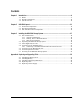
Contents Chapter 1 Introduction ..................................................................................................................................9 1.1 1.2 1.3 Chapter 2 DSN-2100 Layout .......................................................................................................................11 2.1 2.2 2.3 Chapter 3 Model .............................................................................................. 9 Benefits and Features ....................................
This Page Left Intentionally Blank viii Contents
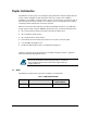
Chapter 1 Introduction The DSN-2100 storage system is an intelligent, high-performance multiple Gigabit Ethernet storage solution designed for small businesses that want to improve the reliability, availability, serviceability, and performance of their storage systems. It provides a range of benefits and features from its ability to use familiar, proven, and widespread networking technologies like IP and Ethernet for storage solutions.
1.2 1.
Chapter 2 DSN-2100 Layout This chapter describes the hardware components on the DSN-2100 storage system. The topics covered in this chapter are: Section 2.1, Front Panel Components Section 2.2, Rear Panel Components Section 2.
2.1 Front Panel Components The front of the DSN-2100 storage system has the following components: Power LED – shows the DSN-2100 power on status. (see Figure 2-1 and Table 2-1) Boot and Fault LED – shows whether the DSN-2100 is ready for operation or encountered a fault condition. (see Figure 2-1 and Table 2-1) A lock on the bezel that protects access to the drives inside the unit. The hard drive power and drive activity/fault LEDs.
Table 2-1. Front Panel LEDs LED Power Color Description Green ON = DSN-2100 is powered on. OFF = power is not being received. Boot and Fault OFF Array is powered off or performing its Power On Self Test. Red ON = a fault has occurred. Green ON = normal operation. Table 2-2. Hard Drive LEDs (for each drive 0 through 7) LED 2.1.1 Color Description Drive Power Blue ON Drive is powered and operational.
2.2 Rear Panel Components The rear of the DSN-2100 storage system enclosure has the following components: Four 1 GbE RJ-45 iSCSI host network data ports. Each iSCSI data port has port speed and port activity LEDs. (see Figure 2-2, Figure 2-3 and Table 2-4) Diagnostic port (Diagnostic Port) - one 9600 bps RS-232-C DB9 diagnostic port is located to the right of the iSCSI data ports. This requires a female-to-female straight-through cable provided with the system.
Figure 2-3 Close-Up View of the DSN-2100 Rear Panel Figure 2-4 Power and Reset Switches Table 2-3 Rear Panel Switches Switch Description Power Applies power to the DSN-2100 storage system. Pressing this switch for longer than 3 seconds removes power from the DSN-2100 storage system and turns it off. Reset Resets the DSN-2100 storage system.
Table 2-4. Data Port Speed and Port Activity LEDs LED Port Speed Color Yellow Description ON = link is operating at 1 Gbps. OFF = link is operating at either 10 Mbps or 100 Mbps. Port Activity Green ON = link is operational. Blink = data is being sent or received. Table 2-5. RJ-45 Port Activity LEDs for the Fast Ethernet Management Port Color 2.3 Description Green ON Link is operational. Green Blinking Data is being transmitted or received on the RJ-45 port.
Chapter 3 Installing the DSN-2100 Storage System This chapter describes how to install the DSN-2100 storage system. The topics covered in this chapter are: Section 3.1, Site Considerations Section 3.2, Unpacking the DSN-2100 Storage System Section 3.3, Items Supplied by the User Section 3.4, Connecting to the iSCSI Data Ports Section 3.5, Connecting to the Management Port Section 3.6, Connecting the Power Cords Section 3.
3.1 Site Considerations The site where you install the DSN-2100 storage system can affect its performance. Therefore, choose a site that conforms to the requirements in the following sections. 3.1.1 General Considerations Observe the following considerations when selecting a location to install the DSN-2100 storage system. 3.1.2 The location should be fairly cool and dry for the acceptable temperature and humidity ranges.
3.1.3 Rack-mount Guidelines The DSN-2100 storage system can be mounted in a standard 19-inch rack. Observe the following considerations for rack installations. For information about installing the system in a rack, refer to the documentation for the rack. 3.2 All rack-mounting hardware must be carefully assembled to properly support the equipment. Follow the instructions in the documentation for the rack.
3.3 Items Supplied by the User Table 3-1 lists the additional items you must supply to perform the DSN-2100 storage system installation. All users must provide the items in the first row of Table 3-1. Thereafter, the additional items required for installation depend on the user category into which you fit. Table 3-1.
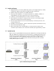
3.4 Connecting to the iSCSI Data Ports The following sections describe how to connect the DSN-2100 data ports. 3.4.1 Connecting to the DSN-2100 Host Network Connection Ports The DSN-2100 storage system has four RJ-45 data ports. These ports connect to your SAN using either a straight-through or cross-over RJ-45 Ethernet cable (the DSN-2100 storage system auto-senses the type of cable used). One cable is needed for each RJ-45 data port. 1.
3.6 Connecting the Power Cords The DSN-2100 storage system has a two power receptacles. Both must be used to connect the DSN-2100 to an AC outlet: 1. Plug the female end of the power cord into the 3-pronged power connectors on the back of the DSN-2100 storage system. Plug the other end of the power cord into a working AC outlet that is not controlled by a wall switch. 2. Repeat the previous step using the second power cable and power receptacle on the DSN-2100 storage system.
Appendix A Replacing and Upgrading FRUs This appendix describes how to replace or upgrade the Field Replaceable Units (FRUs) in your xStack Storage Array. FRUs that can be replaced or upgraded include: A.1 Battery Pack System and buffer memory SATA drives Fans Power supplies Installing the Battery Pack The xStack Storage Array accommodates a 4-cell or 6-cell shrink-wrapped battery pack.
2. Press the battery down firmly as shown in Figure A-2 until you feel it lock into place. Figure A-2 Press the Battery Down Firmly Until it Locks 3. Align the battery plug with connector J35 as shown in Figure A-3 and insert it fully into the socket.
4. The connector locked firmly into connector J35. Figure A-4 Battery Plug Locked in Place 5. The installed battery is shown in Figure A-5.
A.2 Installing Memory The xStack Storage Array provides four memory sockets: Two sockets (J36 and J37) are for buffer/cache memory Two sockets (J38 and J39) are for system memory System Memory: The xStack Storage controller can address up to 2GB of system memory, but only 512MB are required for operation of your controller. Your controller will have come standard with at least 512MB (2 x 256MB modules) making upgrading of system memory not necessary. Please see Figure A-6 system memory location.
Table A-1. xStack Storage Array DIMM Specifications Requirement Description PC2700/DDR333 speed SDRAMs must be JEDEC compliant and DDR333 capable, with a CAS latency of 2.5. PC2100/DDR400 speed DIMMs can be used if they support a 2.5 CAS latency when operating at DDR333 speed. ECC DIMMs must be organized as x72 bits wide, allowing support for ECC. X8 RAMs DIMMs must use 8-bit wide DRAMs that can support data mask (DM) signals.
A.3 Installing or Replacing SATA Drives Removal of a populated drive/tray assembly can have unforeseen effects including the loss of all data in a volume. A drive can be part of a volume that may or may not be redundant. Before removing a drive from an operating xStack Storage Array, make sure it is the correct one. A.3.
A.3.2 Installing a Hard Drive in a Drive Tray Follow these steps to install a hard drive in a drive tray. 1. Remove the plastic air dam from the tray by squeezing the two levers together and lifting the piece out of the tray as shown in Figure A-9. Figure A-9 Removing the Plastic Air Dam Piece 2. Your tray should now look like Figure A-10.
3. Place new hard drive in tray as shown in Figure A-11. Figure A-11 Place Hard Drive in Tray 4. Align the mounting holes and insert four mounting screws to hold the drive securely in the drive tray as shown in Figure A-12.
5. Your hard drive is ready for installation. Proceed to A.3.3. A.3.3 Drive and Tray Installation A drive/tray assembly can be installed by inserting the drive/tray assembly into the open drive bay as shown in Figure A-13. Push the tray at the point indicated in Step 2 of Figure A-14 and push until it is seated firmly within the bay. As you press, you will see the tray handle begin to move inwards as the locking mechanism enters the locking slot.
Figure A-14 Press Here Until You See the Lever Move Inwards Figure A-15 Press Lever Inwards Until it Locks 32 Appendix A Replacing and Upgrading FRUs
A.4 Replacing a Fan The xStack Storage Array contains three user replaceable fans. They can be replaced as follows. 1. Locate the failed fan. They can be identified by their green handle as seen in Figure A16. Figure A-16 A User Replaceable Fan with Green Handle 2. Lift the handle, grasp it and pull the fan upwards as seen in Figure A-17.
3. Remove the fan from its socket as seen in Figure A-18. Figure A-18 Remove the Fan 4. Insert the new fan by reversing the previous steps. i.e. Insert fan into socket, press firmly downwards until it is seated and lower the handle to lock it in place.
A.5 Replacing a Power Supply The xStack Storage Array contains three user replaceable power supply modules. They can be replaced as follows. 1. Locate the failed power supply module. Unscrew the bolt holding the locking mechanism in place as shown in Figure A-19. Figure A-19 Unscrew the Bolt Holding the Locking Mechanism 2. Push the locking lever to the left and pull on the handle as shown in Figure A-20. Figure A-20 Push the Locking Lever to the Left and Pull Handle 3.
Figure A-21 Remove the Power Supply Module 4. Insert the new power supply module by reversing the previous steps. i.e. Insert the new power supply module into the bay until it seats against the rear and the lever locks. Then screw the locking bolt into place.