DVA-G3340S High-Speed 2.4 GHz Wireless ADSL VOIP Router Manual Building Networks for People Ver 1.
Contents Using the Configuration Menu ................................................................10 PPPoE and PPPoA Connection for WAN........................................12 Dynamic IP Address Connection for WAN ......................................16 Bridged Connection for WAN ..........................................................19 Static IP Address for Connection WAN ...........................................21 ATM Traffic Shaping.............................................................
Bridge Filters ...................................................................................52 LAN Clients .....................................................................................53 To add a static IP address to the list of available IP addresses, type an IP address that falls within the range a available IP addresses and click on the Add button. In the example above, available addresses range from 10.0.0.1 to 10.255.255.254.
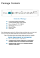
Package Contents Contents of Package: D-Link DVA-G3340S High-Speed 2.4GHz Wireless ADSL VOIP Router Power Adapter-AC 12V, 1200mA Manual and Warranty on CD RJ-11 Cable Ethernet Cable USB Cable Note: Using a power supply with a different voltage rating than the one included with the DVA-G3340S will cause damage and void the warranty for this product. If any of the above items are missing, please contact your reseller.
Introduction The D-Link DVA-G3340S High-Speed Wireless Router is an 802.11g high-performance, wireless router that supports high-speed wireless networking at home, at work or in public places. Unlike most routers, the DVA-G3340S provides data transfers at up to 8X (compared to the standard 11 Mbps) when used with other D-Link AirPlus G products. The 802.11 g standard is backwards compatible with 802.11 b products. This means that you do not need to change your entire network to maintain connectivity.
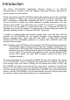
Connections This is where your Wireless LAN antenna connects. ADSL port provides a connection to your ISP and the WAN (Internet). FXS1 and FXS2 ports provide connections to two analog (POTS) telephones. USB port allows you to connect a PC to the DVA-G3304S using the supplied USB driver software and a USB port on the PC. The 12V 1.2A AC power adapter plugs in here. Line port provides a connection to your regular telephone line from the wall outlet.
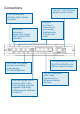
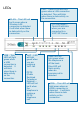
LEDs WLAN − This LED will be lit green when a Wireless LAN connection is detected. It will blink when there is data activity on the connection. USB − This LED will light green when a USB connection is detected. It will blink when there is data activity on the connection. VoIP − LED will light green when you are making a VoIP call. PSTN (Public Switched Telephone Network) − LED will not be lit when the telephone is making a PSTN telephone call.
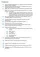
Features Fully compatible with the 802.11 g standard to provide a wireless data rate of up to 54Mbps Backwards compatible with the 802.
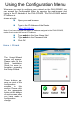
Using the Configuration Menu Whenever you want to configure your network or the DVA-G3340S, you can access the Configuration Menu by opening the web-browser and typing in the IP Address of the DVA-G3340S. The DVA-G3340S default IP Address is shown at right: Open your web browser Type in the IP Address of the Router (http://192.168.1.1) Note: if you have changed the default IP Address assigned to the DVA-G3340S, make sure to enter the correct IP Address.
Home > WAN > PPPoE/PPPoA Configure WAN Connection To configure the Router’s basic configuration settings without running the Setup Wizard, you can access the menus used to configure WAN, LAN, DHCP and DNS settings directly from the Home directory. To access the WAN Settings menu, click on the WAN link button on the left side of the first window that appears when you successfully access the web manager.
PPPoE and PPPoA Connection for WAN Follow the instructions below to configure the Router to use a PPPoE or PPPoA for the Internet connection. Make sure you have all the necessary information before you configure the WAN connection. 1. If not already selected, choose the PPPoE/PPPoA option from the WAN Settings pull-down menu. PPPoE/PPPoA is selected by default if you are configuring the Router for the first time. 2.
you will not be able to use the features configured in the Firewall and Filters menus located in the Advanced directory. See the next chapter for more details on these menus. 10.Typically the globally IP settings (i.e. IP address for the WAN interface) for a PPPoA or PPPoA connection will use Dynamic IP assignment from the ISP. Some accounts may be assigned a specific global IP address.
MTU The Maximum Transmission Unit size may be changed if you want to optimize efficiency for uploading data through the WAN interface. The default setting (1400 bytes) should be suitable for most users. Some user may want to adjust the setting to optimize performance for wireless traffic or when low latency is desired (such as with Internet gaming). It is highly recommended that the user research how adjusting the MTU may effect network traffic for better or worse.
selected in the IP Control menu, you need to type in the global IP address provided to you by your ISP. The IP Unnumbered option is used if you want to set up a non-TCP/IP port protocol link through the WAN interface. An IP Unnumbered interface does not have an IP address and therefore cannot be managed via Telnet or any other TCP/IP application. Static IP If you have selected the Static IP option in the IP Control menu, type in the global IP address used for your WAN interface.
Dynamic IP Address Connection for WAN Home > WAN > Dynamic IP Address A Dynamic IP Address connection configures the Router to automatically obtain its global IP address from a DHCP server on the ISP’s network. The service provider assigns a global IP address from a pool of addresses available to the service provider. Typically the IP address assigned has a long lease time, so it will likely be the same address each time the Router requests an IP address.
4. Some ISPs record the unique MAC address of your computer’s Ethernet adapter when you first access their network. This can prevent the Router (which has a different MAC address) from being allowed access to the ISPs network (and the Internet). To clone the MAC address of your computer’s Ethernet adapter, type in the MAC address in the Cloned MAC Address field and click the Clone MAC Address button. 5.
DHCP. Some ISPs record the unique MAC address of your computer’s Ethernet adapter when you first access their network. If you want to later replace the cloned MAC address with the factory default setting, type in all zeros - 0:0:0:0:0:0 - and click the Clone MAC Address button. MTU The Maximum Transmission Unit size may be changed if you want to optimize efficiency for uploading data through the WAN interface. The default setting (1400 bytes) should be suitable for most users.
Bridged Connection for WAN Home > WAN > Dynamic IP Address For Bridged connections it will be necessary for most users to install additional software on any computer that will the Router for Internet access. The additional software is used for the purpose of identifying and verifying your account, and then granting Internet access to the computer requesting the connection. The connection software requires the user to enter the User Name and Password for the ISP account.
method used for your ADSL service. The available options are 1483 Bridged IP LLC and 1483 Bridged IP VC-Mux. If have not been provided specific information for the Connection Type setting, leave the default setting. 4. Most users will not need to change ATM settings. If this is the first time you are setting up the ADSL connection it is recommended that you leave the Service Category settings at the default values until you have established the connection.
Static IP Address for Connection WAN Home > WAN > Static IP Address When the Router is configured to use Static IP Address assignment for the WAN connection, you must manually assign a global IP Address, Subnet Mask and Gateway IP Address used for the WAN connection. Most users will also need to configure DNS server IP settings in the DNS Settings configuration menu (see below). Follow the instruction below to configure the Router to use Static IP Address assignment for the WAN connection.
VC-MUX or IPoA. IP Address This is the permanent global IP address for your account. This is the address that is visible outside your private network. Get this from your ISP. Subnet Mask This is the Subnet mask for the WAN interface. Get this from your ISP. Gateway Address This is the IP address of your ISP’s Gateway router. It provides the connection to the Router for IP routed traffic that is outside your ISP’s network.
Firewall Use this to universally enable or disable the Firewall and Filter features available in the Router. If you disable this you will not be able to configure settings in the Firewall or Filters menus in the Advanced directory. ATM Traffic Shaping Home > WAN The ATM settings in the WAN configuration menus for the different connection types can be used to adjust QoS parameters for ADSL clients. This may not be available to all ADSL accounts.
defined. UBR – Unspecified Bit Rate, this is the default category used for general-purpose Internet traffic where normal levels of packet loss and delay are acceptable. For some applications or for multiple connection accounts, it may be desirable to specify the PCR. CBR – Constant Bit Rate, usually used in circumstances where very low packet loss and very low Cell Delay Variable (CDV) are desirable.
ATM Traffic Shaping Home > WAN The ATM settings in the WAN configuration menus for the different connection types can be used to adjust QoS parameters for ADSL clients. This may not be available to all ADSL accounts. Ask your ISP if ATM Traffic Shaping is available for your account. ATM VC Settings in WAN connection menu The table below describes the ATM VC settings used to configure a connection for an ADSL account.
disabled. WAN Setting Use this to change the type of connection used. The options are: PPPoE/PPPoA, Dynamic IP Address, Static IP Address and Bridge Mode. Each option will offer a different settings for configuration.
LAN IP Settings Home > LAN You can configure the LAN IP address to suit your preference. Many users will find it convenient to use the default settings together with DHCP service to manage the IP settings for their private network. The IP address of the Router is the base address used for DHCP. In order to use the Router for DHCP on your LAN, the IP address pool used for DHCP must be compatible with the IP address of the Router.
DHCP Settings Home > DHCP The DHCP server is enabled by default for the Router’s Ethernet LAN interface. DHCP service will supply IP settings to workstations configured to automatically obtain IP settings that are connected to the Router though an Ethernet port. When the Router is used for DHCP it becomes the default gateway for DHCP client connected to it. Keep in mind that if you change the IP address of the Router the range of IP addresses in the pool used for DHCP on the LAN will also be changed.
The two options for DHCP service are as follows: You may use the Router as a DHCP server for your LAN. You can disable DHCP service and manually configure IP settings for your workstations. You may also configure DNS settings for the LAN when using the Router in DHCP mode. In Auto DNS Mode, the Router will automatically relay DNS settings to properly configured DHCP clients.
Disable the DHCP Server To disable DHCP, click to select the No DHCP option and click on the Apply button. Choosing this option requires that workstations on the local network must be configured manually or use another DHCP server to obtain IP settings. If you configure IP settings manually, make sure to use IP addresses in the subnet of the Router. You will need to use the Router’s IP address as the Default Gateway for the workstation in order to provide Internet access.
DNS Settings Home > DNS The Router can be configured to relay DNS settings from your ISP or another available service to workstations on your LAN. When using DNS relay, the Router will accept DNS requests from hosts on the LAN and forward them to the ISP’s, or alternative DNS servers. DNS relay can use auto discovery or the DNS IP address can be manually entered by the user. Alternatively, you may also disable the DNS relay and configure hosts on your LAN to use DNS servers directly.
Dynamic DNS Settings Home > Dynamic DNS The Router supports DDNS, a service that maps Internet domain names to IP addresses. DDNS serves a similar purpose to DNS in that DDNS allows anyone hosting a Web or FTP server to advertise a public name to prospective users. Unlike DNS that only works with static IP addresses, DDNS works with dynamic IP addresses, such as those assigned by an ISP or other DHCP server.
VOIP Settings − Server Home > Voice > Server The Router can be configured to handle voice signals over the Internet Protocol (Voice Over IP − VOIP). Configure VOIP Server Settings The table below describes the VOIP Server settings. VOIP Server Parameters Description Server Address Enter the IP address of the SIP Server in this field. Server Port Enter the SIP server’s listening port for the SIP in this field.
service provider did not give you a server port number for SIP. Service Domain URL Scheme User Parameter Initial Unregister Register Expires Session Expires Min-SE Session Expires Refresher Enter the SIP service domain name in this field. Select SIP-URL to have the router include the domain name with the SIP number in the SIP messages that it sends. Select TEL-URL to have the router use the SIP number without a domain name in the SIP messages that it send. You can set this to phone or none.
VOIP Settings − User Agent Home > Voice > User Agent The Router can be configured to handle voice signals over the Internet Protocol (Voice Over IP − VOIP). Configure VOIP User Agent Settings The table below describes the VOIP Server settings. VOIP User Agent Parameters Description Same Phone Number Line Use this field to Enable or Disable the use of the same telephone number for the User Agent as for the Server Agent.
User Agent Port Authentication Username Authentication Password Confirm Password This selects the port number the router will listen to when determining when calls are being made. The Username used to access your SIP server and your VoIP service provider. The Password used to access your SIP server and your VoIP service provider. Retype your password to confirm.
OOB DTMF Inter-Digit Timer “silent Packets” when you are not speaking. Out-of band Dual Tone Multi-frequency – The Dual Tone Multi-frequency (DTMF) mode sets how the router will handle the tones that your telephone makes when you push its buttons. It is recommended that you use the same mode that your VoIP service provider uses. Select Enabled (RFC 2833) to send the DTMF tones in RTP packets. Select Disabled (G.711) to include the DTMF tones in the voice date stream.
Wireless Settings Home > Wireless The two essential settings for wireless LAN operation are the SSID and Channel Number. The SSID (Service Set Identifier) is used to identify a group of wireless LAN components. The SSID can be broadcast or can be hidden (not broadcast). Use the Wireless Settings menu to configure these basic settings. Wireless security using encryption (WEP) or access limitation (WPA) are also configured with the Wireless Settings method.
Wireless Settings − WEP Home > Wireless > WEP The wireless LAN interface of the DVA-G3340S has various security features used to limit access to the device or to encrypt data and shared information. The available standardized security for wireless LAN includes WEP and WPA Wireless security is configured with the Wireless Settings menu located in the Home directory. Wireless Security − WEP Security Options for Wireless In the Wireless Settings menu, select the type of security you want to configure.
transmitter have the correct key. WEP is disabled by default. To enable WEP, select the Enable option. Configure the Encryption Keys as desired and click the Apply button. The encryption key setup is described below. WEP can use open or shared keys, or may be configured to allow the clients to use either type of key. Use the Authentication Type: drop-down menu to choose Open, Shared or Both. • Select Open to allow any wireless station to associate with each other through the access point.
Wireless Settings − WPA Home > Wireless > WPA WPA security for wireless communication has been developed to overcome some of the shortcomings of WEP. WPA uses an improved encryption method combined with an authentication procedure. Wireless Security − WPA Configure WPA Settings To configure WPA settings, select the WPA option. The menu will change to offer the appropriate settings. WPA can be configured to work with 802.1x network authentication, or to use a PSK Hex or PSK String key.
3. Change the Port: if necessary, type in the password in the shared Secret field and change the Group Key Interval as desired. 4. Click the Apply button to put the changes into effect. Remember to save the settings using the System Settings menu. Wireless Settings − WPA-PSK Home > Wireless > WPA > PSK WPA-PSK requires a shared key but does not use a separate server for authentication. PSK keys can be ASCII or Hex type.
Multiple Virtual Connections Home > WAN > ATM VC Setting The Router supports multiple virtual connections. Up to eight PVCs to eight separate destinations can be created and operated simultaneously utilizing the same bandwidth. Additional PVC connections can be added for various purposes. For example, you may want to establish a private connection to remote office in order to create an extended LAN, or setup a server on a separate connection.
Advanced Router Management Advanced > UPnP This chapter introduces and describes the management features that have not been presented in the previous chapter. These include the more advanced features used for network management and security as well as administrative tools to manage the Router, view statistics and other information used to examine performance and for troubleshooting.
PPP, ADSL, ATM VCC, Wireless Management and Wireless Performance menus. Tools Click the Tools tab to access the Administrator Settings (used to set the system user name and password, backup and load settings), System Time Configuration, Firmware Upgrade, Diagnostic Test and Save & Reboot menus. Status Click the Status tab to view the Device Information, DHCP Clients, Event Log, Traffic Statistics and ADSL Status information windows.
UPnP Advanced > UPnP UPnP supports zero-configuration networking and automatic discovery for many types of networked devices. When enabled, it allows other devices that support UPnP to dynamically join a network, obtain an IP address, convey its capabilities, and learn about the presence and capabilities of other devices. DHCP and DNS service can also be used if available on the network.
Virtual Server Advanced > Virtual Server Use the Virtual Server menu to set up port forwarding rules in the Router. The Virtual Server function allows remote users to access services on your LAN such as FTP for file transfers or SMTP and POP3 for e-mail. The DVA-G3340S will accept remote requests for these services at your Global IP Address, using the specified TCP or UDP protocol and port number, and then redirect these requests to the server on your LAN with the Private IP address you specify.
To modify virtual server settings for any previously created rule, click on the note pad icon in the right hand column of the list for the set you want to configure. The parameters that have been configured for the rule appear in the settings fields above the list. Adjust the settings as desired and click the Apply button to put them into effect. To delete a rule from the list, click on the trash can icon and confirm that you want to delete the rule in the pop-up dialog box that appears.
Port Map This is the local port being forwarded to from the Port Start/Port End port(s). Keep in mind that if you use a non-standard port number for an application with a reserved UDP/TCP port, some additional configuration may be required for the servers or workstations using the application on the LAN side. Click the Apply button to put the new virtual server configuration set or modification into effect.
IP Filters Advanced > Filters Filter rules in the Router are put in place to allow or block specified traffic. The Filter Rules however can be used in a single direction to examine and then Allow or Deny traffic for Inbound (WAN to LAN) or Outbound (LAN to WAN) routed data. The rules based on IP address and TCP/UDP port. Configure the filter rules as desired and click the Apply button to create the rule. The newly created rule appears listed in the Outbound Filter List at the bottom of the menu.
opt to indicate a Mask Range, a Single IP, an IP Range or Any IP from the pull-down menu. Source Port The Source Port is the TCP/UDP port on either the LAN or WAN depending on if you are configuring an Outbound or Inbound Filter rule. Select one of the following options from the pull-down menu to define a Any Port, Single Port, Port Range or Safe Range (ports above 1024).
Bridge Filters Advanced > Bridge Filters Bridge filters are used to block or allow various types of packets through the WAN interface. This may be done for security or to improve network efficiency. The rules are configured for individual devices based on MAC address. Filter rules can be set up for source, destination or both. You can set up filter rules and disable the entire set of rules without loosing the rules that have been configured.
LAN Clients Advanced > Lan Clients The LAN Clients menu is used when establishing Port Forwarding, Access Control and Advanced Security rules for IP addresses on the LAN. This menu can be accessed directly by clicking on the LAN Clients button or hyperlink in the Advanced setup menu. You can also click on the New IP button located in the Port Forwarding, Access Control and Advanced Security menus to access this menu.
Routing Advanced > Routing Use Static Routing to specify a route used for data traffic within your Ethernet LAN or to route data on the WAN. This is used to specify that all packets destined for a particular network or subnet use a predetermined gateway. Static Routing menu To add a static route to a specific destination IP on the local network, enter a Destination IP address, Netmask, then click the Gateway radio button and type in the Gateway’s IP address.
DMZ Advanced > DMZ Since some applications are not compatible with NAT, the Router supports use of a DMZ IP address for a single host on the LAN. This IP address is not protected by NAT and will therefore be visible to agents on the Internet with the right type of software. Keep in mind that any client PC in the DMZ will be exposed to various types of security risks.
Firewall Advanced > Firewall The Firewall Configuration menu allows the Router to enforce specific predefined policies intended to protect against certain common types of attacks. There are two general types of protection (DoS, Port Scan) that can be enabled on the Router, as well as filtering for specific packet types sometimes used by hackers. You can choose to Enable or Disable protection against a customized basket of attack and scan types.
Null Scan attack DNS from WAN SYN/RST attack IKE from WAN SYN/FIN Scan RIP from WAN DHCP from WAN A DoS "denial-of-service" attack is characterized by an explicit attempt by attackers to prevent legitimate users of a service from using that service.
tables from other devices. Select Both to share routing tables in both directions. PPP Connection State Advanced > PPP When the WAN connection is configured for either PPPoA or PPPoE, you can configure the Router’s PPP session to remain on all the time, or to disconnect after some period of no activity. You may also choose to instruct the Router to connect each time you want to access the WAN or the Internet.
ADSL Advanced > ADSL The ADSL Configuration page allows the user to set the configuration for ADSL protocols. For most ADSL accounts the default settings Multi-mode will work. This configuration works with all ADSL implementations. If you have been given instructions to change the Modulation method used, select the desired option T1.413, G.dmt, or G.lite and click the Apply button.
ATM VC Setting Advanced > ATM VCC The ATM Virtual Circuit connection menu is used to configure the WAN connection. If you are using multiple PVCs, you can change the configuration of any PVC in this menu. To create new or additional PVCs, read the section below on Multiple PVCs. This menu can be used as an alternative menu to configure the same settings found on the WAN menu in the Home directory.
VLAN QOS Advanced > VLAN QoS is an implementation of the IEEE 802.1p standard that allows network administrators a method of reserving bandwidth for important functions that require a large bandwidth or have a high priority, such as VoIP (voice-over Internet Protocol), web browsing applications, file server applications or video conferencing. Not only can a larger bandwidth be created, but other less critical traffic can be limited, so excessive bandwidth can be saved.
Wireless Management Advanced > Wireless Management The Wireless Management menu located in the Advanced directory is used to control MAC address access to the wireless access point and to view a list of MAC addresses that are currently associated with the access point. This menu is also be used to enable and configure use of multiple SSIDs. To use more than one SSID, WEP and WPA security must first be disabled (see below).
Configure Multiple SSID Multiple SSID cannot be used if the access point has either WPE or WPA enabled. This must first be disabled in the Wireless menu located in the Home directory. To configure multiple SSID: 1. 2. 3. 4. 5. Disable WEP or WPA in the Wireless menu of the Home directory. Click in the Enable Multiple SSID option box to select it. Enter the SSID you want to add. Click the Add button to add the SSID to the list. Click the Apply button to enable the listed SSIDs.
Tools Click the Tools tab to reveal the menu buttons for various functions located in this directory. The Administrator Settings is the first menu that appears in the Tools directory. This menu is used to change the system password used to access the web manager, to save or load Router configuration settings and to restore default settings. The functions in this and the other Tools menus are described below.
Change System Password To change the password used to access the Router web manager, click the Admin button in the Tools directory to display the Administrator Settings menu. Under the Administrator heading, type the New Password and Confirm Password to be certain you have typed it correctly. Click the Apply button to activate the new password. The System User Name remains “admin”, this cannot be changed using the web manager interface. Be sure to save the new setting.
Time Tools > Time The Router provides a number of options to maintain current date and time including SNTP. Time & Date Configuration To configure system time on the Router, select the method used to maintain time. The options available include SNTP, using your computer’s system clock (default) or set the time and date manually. If you opt to use SNTP, you must enter the SNTP server URL or IP address. Click the Apply button to set the system time.
on your computer. Click the Load button to Load Settings From Local Hard Drive. Confirm that you want to load the file when prompted and the process is completed automatically. The Router will reboot and begin operating with the configuration settings that have just been loaded. Save System Settings and Restore Defaults Restore Factory Default Settings To reset the Router to its factory default settings, click the Restore button in the Administrator Settings menu.
Remote Log Tools > Remotelog
Firmware Tools > Firmware Use the Firmware Upgrade menu to load the latest firmware for the device. Note that the device configuration settings may return to the factory default settings, so make sure you save the configuration settings with the System Settings menu described above. Firmware Upgrade To upgrade firmware, type in the name and path of the file or click on the Browse button to search for the file. Click the Apply button to begin copying the file.
Ping Test Tools > Miscellaneous To perform a statndard Ping test for network connectivity, click the Misc. menu button in the Tools directory to view the Miscellaneous Configuration menu. Miscellaneous Configuration menu Ping Test The Ping test functions on the WAN and LAN interfaces. Type the IP address you want to check in the space provided and click the Ping button. Read the Ping test result in the space immediately below.
Test Tools >Test The Test menus are used to test connectivity of the Router. A Ping test may be done through the local or external interface to test connectivity to known IP addresses. The diagnostics feature executes a series of test of your system software and hardware connections. Use this Test menu when working with your ISP to troubleshoot problems.
Status Information Status > Device Info Use the various read-only menus to view system information and monitor performance. Device Information Display Use the Device Information window to quickly view basic current information about the LAN and WAN interfaces and device information including Firmware Version and MAC address.
Log Status > Log The system log displays chronological event log data. Use the navigation buttons to view or scroll log pages. You may also save a simple text file containing the log to your computer. Click the Save Log button and follow the prompts to save the file. Log display Click Clear Log delete the current log information.
Traffic Statistics Status > Statistics Use the Traffic Statistics window to monitor traffic on the Ethernet or ADSL Internet connection. When the Wireless Select the interface for which you want to view packet statistics and the information will appear below. Traffic Statistics information Click Refresh to view traffic information.
ADSL Status > ADSL Use the ADSL Status information and the Test page for troubleshooting the ADSL connection.
Technical Specifications Key Component Network Processor and ADSL Chipset Voice Chipset Description TI AR7VWi TI TNETV901 Product Feature Description Network Interface One ADSL port RJ-11, inner pair (pin 2,3) Standard Compliance ADSL Standards: ANSI T1.413 Issue 2 ITU G.992.1 (G.dmt) AnnexA ITU G.992.2 (G.lite) Annex A ITU G.994.1 (G.hs) ADSL2 Standards: ITU G.992.3 (G.dmt.bis) Annex A ITU G.992.4 (G.lite.bis) Annex A Line Rate ADSL2+ Standards: ITU G.992.
Dial Pulse (20pps/10pps) Ringer Equivalency Number REN=5 Line Impedance 600ohm Wireless Access Point Embedded Standard Compliance IEEE 802.11 IEEE 802.11b IEEE 802.11g Radio and Modulation Type Operating Frequency IEEE 802.11b: DQPSK, DBPSK, DSSS, and CCK IEEE 802.11g: BPSK, QPSK, 16QAM, 64QAM, OFDM 2400 ~ 2484.5MHz ISM band Channel Numbers 11 channels for United States 13 channels for European Countries 13 channels for Japan Data Rate IEEE 802.11b: 11, 5.
ARP ICMP IP Routing RIP v1 (RFC 1058), RIP v2 (RFC 1389) IP Static Routing DHCP DHCP Server (RFC2131) DHCP Client (RFC2131) DNS DNS Cache Dynamic DNS IP multicast IGMP Proxy IGMP Snooping ATM/ADSL Multiple PVC Support 8 PVCs ATM Cell format ITU-T Rec. I.361 ATM Adaptation Layer AAL5 ATM signaling ATM Forum UNI3.1/4.
Pass Through IPSec/L2TP/PPTP pass through NAT ALGs MSN MSGR FTP SIP (Video/ Audio/ White Board/ Remote Control) ICQ for File and Audio transfer NetMeeting 3/ 2.
Modem/Fax: V.21,V.25 PSTN Life-line Function Caller ID Life-line Backup Automatic fall back to PSTN in case of power failure PSTN line automatic selection (e.g.
Product Feature Description IP Address/Mask 192.168.1.1/255.255.255.