D-Link DVG-1120M VoIP Residential Gateway Manual Building Networks for People (10/08/04) Downloaded from www.Manualslib.
Contents Package Contents ................................................................................3 Introduction............................................................................................4 Connections .......................................................................................... 5 Features and Benefits ...........................................................................6 LEDs .........................................................................................
Package Contents Contents of Package: D-Link DVG-1120M VoIP Residential Gateway A/C Power Adapter CAT5-RJ-45 Ethernet Cable (Blue) RJ-11 Telephone Cord (Gray) Quick Installation Guide Note: Using a power supply with a different voltage rating than the one included with the DVG-1120M will cause damage and void the warranty for this product. If any of the above items are missing, please contact your reseller.
Introduction The D-Link DVG-1120M VoIP Station Gateway links traditional telephone networks to IP networks with conventional telephone devices such as analog phones or fax machines. The DVG-1120M includes two Foreign Exchange Subscriber (FXS) interfaces with normal RJ-11 telephone connectors that provide voice/fax communication over the IP network. Two Ethernet ports are also provided.
Connections Warning! Using a different power adapter than the one included with your purchase will damage the DVG-1120M and void the warranty. Reset Switch Used to return the device to its original configuration. This is the same as performing a factory reset. AC Power Connector Use the included power adapter. If you use a power adapter other than the one included with the product you will damage the device and void the warranty on this product. Diagnostic Port An RJ-14 port used to configure the device.
Features & Benefits One analog FXS interface port accepting an RJ-11 connector to facilitate a VoIP connection One 10Mbps WAN port for connecting to a DSL/Cable Modem or other WAN devices One 10/100Mbps LAN port for connecting to a local network IP address assignment using DHCP (Dynamic Host Configuration Protocol) or static configuration IP Routing support (RIP1, RIP2 and Static Routing) Remote software download/update Supports IP sharing to allow multiple users to access the Internet via a single IP addre
LEDS Power This LED is lit when the device is receiving power; otherwise, it is unlit. Status/Alarm This LED will remain green when the CPE is either performing a self-test or booting up. The LED will flash green slowly when the system is ready for a connection with the Call Agent. It will remain red when the self-test or booting up is failed. It will flash red slowly when the system is ready but cannot receive an acknowledgment from the Call Agent.
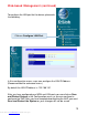
Web-based Management In order to use a web browser to configure the VoIP gateway, you must make sure it has a valid Ethernet connection to a PC or LAN via its LAN port. Access the configuration utility to check the LAN port by entering the IP Address into your web browser address field. Type 192.168.15.1 (the IP Address) into the address field of your browser. http://192.168.15.1 Click on Login to the Web-based Management module 8 Downloaded from www.Manualslib.
Web-based Management (continued) Setting Up the Connection To configure the WAN port, please do the following: Click on Configure WAN Port. Manually input the WAN IP Address here. Then go to Start>Control Panel>Network Connections>Right-click local area connection >select Properties> double click Internet Protocol (TCP/IP). The screen at right will appear. The VoIP gateway’s WAN port comes with DHCP as default IP setting.
Web-based Management (continued) To configure the LAN port for the device, please do the following: Click on Configure LAN Port. In this configuration menu, users can configure the LAN IP Address. (Recommended for advanced users.) By default the LAN IP Address is: 192.168.15.1 After you have configured your WAN and LAN ports you can click on Save and Restart System in the Configuration menu, or you can continue to configure the VoIP.
Web-based Management (continued) Configure LAN Port > Proxy DNS State - This toggles Enable and Disable for the Proxy DNS function. Proxy DNS IP Address - Enter the Proxy DNS IP address if instructed by your service provider. Click Save to save the settings. Configure LAN Port > Bridge Mode Bridge Mode - This toggles On and Off to turn NAT on or off for Static Public IP assignment. Click Save to save the settings. 11 Downloaded from www.Manualslib.
Web-based Management (continued) Configure LAN Port > DHCP Configuration > Dynamic IP Assignment Use the Dynamic IP Assignment to configure the device to act as a DHCP server for the LAN. The items on this window are described below: Default Gateway - This specifies the Gateway IP Address that will be assigned to and used by the DHCP clients. Start IP Address -This is the base (starting) address for the IP pool of unassigned IP addresses.
Web-based Management (continued) Configure LAN Port > DHCP Configuration > Static IP Assignment The Static IP Assignment functions in much the same way as the Dynamic IP Assignment. The only difference is that a particular IP address can be assigned to a particular host. The host is identified by the MAC Address of its NIC which must be entered on next screen.
Web-based Management (continued) Configure LAN Port > NAT Configuration Select enabled or disabled for the NAT function. Click Save to save the settings. Configure LAN Port > NAT Configuration > Virtual Server Configuration This window allows you to view the current virtual server configuration settings. Click the edit icon on this window to access the second Virtual Server Configuration window: 14 Downloaded from www.Manualslib.
Web-based Management (continued) Configure LAN Port > NAT Configuration > Virtual Server Configuration (continued) The items on this window are described below: Index - Choose the index number that you would like to edit (Form 1 to 6). Protocol - Choose the protocol either TCP or UDP. Global Port Range Enter the designated TCP or UDP protocol port number for the particular protocol packet you wish to redirect.
Web-based Management (continued) Configure LAN Port > NAT Configuration > Dynamic NAT This window allows you to view the current Dynamic NAT settings. Click the edit icon on this window to access the second Dynamic NAT window: The items on this window are described below: Index - Choose the index number that you would like to edit (Form 1 to 6). Global IP Start - Enter the beginning designated IP address for the particular range of packets you wish to redirect to local addresses.
Web-based Management (continued) Configure LAN Port > NAT Configuration > Static NAT This window allows you to view the current Static NAT settings. Click the edit icon on this window to access the second Static NAT window: The items on this window are described below: Index - Choose the index number that you would like to edit (Form 1 to 6). Local IP Address - Enter the designated IP address for the packet you wish to redirect to a Global address.
Web-based Management (continued) Configure LAN Port > Routing > RIP Select to use RIPv1, RIPv2 or On (both versions) for the LAN and WAN interface. To disable both versions of RIP select Off. Click Save to save the settings. RIP - Routing Information Protocol that specifies how routers exchange information. With RIP, routers periodically exchange entire tables. Configure LAN Port > Routing > Static Route Configuration Use Static Routing to specify a route used for data traffic within your WAN or LAN.
Web-based Management (continued) Configure LAN Port > RIP > Static Route Configuration (continued) The items on this window are described below: IP Address - Type in the IP Address of the subnet or device where packets are routed. Subnet Mask - Type in an appropriate subnet mask that allows the static route to function. Gateway - Type in the IP Address of the gateway used for traffic destined for the specified subnet or device. Interface - Select WAN or LAN Interface.
Web-based Management (continued) Firewall Rules Firewall Rules is an advance feature used to deny or allow traffic from passing through the device. The filtering sets are sets of rules defined in the menus shown below. Click the edit icon on the window above to access the Firewall Rules window for the first rules set: Type in an appropriate identifying comment for the Firewall Rules set.
Web-based Management (continued) Firewall Rules (continued) Comment- Type in an appropriate identifying comment for the rule. Pass or Block- Select Pass or Block to perform this action on packets as defined below. Direction- Select In or Out to pass or block packets coming in or going out of the network. Protocol-Select IGMP, TCP, UDP or All to pass or block packets of that protocol type. Source- Type in the source IP Address and select the Subnet Mask to pass or block packets from that IP Address.
Web-based Management (continued) Firewall Rules (continued) TCP Flag - Select enabled or disabled to enable or disable the filter rule as defined in the menu. TCP Packet Options - Optional TCP packet options include: Acknowledgement, Push, Reset, SYN, and FIN. Consult a certified technician before selecting any of these advanced options. Filter Rule State - Select enabled or disabled to enable or disable the filter rule as defined in the menu. Click Save or click Clear to Save or Clear the settings.
Web-based Management (continued) MAC Filter (continued) The items on this window are described below: Index - This is the index number that you are editing (1-16). MAC Address - Enter the MAC address of the client that will be filtered. State - This toggles Disable and Enable for the MAC address filtering function for this index. Click the Save button to save the settings.
Web-based Management (continued) Statistics > WAN Internet Connection Statistics This window displays a variety of WAN Connection statistics. Statistics > Phone Port Statistics This window displays a variety of Phone Port statistics. 24 Downloaded from www.Manualslib.
Web-based Management (continued) Configuration Restore and Backup The current system settings can be saved as a file onto the local hard drive. The saved file or any other saved setting file created by the DVG-1120M can be uploaded into the unit. To restore a system settings file, click on Browse to search the local hard drive for the file to be used.
Web-based Management (continued) Factory Reset Before performing a Factory Reset, be absolutely certain that this is what you want to do. Once the reset is done, all of the device’s settings stored in NVRAM will be erased and restored to values present when the device was purchased. Click on Reset to Factory Default to reset the NV-RAM to the default values that were present when you purchased the device.
Web-based Management (continued) Save and Restart System After the settings have been saved to NV-RAM, they will become the default settings for the device, and they will be used every time it is powered on, reset or rebooted. The only exception to this is a factory reset, which will clear all settings and restore the unit’s settings back to their initial values, which were present when the device was purchased. Click on Save Configuration at the bottom of the window to save the system settings to NV-RAM.
Web-based Management (continued) About This read-only window displays information about the DVG-1120M VoIP Station Gateway such as: Device Type, MAC Address, Boot PROM Firmware, Firmware Version, and DSP Version. The DSP Version will list “Not yet loaded” until you initialize your unit. 28 Downloaded from www.Manualslib.
Technical Specifications Call Control Protocols Compliance: MGCP Voice Compression: G.711 (A-law and u-law), G.723.1, G.729a Analog Voice Ports: Type: Loop-Start FXS interfaces DTMF tone detection/generation V.21/V.25 Modem/Fax tone detection Echo Cancellation: G.165/G.168 Ethernet Ports: WAN: 10BASE-T Ethernet port (MDI-II) LAN: NWay 10/100BASE-TX Fast Ethernet ports (MDI-X) IEEE 802.3 10BASE-T Ethernet compliance IEEE 802.
Technical Specifications (continued) Network Management: SNMP management agent base MIB II Telnet provisioning Manage functions through an intuitive web-based graphical user interface TFTP: The built-in Trivial File Transfer Protocol provides firmware upgrade Security: Password Authentication Protocol/Challenge Handshake Authentication Protocol (PAP/CHAP) Administrative password through Web, Telnet and SNMP Packet filter by IP Address, port number and protocol LEDs: General: Power Status/Alarm Ethernet: WAN
Technical Specifications (continued) Power Supply: AC-to-DC power adapter (provided) DC Input: 12VDC/1A Operating Temperature: 0-50°C Storage Temperature: -10-55°C Humidity: 5% - 95% non-condensing Safety: UL/CUL Emission (EMI): FCC Class B VCCI Class B BSMI Class B CE Class B C-Tick Class B 31 Downloaded from www.Manualslib.
Techni cal Support echnical You can find software updates and user documentation on the D-Link website. D-Link provides free technical support for customers within the United States and within Canada for the duration of the warranty period on this product. U.S. and Canadian customers can contact D-Link technical support through our website, or by phone. Tech Support for customers within the United States: D-Link Technical Support over the Telephone: (877) 453-5465 24 hours a day, seven days a week.
Warranty Subject to the terms and conditions set forth herein, D-Link Systems, Inc. (“D-Link”) provides this Limited warranty for its product only to the person or entity that originally purchased the product from: D-Link or its authorized reseller or distributor and Products purchased and delivered within the fifty states of the United States, the District of Columbia, U.S. Possessions or Protectorates, U.S. Military Installations, addresses with an APO or FPO.
The original product owner must obtain a Return Material Authorization (“RMA”) number from the Authorized D-Link Service Office and, if requested, provide written proof of purchase of the product (such as a copy of the dated purchase invoice for the product) before the warranty service is provided.
Governing Law: This Limited Warranty shall be governed by the laws of the State of California. Some states do not allow exclusion or limitation of incidental or consequential damages, or limitations on how long an implied warranty lasts, so the foregoing limitations and exclusions may not apply. This limited warranty provides specific legal rights and the product owner may also have other rights which vary from state to state. Trademarks: D-Link is a registered trademark of D-Link Systems, Inc.
Registration Register online your D-Link product at http://support.dlink.com/register/ 10/08/04 36 Downloaded from www.Manualslib.