D-Link DVG-1402S Broadband Phone Service VoIP Router Manual Building Networks for People (09/24/04)
Contents Package Contents ................................................................................3 Introduction............................................................................................4 Connections ..........................................................................................5 Features and Benefits ...........................................................................6 LEDs ..........................................................................................
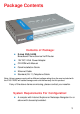
Package Contents Contents of Package: D-Link DVG-1402S Broadband Phone Service VoIP Router 12V DC/1.25A Power Adapter CD-ROM with Manual Quick Installation Guide Ethernet Cable Standard (RJ-11) Telephone Cable Note: Using a power supply with a different voltage rating than the one included with the DVG-1402S will cause damage and void the warranty for this product. If any of the above items are missing, please contact your reseller.
Introduction The D-LINK DVG-1402S Broadband Phone Service VoIP Router links traditional telephony networks to IP networks with conventional telephony devices such as analog phones or fax machines. The DVG-1402S includes two RJ-11 telephone jacks that provide voice communication over the IP network, and five Ethernet ports. One Ethernet port is for a DSL/Cable Modem or other wide area network (WAN) devices, and the others are for connections to create a home or small office local area network (LAN).
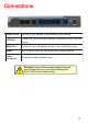
Connections Phone Ports Connect to your phones using standard phone cabling. LAN Port C o nne c t to yo ur E the rne t e na b le d c o mp ute rs us i ng E the rne t cabling. WAN Port Connects to your broadband modem using an Ethernet cable. R eset This is used to reset the unit to the factory default settings. P o w er Connector The power adapter attaches here. Warning! Using a different power adapter than the one included with your purchase will damage the DVG-1402S and void the warranty.
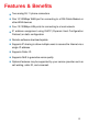
Features & Benefits Two analog RJ-11 phone connectors One 10/100Mbps WAN port for connecting to a DSL/Cable Modem or other WAN devices Four 10/100Mbps LAN ports for connecting to a local network IP address assignment using DHCP (Dynamic Host Configuration Protocol) or static configuration Remote software download/update Supports IP sharing to allow multiple users to access the Internet via a single IP address Supports Caller ID Supports QoS to guarantee voice quality Optional features may be supported by yo
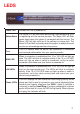
LEDS P o w er L E D Status/Alarm Indicates the unit is powered on. The Status LED will flash when performing a self-test/booting up or is registering with the service provider. The Status LED will flash green slowly when the system is connected with the service. The Alarm LED will light solid red if the self-test or bootup fails. The Alarm LED will flash red slowly when the system is ready but cannot receive an acknowledgement from the service.
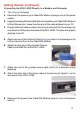
Getting Started Connecting the DVG-1402S Directly to a Modem and Computer If your computer connects directly to a DSL or Cable modem and does not connect to a router, follow the steps below to install your DVG-1402S. After the steps are completed, your setup should look similar to the diagram below. Note: This is the most common setup configuration for the DVG-1402S. If you do not require the use of more than four LAN ports, you do not need an additional router.
Getting Started (continued) Connecting the DVG-1402S Directly to a Modem and Computer 1. Turn off your Computer. 2. Disconnect the power to your Cable/DSL Modem (unplug or turn off the power switch). 3. Unplug the existing Ethernet cable that is connected to your Cable/DSL Modem’s LAN or Ethernet port. Leave the other end of this cable attached to your PC. 4. Plug the Ethernet cable connector that you just removed from the modem into one of the four LAN ports on the back of the DVG-1402S.
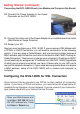
Getting Started (continued) Connecting the DVG-1402S Directly to a Modem and Computer (No Router) 10. Connect the Power Adapter to the Power Connecter on the DVG-1402S. 11. Connect the other end of the Power Adapter to an available electrical outlet (Wall Socket or Surge Protector). 12. Restart your PC. Next you must configure your DVG-1402S. If you are using a DSL Modem with a PPPoE or DHCP connection, you will need to continue on to the following section.
Getting Started (continued) Connecting the DVG-1402S Directly to a Modem and Computer (No Router) Click Login to the webbased management module. Click Configure WAN/LAN Access. Click Configure WAN Port. Select PPPoE from the pull-down menu. Enter your User Name and Authentication Password and Confirm Password. Click Save.
Getting Started (continued) Connecting the DVG-1402S Directly to a Modem and Computer (No Router) Select Save changes and reboot system now. Click Save. Once the unit reboots you will be returned to the main screen. Check to see if the status LED light is blinking green on the front panel of the DVG-1402S. Setup of the DVG-1402S with a DSL modem is now complete.
Getting Started (continued) Connecting the DVG-1402S in Front of a Router If you wish to connect your DVG-1402S in front of a router, follow the steps below. After the steps are completed, your setup should look similar to the diagram below. This is the recommended method for setting up the DVG-1402S. This set up allows the DVG-1402S to prioritize voice traffic over data traffic, thus providing you with greater consistency and call quality. 1. Turn off your Computer. 2.
Getting Started (continued) Connecting the DVG-1402S in Front of a Router 6. Plug the Cat 5 Ethernet Cable from the Cable/DSL Modem into the “WAN” port of the DVG-1402S. 7. Unpack the Cat 5 Ethernet Cable (blue) that came with the DVG-1402S. 8. Attach one end of this Cat 5 Ethernet Cable (blue) to one of the four “LAN” Ports on the rear of the DVG-1402S. 9. Attach the other end of this Cat 5 Ethernet Cable (blue) to the “WAN” port of your existing router. 10.
Getting Started (continued) Connecting the DVG-1402S in Front of a Router 17. Reconnect the power to the Cable/DSL Modem (plug in or turn on the power switch). 18. Reconnect the power to your existing Router (plug in or turn on the power switch). 19. Restart your PC. Next you must configure your DVG-1402S and PC. If you are using a DSL Modem with a PPPoE or DHCP connection, you will need to continue on to the following section.
Getting Started (continued) Connecting the DVG-1402S in Front of a Router Click Login to the webbased management module. Click Configure WAN/LAN Access. Click Configure WAN Port. Select PPPoE from the pull-down menu. Enter your User Name and Authentication Password and Confirm Password. Click Save.
Getting Started (continued) Connecting the DVG-1402S in Front of a Router Select Save changes and reboot system now. Click Save. Once the unit reboots you will be returned to the main screen. Check to see if the status LED light is blinking green on the front panel of the DVG-1402S. Setup of the DVG-1402S with a DSL modem is now complete.
Getting Started (continued) Connecting the DVG-1402S Behind a Router If you wish to connect your DVG-1402S behind a router, follow the steps below. After the steps are completed, your setup should look similar to the diagram below. 1. Turn off your Computer. 2. Disconnect the power to the Cable/DSL Modem (unplug or turn off the power switch). 3. Disconnect the power to your existing router (unplug or turn off the power switch). 4.
Getting Started (continued) Connecting the DVG-1402S Behind a Router 6. Plug the Cat 5 Ethernet Cable from the PC into the “LAN” port of the DVG-1402S. 7. Unpack the Cat 5 Ethernet Cable (blue) that came with the DVG-1402S. 8. Attach one end of this Cat 5 Ethernet Cable (blue) to the “WAN” Port on the rear of the DVG-1402S. 9. Attach the other end of this Cat 5 Ethernet Cable (blue) to the “LAN” port of your existing router. 10.
Getting Started (continued) Connecting the DVG-1402S Behind a Router 16. Connect the other end of the Power Adapter to an available electrical outlet (Wall Socket or Surge Protector). 17. Reconnect the power to the Cable/DSL Modem (plug in or turn on the power switch). 18. Reconnect the power to your existing Router (plug in or turn on the power switch). 19. Restart your PC. By default the unit is already configured to work behind a router.
MAC Cloning For Cable Connection Some cable Internet service providers require that device connected to the cable modem has the MAC address of the PC that was originally registered with the cable Internet provider. If this is required to set up the DVG-1402S, follow the steps below. 1. On the computer that was originally registered with your service provider. For Windows 98/Me users: Go to Start > Run > command. Type in ipconfig/ all. The physical address listed is your system’s MAC address.
Web-based Management Prior to using your Web browser for Web-based management, if DHCP is not enabled on your computer, be sure to assign a static IP address to the VoIP Router. Go to Start>Control Panel>Network Connections>Right-click local area connection >select Properties> double click Internet Protocol (TCP/IP). The screen at right will appear. The VoIP Router’s LAN port comes with DHCP as default IP setting.
Web-based Management (continued) Click on Login to the Web-based Management module Setting Up the Connection To configure the WAN port, please do the following: Click on Configure WAN Port. Choose your type of connection. Manually enter your DNS address (if applicable).
Web-based Management (continued) To configure the LAN port for the device, please do the following: Click on Configure LAN Port. In this configuration menu, users can configure the LAN IP Address. (Recommended for advanced users.) By default the LAN IP Address is: 192.168.15.1 After you have configured your WAN and LAN ports you can click on Save and Restart System in the Configuration menu, or you can continue to configure the VoIP Router.
Web-based Management (continued) Configure LAN Port > Proxy DNS State - This toggles Enable and Disable for the Proxy DNS function. Proxy DNS IP Address - Enter the Proxy DNS IP address if instructed by your service provider. Click Save to save the settings. Configure LAN Port > Bridge Mode Bridge Mode - This toggles On and Off to turn NAT on or off for Static Public IP assignment. Click Save to save the settings.
Web-based Management (continued) Configure LAN Port > DHCP Configuration > Dynamic IP Assignment Use the Dynamic IP Assignment to configure the device to act as a DHCP server for the LAN. The items on this window are described below: Default Gateway - This specifies the Gateway IP Address that will be assigned to and used by the DHCP clients. Start IP Address -This is the base (starting) address for the IP pool of unassigned IP addresses.
Web-based Management (continued) Configure LAN Port > DHCP Configuration > Static IP Assignment The Static IP Assignment functions in much the same way as the Dynamic IP Assignment. The only difference is that a particular IP address can be assigned to a particular host. The host is identified by the MAC Address of its NIC which must be entered on next screen.
Web-based Management (continued) Configure LAN Port > NAT Configuration Select enabled or disabled for the NAT function. Click Save to save the settings. Configure LAN Port > NAT Configuration > Virtual Server Configuration This window allows you to view the current virtual server configuration settings.
Web-based Management (continued) Configure LAN Port > NAT Configuration > Virtual Server Configuration (continued) The items on this window are described below: Index - Choose the index number that you would like to edit (Form 1 to 6). Protocol - Choose the protocol either TCP or UDP. Global Port Range Enter the designated TCP or UDP protocol port number for the particular protocol packet you wish to redirect.
Web-based Management (continued) Configure LAN Port > NAT Configuration > Virtual Server Configuration (continued) The items on this window are described below: DMZ Forwarding Mode - Select to enable or disable the DMZ. The DMZ (Demilitarized Zone) allows a single computer to be exposed to the internet. By default the DMZ is disabled. DMZ Host IP Address - Enter the IP address of the DMZ host. Click Save to save the settings.
Web-based Management (continued) Configure LAN Port > NAT Configuration > Dynamic NAT (continued) The items on this window are described below: Index - Choose the index number that you would like to edit (Form 1 to 6). Global IP Start Enter the beginning designated IP address for the particular range of packets you wish to redirect to local addresses. Global IP End - Enter the end designated IP address for the particular range of packets you wish to redirect to local addresses.
Web-based Management (continued) Configure LAN Port > NAT Configuration > Static NAT This window allows you to view the current Static NAT settings. Click the edit icon on this window to access the second Static NAT window: The items on this window are described below: Index - Choose the index number that you would like to edit (Form 1 to 6). Local IP Address - Enter the designated IP address for the packet you wish to redirect to a Global address.
Web-based Management (continued) Configure LAN Port > Routing > RIP Select to use RIPv1, RIPv2 or On (both versions) for the LAN and WAN interface. To disable both versions of RIP select Off. Click Save to save the settings. RIP - Routing Information Protocol that specifies how routers exchange information. With RIP, routers periodically exchange entire tables. Configure LAN Port > Routing > Static Route Configuration Use Static Routing to specify a route used for data traffic within your WAN or LAN.
Web-based Management (continued) Configure LAN Port > RIP > Static Route Configuration (continued) The items on this window are described below: IP Address - Type in the IP Address of the subnet or device where packets are routed. Subnet Mask - Type in an appropriate subnet mask that allows the static route to function. Gateway - Type in the IP Address of the gateway used for traffic destined for the specified subnet or device. Interface - Select WAN or LAN Interface.
Web-based Management (continued) Firewall Rules Firewall Rules is an advance feature used to deny or allow traffic from passing through the device. The filtering sets are sets of rules defined in the menus shown below. Click the edit icon on the window above to access the Firewall Rules window for the first rules set: Type in an appropriate identifying comment for the Firewall Rules set.
Web-based Management (continued) Firewall Rules (continued) Comment- Type in an appropriate identifying comment for the rule. Pass or BlockSelect Pass or Block to perform this action on packets as defined below. Direction- Select In or Out to pass or block packets coming in or going out of the network. Protocol- Select IGMP, TCP, UDP or All to pass or block packets of that protocol type. Source- Type in the source IP Address and select the Subnet Mask to pass or block packets from that IP Address.
Web-based Management (continued) Firewall Rules (continued) TCP Flag - Select enabled or disabled to enable or disable the filter rule as defined in the menu. TCP Packet Options - Optional TCP packet options include: Acknowledgment, Push, Reset, SYN, and FIN. Consult a certified technician before selecting any of these advanced options. Filter Rule State - Select enabled or disabled to enable or disable the filter rule as defined in the menu. Click Save or click Clear to Save or Clear the settings.
Web-based Management (continued) MAC Filter (continued) The items on this window are described below: Index - This is the index number that you are editing (1-16). MAC Address - Enter the MAC address of the client that will be filtered. State - This toggles Disable and Enable for the MAC address filtering function for this index. Click the Save button to save the settings.
Web-based Management (continued) Statistics > WAN Internet Connection Statistics This window displays a variety of WAN Connection statistics. Statistics > Phone Port Statistics This window displays a variety of Phone Port statistics.
Web-based Management (continued) Configuration Restore and Backup The current system settings can be saved as a file onto the local hard drive. The saved file or any other saved setting file created by the DVG-1402S can be uploaded into the unit. To restore a system settings file, click on Browse to search the local hard drive for the file to be used.
Web-based Management (continued) Factory Reset Before performing a Factory Reset, be absolutely certain that this is what you want to do. Once the reset is done, all of the device’s settings stored in NVRAM will be erased and restored to values present when the device was purchased. Click on Reset to Factory Default to reset the NV-RAM to the default values that were present when you purchased the device.
Web-based Management (continued) Save and Restart System After the settings have been saved to NV-RAM, they will become the default settings for the device, and they will be used every time it is powered on, reset or rebooted. The only exception to this is a factory reset, which will clear all settings and restore the unit’s settings back to their initial values, which were present when the device was purchased. Click on Save Configuration at the bottom of the window to save the system settings to NV-RAM.
Web-based Management (continued) About This read-only window displays information about the DVG-1402S VoIP such as: Device Type, MAC Address, Boot PROM Firmware, Firmware Version, and DSP Version. The DSP Version will list “Not yet loaded” until you initialize your unit.
Frequently Asked Questions Q: I have completed the installation of my D-Link DVG-1402S, but do not hear a dial tone. A: Be sure that the unit is properly plugged into the AC outlet, the analog phone is properly plugged into the RJ11 jack behind the unit, and the power connector is plugged in. Verify that status lights are lit/blinking. 1) Verify the Power light is on. 2) Initially the Alarm light will blink. 3) The provision (prov.) Light will also blink during the boot up.
Frequently Asked Questions (continued) port, Authentication User Name, Authentication Password, and Confirm Password. Q: After setting up the DVG-1402S, I cannot surf the internet. A: Re-check all the cabling installations. Make sure that the Ethernet cable from the PC is plugged into one of the LAN ports of the DVG-1402S and the Ethernet cable from the cable modem is plugged into the WAN port of the DVG1402S.
Frequently Asked Questions (continued) 10) Verify that the WAN port for Public IP is NOT 10.1.1.1. (It must be an IP address given by your Internet Service Provider (ISP) through the Cable or DSL modem.) Q: Can I use my DVG-1402S on a MGCP network? A: No, DVG-1402S is a SIP device and uses the SIP protocol in handling all of the telephony elements. Q: I need to open certain ports, where do I go to make this configuration change? A: This can be done in the “Firewall Rules”.
Technical Specifications Call Control Protocols Compliance: SIP2 (RFC3261) SIP1 (RFC2543) Voice Compression: G.711 (A-law and u-law), G.723.1, G.726, G.729a Analog Voice Ports: Type: Loop-Start FXS interfaces DTMF tone detection/generation V.21/V.25 Modem/Fax tone detection Echo Cancellation: G.168 Ethernet Ports: WAN/LAN: 10/100 Auto MDI/MDI-X Ethernet ports IEEE 802.3 10BASE-T Ethernet compliance IEEE 802.
Technical Specifications (continued) LEDs: General: Power Status/Alarm Ethernet: WAN: 10/100M, Link/Act LAN: 10/100M, Link/Act Phone 1 to 2: MWI Hook/Ringing Provision Light Dimensions: W = 6.77 inches (172mm) D = 6.16 inches (156.6 mm) H = 1.34 inches (34mm) Number of Ports: One 10/100BASE-T Ethernet port (WAN) Four 10/100BASE-TX Fast Ethernet port (LAN) Two loop-start FXS RJ-11 ports Power Supply: AC-to-DC power adapter (provided) DC Input: 12VDC/1.
Technical Specifications (continued) Safety: UL/CUL Emission (EMI): FCC Class B CE Class B 49
For Technical Support regarding your phone service, please contact the service provider. If you experience any hardware problems with the DVG-1402S, please contact D-Link Technical Support. Techni cal Support echnical You can find software updates and user documentation on the D-Link website. D-Link provides free technical support for customers within the United States and within Canada for the duration of the warranty period on this product. U.S.
Warranty and Registration Subject to the terms and conditions set forth herein, D-Link Systems, Inc. (“D-Link”) provides this Limited warranty for its product only to the person or entity that originally purchased the product from: D-Link or its authorized reseller or distributor and Products purchased and delivered within the fifty states of the United States, the District of Columbia, U.S. Possessions or Protectorates, U.S. Military Installations, addresses with an APO or FPO.
The original product owner must obtain a Return Material Authorization (“RMA”) number from the Authorized D-Link Service Office and, if requested, provide written proof of purchase of the product (such as a copy of the dated purchase invoice for the product) before the warranty service is provided.
Governing Law: This Limited Warranty shall be governed by the laws of the State of California. Some states do not allow exclusion or limitation of incidental or consequential damages, or limitations on how long an implied warranty lasts, so the foregoing limitations and exclusions may not apply. This limited warranty provides specific legal rights and the product owner may also have other rights which vary from state to state. Trademarks: D-Link is a registered trademark of D-Link Systems, Inc.