D-Link AirPlus Xtreme G DWL-2100AP 802.11g Wireless 108Mbps Access Point Manual V2.
Contents Package Contents ................................................................................ 3 Introduction ........................................................................................... 4 Connections ......................................................................................... 5 Features and Benefits .......................................................................... 7 Wireless Basics ..............................................................................
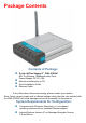
Package Contents Contents of Package: D-Link AirPlus Xtreme G ® DWL-2100AP 802.11g Wireless 108Mbps Access Point Power Adapter-DC 5V, 2.0A Manual and Warranty on CD Quick Installation Guide Ethernet Cable If any of the above items are missing, please contact your reseller. Note: Using a power supply with a different voltage rating than the one included with the DWL-2100AP will cause damage and void the warranty for this product.
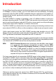
Introduction At up to fifteen times the maximum wireless signal rate of previous wireless devices (up to 108Mbps* in Super G mode), you can work faster and more efficiently, increasing productivity. With the DWL-2100AP, bandwidth-intensive applications like graphics or multimedia will benefit significantly because large files are able to move across the network quickly. The DWL-2100AP is capable of operating in one of 5 different modes to meet your wireless networking needs.
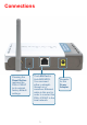
Connections Pressing the Reset Button restores the DWL-2100AP to its original factory default settings. The LAN Port is Auto-MDI/MDIX. You can insert either a straightthrough or a crossover Ethernet cable in this port in order to connect the DWL-2100AP to the local network. 5 Receptor for the Power Adapter.
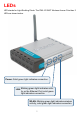
LEDs LED stands for Light-Emitting Diode. The DWL-2100AP Wireless Access Point has 3 LEDs as shown below: Power: Solid green light indicates connection. LAN: Blinking green light indicates activity on the Ethernet Port; solid green light indicates connection. WLAN: Blinking green light indicates wireless activity; solid green light indicates connection.
Features 5 Different Operation modes - Capable of operating in one of five different operation modes to meet your wireless networking requirements: Access Point, AP-to-multipoint bridge with AP function, AP-to-Multipoint Bridging without AP function , Repeater, or Wireless Client. Faster wireless networking with the 802.11g standard to provide a wireless data rate of up to 54Mbps (108Mbps in Super G mode). Compatible with the 802.
Wireless Basics D-Link wireless products are based on industry standards to provide easy-to-use and compatible high-speed wireless connectivity within your home, business or public access wireless networks. D-Link wireless products will allow you access to the data you want, when and where you want it. You will be able to enjoy the freedom that wireless networking brings. A Wireless Local Area Network (WLAN) is a computer network that transmits and receives data with radio signals instead of wires.
Wireless Basics (continued) The DWL-2100AP is compatible, in default mode, with the following wireless products: D-Link AirPlus Xtreme G TM DWL-G650 Wireless Cardbus Adapters used with laptop computers D-Link AirPlus Xtreme G DWL-G520 TM Wireless PCI cards used with desktop computers The DWL-2100AP is also interoperable with other 802.11g and 802.11b standards-compliant devices. Standards-Based Technology The DWL-2100AP Wireless Access Point utilizes the 802.11b and the 802.11g standards.
Wireless Basics (continued) Installation Considerations The D-Link AirPlus Xtreme GTM DWL-2100AP lets you access your network, using a wireless connection, from virtually anywhere within its operating range. Keep in mind, however, that the number, thickness and location of walls, ceilings, or other objects that the wireless signals must pass through, may limit the range. Typical ranges vary depending on the types of materials and background RF (radio frequency) noise in your home or business.
Getting Started On the following pages we will show you an example of an Infrastructure Network incorporating the DWL-2100AP. An Infrastructure network contains an access point or a wireless router.
Getting Started (continued) 1 2 Setting up a Wireless Infrastructure Network 3 4 5 6 Please remember that D-Link AirPlus Xtreme G wireless devices are pre-configured to connect together, right out of the box, with their default settings. TM For a typical wireless setup at home (as shown above), please do the following: You will need broadband Internet access (a Cable or DSL-subscriber line into your home or office). Consult with your Cable or DSL provider for proper installation of the modem.
Using the Configuration Menu After you have completed the Setup Wizard (please see the Quick Installation Guide that came with the product) you can access the Configuration menu at any time by opening the Web browser and typing in the IP address of the DWL-2100AP. The DWL-2100AP default IP address is shown below: Open the Web browser Type in the IP address of the DWL-2100AP Note: if you have changed the default IP address assigned to the DWL-2100AP, make sure to enter the correct IP address.
Using the Configuration Menu (continued) Home > Wireless >AP Mode Wireless Band- IEEE 802.11g. Mode Access Point is selected from the pull down menu.. SSID Service Set Identifier(SSID)is the name designated for a specific wireless local area network(WLAN).The SSID factpru default setting is default.The SSID can be easily changed to connect to an existing network or to establish a new wireless network. SSID Broadcast- Enable or Disable SSID Broadcast.
Using the Configuration Menu (continued) Home > Wireless>AP Mode(continued) Authentication: Open System Shared Key Open System/Shared Key WPA-EAP WPA-PSK Select Open System to communicate the key across the network. Select Shared Key to limit communication to only those devices that share the same WEP settings. Select Open System/Shared Key to allow either form of data encryption. Select WPA-EAP to secure your network with the inclusion of a RADIUS server.
Home > Wireless>AP Mode>WPA-EAP Cipher Type: When you select WPA-EAP, you must select AES, AUTO or TKIP from the pull down menu. Group Key Select the interval during which the group key will be valid. Update Interval: 1800 is the recommended value. A lower interval may reduce data transfer rate. Radius Server: Enter the IP address of the Radius server. Radius Port: Enter the Radius port. Radius Secret: Enter the the Radius secret.
Home > Wireless>AP Mode>WPA-PSK Cipher When you select WPA-PSK, please select AES, AUTO or TKIP Type: from the pull down menu. Group Key Select the interval during which the group key wll be valid. The Update Interval: default value of 1800 is recommended. Pass- When you select WPA-PSK, please enter a PassPhrase in the Phrase: corresponding field.
Using the Configuration Menu (continued) Home > Wireless >WDS with AP Mode Wireless Band- IEEE 802.11g. Mode WDS with AP mode is selected from the pull-down menu. SSID Service Set Identifier(SSID)is the name designated for a specific wireless local area network(WLAN).The SSID factpru default setting is default.The SSID can be easily changed to connect to an existing network or to establish a new wireless network. SSID Broadcast- Enable or Disable SSID Broadcast.
Using the Configuration Menu (continued) Home > Wireless>WDS with AP Mode(continued) Enter the MAC address of the APs in your network that will Remote AP MAC Address- serve as bridges to wirelessly connect multiple networks. Authentication- Select Shared Key to limit communication to only those devices that share the same WEP settings. Select Shared Key to limit communication to only those devices that share the same WEP settings. Select Open System/Shared Key to allow either form of data encryption.
Using the Configuration Menu (continued) Home > Wireless >WDS Mode Wireless Band- IEEE 802.11g. Mode WDS is selected from the pull-down menu. SSID Service Set Identifier(SSID)is the name designated for a specific wireless local area network(WLAN).The SSID factpru default setting is default.The SSID can be easily changed to connect to an existing network or to establish a new wireless network. SSID Broadcast- Enable or Disable SSID Broadcast. Enabling this feature broadcasts the SSID across the network.
Using the Configuration Menu (continued) Home > Wireless>WDS Mode(continued) Remote AP Mac Enter the MAC address of the APs in your network that will serve Addressas bridges to wirelessly connect multiple networks. Authentication- Select Open System to communicate the key across the network. Select Shared Key to limit communication to only those devices that share the same WEP settings. Select Open System/Shared Key to allow either form of data encryption.
Using the Configuration Menu (continued) Home > Wireless > AP Repeater Mode Wireless Band- IEEE 802.11g. Mode AP Repeater is selected from the pull-down menu. SSID Service Set Identifier(SSID)is the name designated for a specific wireless local area network(WLAN).The SSID factpru default setting is default.The SSID can be easily changed to connect to an existing network or to establish a new wireless network. SSID Broadcast- Enable or Disable SSID Broadcast.
Using the Configuration Menu (continued) Home > Wireless>AP Repeater Mode(continued) Remote AP Mac Enter the MAC address of the root AP or site survey to choose Address or the root AP in your network that will allow you to repeat the Site Surveywireless signal of the root AP. Authentication- Select Open System to communicate the key across the network. Select Shared Key to limit communication to only those devices that share the same WEP settings.
Using the Configuration Menu (continued) Home > Wireless > AP Client Mode Wireless Band- IEEE 802.11g. Mode- AP Client is selected from the pull-down menu. SSID- Service Set Identifier(SSID)is the name designated for a specific wireless local area network(WLAN).The SSID factpru default setting is default.The SSID can be easily changed to connect to an existing network or to establish a new wireless network. SSID Broadcast- Enable or Disable SSID Broadcast.
Using the Configuration Menu (continued) Home > Wireless>AP Client Mode(continued) Remote AP Mac Address or Site Survey- will transform any IEEE 802.3 device(e.g., a computer, printer, etc.). into an 802.11b wireless client when it communicates with another DWL-2100AP that is acting as the root AP. Enter the MAC address of the root AP or site survey to choose the root AP in your network. Authentication- Select Open System to communicate the key across the network.
Using the Configuration Menu (continued) Home > LAN LAN is short for Local Area Network. This is considered your internal network. These are the IP settings of the LAN interface for the DWL-2100AP. These settings may be referred to as private settings. You may change the LAN IP address if needed. The LAN IP address is private to your internal network and cannot be seen on the Internet.
Using the Configuration Menu (continued) Advanced > Performance Wireless BandIEEE 802.11g FrequencyThe frequency remains at 2.437 GHz for channel 6. The frequency will change to reflect the change in the channel setting. Channel- Select from channels 1-11. Data Rate- The Data Rates are Auto, 1Mbps, 2Mbps, 5.5Mbps, 6Mbps, 9Mbps, 11Mbps, 12Mbps, 18Mbps, 24Mbps, 36Mbps, 48Mbps, 54Mbps. Beacon Interval- Beacons are packets sent by an access point to synchronize a network. Specify a beacon interval value.
Using the Configuration Menu (continued) Advanced > Performance (continued) Super G with Dynamic Turbo- Capable of Packet Bursting, FastFrames, Compression, and Dynamic Turbo. This setting is backwards compatible with non-Turbo (legacy) devices. Dynamic Turbo mode is only enabled when all devices on the wireless network are configured with Super G with Dynamic Turbo enabled. Super G with Static Turbo- Capable of Packet Bursting, FastFrames, Compression, and Static Turbo.
Using the Configuration Menu (continued) Advanced > Filters > Wireless Access Settings The following fields are available for configuration in this window: Wireless Band- IEEE 802.11g. Access Control- Select Disabled to disable the filters function. Select Accept to accept only those devices with MAC addresses in the Access Control List. Select Reject to reject the devices with MAC addresses in the Access Control List. MAC Address- Enter the MAC addresses of the devices that you wish to control here.
Using the Configuration Menu (continued) Advanced > Filters > WLAN Partition Wireless Band- IEEE 802.11g Internal Station Connection- Enabling this feature allows wireless clients to communicate with each other. If this feature is disabled, wireless stations of the selected band are not allowed to exchange data through the access point. Ethernet to WLAN Access- Enabling this feature allows Ethernet devices to communicate with wireless clients.
Using the Configuration Menu (continued) DHCP Server Control- Advanced > DHCP Server > Dynamic Pool Settings Enable or Disable the DHCP function here. Dynamic Pool Settings IP Assigned FromInput the first IP address available for assignment in your network. The Range of Pool (1-255)Enter the number of IP addresses available for assignment. SubMask- Enter the subnet mask. Gateway- Enter the IP address of the router on the network.
Using the Configuration Menu (continued) DHCP Server Control- Advanced > DHCP Server > Static Pool Settings* Enable or Disable the DHCP function here. Static Pool Settings Assigned lP- Enter the static IP address of the device here. Assigned MAC AddressEnter the MAC address of the device here. SubMask- Enter the subnet mask here. Gateway- Enter the IP address of the gateway on the network.
Using the Configuration Menu (continued) Advanced > DHCP Server > Current IP Mapping List This screen displays information about the current DHCP dynamic and static IP address pools. This information is available when you enable the DHCP function of the DWL-2100AP and assign dynamic and static IP address pools. Current DHCP Dynamic Pools-These are IP address pools to which the DHCP server function has assigned dynamic IP addresses.
If you want to configure the Guest and Internal networks on Virtual LAN (VLANs), the switch and DHCP server you are using must suppport VLANs. As a prerequisite step, configure a port on the switch for handling VLAN tagged packets as described in the IEEE802.1Q standard. (Please see the following page for more information.
Using the Configuration Menu (continued) Advanced > Multi-SSID(continued) Mater SSID The Master SSID and Security cannot be changed here,Those values follow the setting in Home>Wireless. Guest SSID When you Enable Guest SSID you can name each guest SSID.The Security option for these three Guest SSIDs are open System or shared key. Key Type Select HEX or ASCII Key Size Select 64-,128-,152-bits Key Select the 1st through the 4th key to b the active key. Enter key here.
Using the Configuration Menu (continued) Tools > Admin User Name- Enter a user name; admin is the default setting. Old Password- To change your password, enter your old password here New Password- Enter your new password here. Confirm New Password- Enter your new password again.
Using the Configuration Menu (continued) Apply Settings and Restart- Tools > System Click Restart to apply the system settings and restart the DWL-2100AP. Restore to Factory Default SettingsClick Restore to return the DWL-2100AP to its factory default settings. Update File- Tools > Firmware After you have downloaded the most recent version of the firmware from www.support. dlink.com you can browse your hard drive to locate the downloaded file and click OK to update the firmware. v2.
Using the Configuration Menu (continued) Tools > Cfg File Update File- Browse for the configuration settings that you have saved to your hard drive. Click OK when you made your selection. Load Settings to the Local Hard DriveClick OK to load the selected settings. Telnet Settings Tools > Misc. Status- Click to Enable a Telnet session. Timeout- Select a time period after which a session timeout will occur. Telnet is a program that allows you to control your network from a single PC.
Using the Configuration Menu (continued) Status > Device Info This window displays the settings of the DWL-2100AP, as well as the Firmware version and the MAC address.
Using the Configuration Menu (continued) Status > Stats This window displays the statistics of the wireless local area network.
Using the Configuration Menu (continued) Status > Client Info Client Information Select this option to obtine infomation on wireless clients.
Using the Configuration Menu (continued) Help At this window you can access the help screens for the topics listed.
Using the AP Manager The AP Manager is a convenient tool to manage the configuration of your network from a central computer. With AP Manager there is no need to configure devices individually. To launch the AP Manager: • Go to the Start Menu • Select Programs • Select D-Link AirPlus Xtreme G® AP Manager • Select DWL-2100AP Discovering Devices Click on this button to discover the devices available on the network.
Using the AP Manager (continued) Selecting Devices The AP Manager allows you to configure multiple devices all at once. To select a single device, simply click on the device you want to select. To select multiple devices, hold down the Ctrl key while clicking on each additional device. To select an entire list, hold the Shift key, click on the first AP on the list and then click on the last AP on the list.
Using the AP Manager (continued) Device Configuration Click on this button to access the configuration properties of the selected device(s). The device configuration window allows you to configure settings but does not actually apply the settings to the device unless you click the Apply button. You can also save and load configuration files from this window. When you load a configuration file, you must click Apply if you want the settings to be applied to the selected device(s).
Using the AP Manager (continued) Device Configuration>General When selecting multiple devices for configuration, some options are unavailable for configuration as noted(*) below: • Device Name(*): This allows you to change the device name for the selected access point. You must place a checkmark in the Device Name box to change the name. This option can only be configured when one access point is selected for configuration.
Using the AP Manager (continued) Device Configuration>General (continued) • Telnet Support: This pulldown selection enables or disables the ability to Telnet into the selected device(s). • Telnet Timeout: This pulldown selection defines the timeout period during a Telnet session with the selected device(s).
Using the AP Manager (continued) Device Configuration>Wireless • SSID: The Service Set (network) Identifier of your wireless network. • Channel: Allows you to select a channel. 6 is the default setting. • SSID Broadcast: Allows you to enable or disable the broadcasting of the SSID to network clients. • Super G: Super G is a group of performance enhancement features that increase end user application throughput in an 802.11g network. Super G is backwards compatible with standard 802.11g devices.
Using the AP Manager (continued) Device Configuration>Security The Security tab contains the WEP configuration settings on the intial page. If you select WPA as the authentication type, an additional tab will appear with the WPA configuration options based on your selection. • Authentication Type: Select from the pulldown menu the type of authentication to be used on the selected device(s). • Encryption: Enable or disable encryption on the selected device(s).
Using the AP Manager (continued) Device Configuration>Security>WPA-EAP • Cipher Type: Select auto, TKIP, or AES from the pulldown menu. • Group Key Update Interval: Select the interval during which the group key will be vaild. 1800 is the recommended setting. A lower interval may reduce transfer rates. • RADIUS Server: Enter the IP address of the RADIUS server. • RADIUS Port: Enter the port used on the RADIUS server. • RADIUS Secret: Enter the RADIUS secret.
Using the AP Manager (continued) Device Configuration>Security>WPA-PSK • Cipher Type: Select auto, TKIP, or AES from the pulldown menu. • Group Key Update Interval: Select the interval during which the group key will be vaild. 1800 is the recommended setting. A lower interval may reduce transfer rates. • PassPhrase: Enter a PassPhrase between 8-63 characters in length .
Using the AP Manager (continued) Device Configuration>Filters • Internal Station Connection: Enabling this allows wireless clients to communicate with each other. When this option is disabled, wireless stations are not allowed to exchange data through the access point. • Ethernet to WLAN Access: Enabling this option allows Ethernet devices to communicate with wireless clients. When this option is disabled, all data from Ethernet to wireless clients is blocked.
Using the AP Manager (continued) Device Configuration>AP Mode • Access Point: The default setting used to create a wireless LAN. • WDS with AP: Allows you to connect multiple wireless LANs together,while still functioning as an AP.If enable, you must enter the MAC address of the other DWL-2100APs. • WDS: Allows you to connect mulitple wireless LANs together. All other LANs must be using DWL-2100APs.When enable , you must enterthe MAC address of the other DWL-2100APs.
Using the AP Manager (continued) Device Configuration>DHCP • DHCP Server: Enable or disable the DHCP server function. • Dynamic Pool Settings: Click to enable Dynamic Pool Settings. Configure the IP address pool in the fields below. • Static Pool Settings: Click to enable Static Pool Settings. Use this function to assign the same IP address to a device at every restart. The IP addresses assigned in the Static Pool list must NOT be in the same IP range as the Dynamic Pool.
Using the AP Manager (continued) Device Configuration>Client Info Client Info. Select the option to obtain information on wireless clients.(A client is a device on the network that is communicating with the DWL-2100AP) Mac Address Displays the MAC address of the client. Band Displays the wireless band. Authentication Displays the type of authentication that is enabled. RSSI Indicates the strength of the signal. Power Mode Displays the status of the power saving feature.
Using the AP Manager (continued) Device Configuration>Multi-SSID The DWL-2100AP offers configure using Multiple SSIDs. allowing of a vitually sepegated station by sharing the same channel. One primary SSIDcan be assocaited with up to 3 guest SSIDs. Becuase guest SSIDs cannot be scanned by site survey tools uers cannnot assocaite with guest SSIDs unless thy know the exact SSID and security setting. The VLAN function can been enabled for both the primary SSID and the guest SSID.
Using the AP Manager (continued) Configuration Files The DWL-2100AP allows you to save the device settings to a configuration file. To save a configuration file, follow these steps: • Select a device from the Device List on the main screen of the AP Manager. • Click the device configuration button. • Click the Save button after you have all of the settings as you want them. • A popup window will appear prompting you for a file name and location. Enter the file name, choose a file destination, and click Save.
Using the AP Manager (continued) Firmware You can upgrade the firmware by clicking on this button after selecting the device(s). To upgrade the firmware: • Download the latest firmware upgrade from http://support.dlink.com to an easy to find location on your hard drive. • Click on the firmware button as shown above. • A popup window will appear. Locate the firmware upgrade file and click Open. IMPORTANT! DO NOT DISCONNECT POWER FROM THE UNIT WHILE THE FIRMWARE IS BEING UPGRADED.
Using the AP Manager (continued) Setup Wizard This button will launch the Setup Wizard that will guide you through device configuration. Click Next Enter a Password and retype it in the Verify Password field.
Using the AP Manager (continued) Setup Wizard (continued) Enter the SSID and the Channel for the network. Click Next If you want to enable Encryption, enter the Encryption values here.
Using the AP Manager (continued) Setup Wizard (continued) Click Finish The DWL-2100AP setup is complete! 61
Using the AP Manager (continued) Refresh Click on this button to refresh the list of devices available on the network. Devices with a checkmark next to them are still available on the network. Devices with an X are no longer available on the network. About Click on this button to view the version of AP Manager.
Networking Basics Using the Network Setup Wizard in Windows XP In this section you will learn how to establish a network at home or work, using Microsoft Windows XP. Note: Please refer to websites such as http://www.homenethelp.com and http://www.microsoft.com/windows2000 for information about networking computers using Windows 2000,/Me/98SE. Go to Start>Control Panel>Network Connections Select Set up a home or small office network When this screen appears, click Next.
Networking Basics (continued) Please follow all the instructions in this window: Click Next. In the following window, select the best description of your computer. If your computer connects to the Internet through a router, select the second option as shown. Click Next.
Networking Basics (continued) Enter a Computer description and a Computer name (optional.) Click Next. Enter a Workgroup name. All computers on your network should have the same Workgroup name. Click Next.
Networking Basics (continued) Please wait while the Network Setup Wizard applies the changes. When the changes are complete, click Next. Please wait while the Network Setup Wizard configures the computer. This may take a few minutes. Format the disk if you wish, and click Next.
Networking Basics (continued) In the window below, select the option that fits your needs. In this example, Create a Network Setup Disk has been selected. You will run this disk on each of the computers on your network. Click Next. Please wait while the Network Setup Wizard copies the files. Insert a disk into the Floppy Disk Drive, in this case drive A. Click Next.
Networking Basics (continued) Please read the information under Here’s how in the screen below. After you complete the Network Setup Wizard you will use the Network Setup Disk to run the Network Setup Wizard once on each of the computers on your network. Click Next.
Networking Basics (continued) Please read the information on this screen, then click Finish to complete the Network Setup Wizard. The new settings will take effect when you restart the computer. Click Yes to restart the computer. You have completed configuring this computer. Next, you will need to run the Network Setup Disk on all the other computers on your network. After running the Network Setup Disk on all your computers, your new wireless network will be ready to use.
Networking Basics (continued) Naming your Computer To name your computer using Windows XP, please follow these directions: Click Start (in the lower left corner of the screen). Right-click on My Computer. Select Properties. Select the Computer Name Tab in the System Properties window. You may enter a Comput- er Description if you wish; this field is optional. To rename the computer and join a domain, click Change.
Networking Basics (continued) Naming your Computer In this window, enter the Computer name. Select Workgroup and enter the name of the Workgroup. All computers on your network must have the same Workgroup name. Click OK. Checking the IP Address in Windows XP The adapter-equipped computers in your network must be in the same IP address range (see Getting Started in this manual for a definition of IP address range.
Networking Basics (continued) Checking the IP Address in Windows XP This window will appear. Click the Support tab. Click Close. Assigning a Static IP Address in Windows XP/2000 Note: DHCP-capable routers will automatically assign IP addresses to the computers on the network, using DHCP (Dynamic Host Configuration Protocol) technology. If you are using a DHCP-capable router you will not need to assign static IP addresses.
Networking Basics (continued) Assigning a Static IP Address in Windows XP/2000 Click on Internet Protocol (TCP/IP) Click Properties Double-click on Network Connections. Select Use the following IP address in the Internet Protocol (TCP/IP) Properties window (shown below) Right-click on Local Area Connections. Double-click on Properties.
Networking Basics (continued) Assigning a Static IP Address Click on Internet Protocol (TCP/IP). Click Properties. Input your IP address and subnet mask. (The IP addresses on your network must be within the same range. For example, if one computer has an IP address of 192.168.0.2, the other computers should have IP addresses that are sequential, like 192.168.0.3 and 192.168.0.4. The subnet mask must be the same for all the computers on the network.) Input your DNS server addresses.
Networking Basics (continued) Assigning a Static IP Address with Macintosh OSX Go to the Apple Menu and select System Preferences. cClick on Network. Select Built-in Ethernet in the Show pull-down menu. Select Manually in the Configure pull-down menu. Built-in Ethernet Input the Static IP Address, the Subnet Mask and the Router IP Address in the appropriate fields. Click Apply Now.
Networking Basics (continued) Selecting a Dynamic IP Address with Macintosh OSX Go to the Apple Menu and select System Preferences. Click on Network. Select Built-in Ethernet in the Show pull-down menu. Built-in Ethernet Manually Select Using DHCP in the Configure pull-down menu. Click Apply Now. The IP Address, Subnet mask, and the Router’s IP Address will appear in a few seconds.
Networking Basics (continued) Checking the Wireless Connection by Pinging in Windows XP/ 2000 Go to Start > Run > type cmd. A window similar to this one will appear. Type ping xxx.xxx.xxx. xxx, where xxx is the IP address of the wireless router or access point. A good wireless connection will show four replies from the wireless router or access point, as shown. Checking the Wireless Connection by Pinging in Windows Me/98 Go to Start > Run > type command. A window similar to this will appear.
Troubleshooting This Chapter provides solutions to problems that can occur during the installation and operation of the DWL-2100AP Wireless Access Point. We cover various aspects of the network setup, including the network adapters. Please read the following if you are having problems. Note: It is recommended that you use an Ethernet connection to configure the DWL-2100AP Wireless Access Point. 1.The computer used to configure the DWL-2100AP cannot access the configuration menu.
Troubleshooting (continued) 2. The wireless client cannot access the Internet in Infrastructure mode. Make sure the wireless client is associated and joined with the correct access point. To check this connection: Right-click on the local area connection icon in the taskbar> select View Available Wireless Networks. The Connect to Wireless Network screen will appear. Please make sure you have selected the correct available network, as shown in the illustration below.
Troubleshooting (continued) 2. The wireless client cannot access the Internet in the Infrastructure mode (continued). Check to make sure that the router in your network is functioning properly by pinging it. If the router is not functioning properly, it will not connect to the Internet. If you need to find out how to ping network devices, please refer to Checking the Wireless Connection by pinging in the Networking Basics section of this manual.
Troubleshooting (continued) Double-click on Network Adapters. Right-click on D-Link AirPlus DWL-G650 Wireless Cardbus Adapter (In this example we use the DWL-G650; you may be using other network adapters, but the procedure will remain the same.) D-Link AirPlus DWL-G650 Select Properties to check that the drivers are installed properly.
Troubleshooting (continued) 4. What variables may cause my wireless products to lose reception? D-Link products let you access your network from virtually anywhere you want. However, the positioning of the products within your environment will affect the wireless range. Please refer to Installation Considerations in the Wireless Basics section of this manual for further information about the most advantageous placement of your D-Link wireless products. 5.
Troubleshooting (continued) 6. Why can’t I get a wireless connection? (continued) Turn off your DWL-2100AP and the client. Turn the DWL-2100AP back on again, and then turn on the client. Make sure that all devices are set to Infrastructure mode. Check that the LED indicators are indicating normal activity. If not, check that the AC power and Ethernet cables are firmly connected. Check that the IP address, subnet mask, and gateway settings are correctly entered for the network.
Troubleshooting (continued) 8. Resetting the DWL-2100AP to Factory Default Settings After you have tried other methods for troubleshooting your network, you may choose to Reset the DWL-2100AP to the factory default settings. Reset To hard-reset the D-Link DWL-2100AP to the Factory Default Settings, please do the following: Locate the Reset button on the back of the DWL-2100AP. Use a paper clip to press the Reset button. Hold for about 5 seconds and then release.
Technical Specifications Standards • IEEE 802.11b • IEEE 802.11g • IEEE 802.3 • IEEE 802.3u • IEEE 802.3x Device Management • Web-Based – Internet Explorer v6 or later; Netscape Navigator v6 or later; or other Java-enabled browsers. • Telnet • AP Manager • SNMP v.3 Data Rate For 802.11g: • 108, 54, 48, 36, 24, 18, 12, 9 and 6Mbps For 802.11b: • 11, 5.5, 2, and1Mbps Security • 64-, 128-, 152-bit WEP • WPA – Wi-Fi Protected Access (WPA-TKIP/PSK/AES) • 802.
Technical Specifications (continued) Radio and Modulation Type For 802.11g: OFDM: • BPSK @ 6 and 9Mbps • QPSK @ 12 and 18Mbps • 16QAM @ 24 and 36Mbps • 64QAM @ 48 and 54Mbps DSSS: • DBPSK @ 1Mbps • DQPSK @ 2Mbps • CCK @ 5.5 and 11Mbps For 802.11b: DSSS: • DBPSK @ 1Mbps • DQPSK @ 2Mbps • CCK @ 5.5 and 11Mbps LEDs • Power • 10M/100M • WLAN Temperature • Operating: 32ºF to 104ºF • Storing: -4ºF to 149ºF Wireless Transmit Power Typical RF Output Power at each Data Rate For 802.
Technical Specifications (continued) Humidity • Operating: 10%~90% (non-condensing) • Storing: 5%~95% (non-condensing) Certifications • FCC Part 15 • UL • CSA • Wi-Fi Dimensions • L = 5.59 inches (142mm) • W = 4.29 inches (109mm) • H = 1.22 inches (31mm) Weight • 0.
Technical Support You can find software updates and user documentation on the D-Link website. D-Link provides free technical support for customers within the United States and within Canada for the duration of the warranty period on this product. U.S. and Canadian customers can contact D-Link technical support through our web site, or by phone. Tech Support for customers within the United States: D-Link Technical Support over the Telephone: (877) 453-5465 24 hours a day, seven days a week.
Subject to the terms and conditions set forth herein, D-Link Systems, Inc. (“D-Link”) provides this Limited warranty for its product only to the person or entity that originally purchased the product from: • D-Link or its authorized reseller or distributor and • Products purchased and delivered within the fifty states of the United States, the District of Columbia, U.S. Possessions or Protectorates, U.S. Military Installations, addresses with an APO or FPO.
• The original product owner must obtain a Return Material Authorization (“RMA”) number from the Authorized D-Link Service Office and, if requested, provide written proof of purchase of the product (such as a copy of the dated purchase invoice for the product) before the warranty service is provided.
Governing Law: This Limited Warranty shall be governed by the laws of the State of California. Some states do not allow exclusion or limitation of incidental or consequential damages, or limitations on how long an implied warranty lasts, so the foregoing limitations and exclusions may not apply. This limited warranty provides specific legal rights and the product owner may also have other rights which vary from state to state. Trademarks: D-Link is a registered trademark of D-Link Systems, Inc.