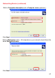
Networking Basics (continued) Enter a Computer description and a Computer name (optional.) Click Next Enter a Workgroup name. All computers on your network should have the same Workgroup name.
Networking Basics (continued) Please wait while the Network Setup Wizard applies the changes. When the changes are complete, Click Next. Please wait while the Network Setup Wizard configures the computer. This may take a few minutes.
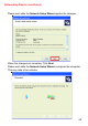
Networking Basics (continued) In the window below, select the option that fits your needs. In this example, Create a Network Setup Disk has been selected. You will run this disk on each of the computers on your network. Click Next. Insert a disk into the Floppy Disk Drive, in this case drive A.
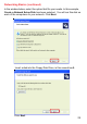
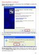
Networking Basics (continued) Please read the information under Here’s how in the screen below. After you complete the Network Setup Wizard you will use the Network Setup Disk to run the Network Setup Wizard once on each of the computers on your network. Click Next.
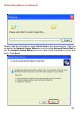
Networking Basics (continued) Please read the information on this screen, then click Finish to complete the Network Setup Wizard. The new settings will take effect when you restart the computer. Click Yes to restart the computer. You have completed configuring this computer. Next, you will need to run the Network Setup Disk on all the other computers on your network. After running the Network Setup Disk on all your computers, your new wireless network will be ready to use.
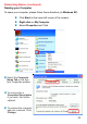
Networking Basics (continued) Naming your Computer To name your computer, please follow these directions:(In Windows XP) ! Click Start (in the lower left corner of the screen) ! Right-click on My Computer ! Select Properties and Click ! Select the Computer Name Tab in the System Properties window. ! You may enter a Computer Description if you wish; this field is optional. ! To rename the computer and join a domain, Click Change.
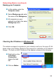
Networking Basics (continued) Naming your Computer ! In this window, enter the Computer name ! Select Workgroup and enter the name of the Workgroup ! All computers on your network must have the same Workgroup name. ! Click OK Checking the IP Address in Windows XP The adapter-equipped computers in your network must be in the same IP Address range (see Getting Started in this manual for a definition of IP Address Range.
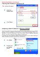
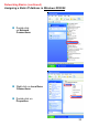
Networking Basics (continued) Checking the IP Address in Windows XP This window will appear. ! Click the Support tab ! Click Close Assigning a Static IP Address in Windows XP/2000 Note: Residential Gateways/Broadband Routers will automatically assign IP Addresses to the computers on the network, using DHCP (Dynamic Host Configuration Protocol) technology. If you are using a DHCP-capable Gateway/ Router you will not need to assign Static IP Addresses.
Networking Basics (continued) Assigning a Static IP Address in Windows XP/2000 ! Double-click on Network Connections ! Right-click on Local Area Connections ! Double-click on Properties 35
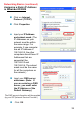
Networking Basics (continued) Assigning a Static IP Address in Windows XP/2000 ! Click on Internet Protocol (TCP/IP) ! Click Properties ! Input your IP Address and subnet mask. (The IP Addresses on your network must be within the same range. For example, if one computer has an IP Address of 192.168.0.2, the other computers should have IP Addresses that are sequential, like 192.168.0.3 and 192.168.0.4. The subnet mask must be the same for all the computers on the network.
Networking Basics (continued) Assigning a Static IP Address with Macintosh OSX ! Go to the Apple Menu and select System Preferences ! cClick on Network ! Select Built-in Ethernet in the Show pull-down menu ! Select Manually in the Configure pull-down menu ! Input the Static IP Address, the Subnet Mask and the Router IP Address in the appropriate fields ! Click Apply Now 37
Networking Basics (continued) Selecting a Dynamic IP Address with Macintosh OSX ! Go to the Apple Menu and select System Preferences ! Click on Network ! Select Built-in Ethernet in the Show pull-down menu ! Select Using DHCP in the Configure pull-down menu ! Click Apply Now ! The IP Address, Subnet mask, and the Router’s IP Address will appear in a few seconds 38
Networking Basics (continued) Checking the Wireless Connection by Pinging in Windows XP and 2000 ! Go to Start > Run > type cmd. A window similar to this one will appear. Type ping xxx.xxx.xxx.xxx, where xxx is the IP Address of the Wireless Router or Access Point. A good wireless connection will show four replies from the Wireless Router or Acess Point, as shown. Checking the Wireless Connection by Pinging in Windows Me and 98 ! Go to Start > Run > type command. A window similar to this will appear.
Troubleshooting This Chapter provides solutions to problems that can occur during the installation and operation of the DWL-2000AP Wireless Access Point. We cover various aspects of the network setup, including the network adapters. Please read the following if you are having problems. Note: It is recommended that you use an Ethernet connection to configure the DWL-2000AP Wireless Access Point. 1.The computer used to configure the DWL-2000AP cannot access the Configuration menu.
Troubleshooting (continued) 2. The wireless client cannot access the Internet in the Infrastructure mode. Make sure the wireless client is associated and joined with the correct Access Point. To check this connection: Right-click on the Local Area Connection icon in the taskbar> select View Available Wireless Networks. The Connect to Wireless Network screen will appear. Please make sure you have selected the correct available network, as shown in the illustration below.
Troubleshooting (continued) 2. The wireless client cannot access the Internet in the Infrastructure mode. (continued) ! Check to make sure that the Router in your network is functioning properly by pinging it. If the router is not functioning properly, it will not connect to the Internet. If you need to find out how to ping network devices, please refer to “Checking the Wireless Connection by pinging” in the Networking Basics section of this manual.
Troubleshooting (continued) ! Double-click on Network Adapters ! Right-click on D-Link AirPlus DWL-G650 Wireless Cardbus Adapter (In this example we use the DWL-G650; you may be using other network adapters, but the procedure will remain the same.
Troubleshooting (continued) 4. What variables may cause my wireless products to lose reception? D-Link products let you access your network from virtually anywhere you want. However, the positioning of the products within your environment will affect the wireless range. Please refer to Installation Considerations in the Wireless Basics section of this manual for further information about the most advantageous placement of your D-Link wireless products. 5.
Troubleshooting (continued) 6. Why can’t I get a wireless connection? (continued) ! Turn off your DWL-2000AP and the client. Turn the DWL-2000AP back on again, and then turn on the client. ! Make sure that all devices are set to Infrastructure mode. ! Check that the LED indicators are indicating normal activity. If not, check that the AC power and Ethernet cables are firmly connected. ! Check that the IP Address, subnet mask, and gateway settings are correctly entered for the network.
Troubleshooting (continued) 8. Resetting the DWL-2000AP to Factory Default Settings After you have tried other methods for troubleshooting your network, you may choose to Reset the DWL-2000AP to the factory default settings.
Technical Specifications Standards ! IEEE 802.11g-Draft ! IEEE 802.11 ! IEEE 802.11b ! IEEE 802.3 ! IEEE 802.
Technical Specifications (continued) Receiver Sensitivity: ! 54Mbps OFDM, 10% PER, -68dBm ! 48Mbps OFDM, 10% PER, -68dBm ! 36Mbps OFDM, 10% PER, -75dBm ! 24Mbps OFDM, 10% PER, -79dBm ! 18Mbps OFDM, 10% PER, -82dBm ! 12Mbps OFDM, 10% PER, -84dBm ! 11Mbps CCK, 8% PER, -82dBm ! 9Mbps OFDM, 10% PER, -87dBm ! 6Mbps OFDM, 10% PER, -88dBm ! 5.5Mbps CCK, 8% PER, -85dBm ! 2Mbps QPSK, 8% PER, -86dBm ! 1Mbps BPSK, 8% PER, -89dBm Physical Dimensions: ! L = 5.6 inches (142mm) ! W = 4.3 inches (109mm) ! H = 1.
Technical Specifications (continued) Media Access Control: ! CSMA/CA with ACK Power Input: ! Ext. Power Supply DC 5V, 2.0A Weight: ! .44 lbs.
Technical Support You can find software updates and user documentation on the D-Link website. D-Link provides free technical support for customers within the United States and within Canada for the duration of the warranty period on this product. U.S. and Canadian customers can contact D-Link technical support through our web site, or by phone. Tech Support for customers within the United States: D-Link Technical Support over the Telephone: (877) 453-5465 24 hours a day, seven days a week.
Warranty and Registration Subject to the terms and conditions set forth herein, D-Link Systems, Inc. (“D-Link”) provides this Limited warranty for its product only to the person or entity that originally purchased the product from: D-Link or its authorized reseller or distributor and Products purchased and delivered within the fifty states of the United States, the District of Columbia, U.S. Possessions or Protectorates, U.S. Military Installations, addresses with an APO or FPO.
The original product owner must obtain a Return Material Authorization (“RMA”) number from the Authorized D-Link Service Office and, if requested, provide written proof of purchase of the product (such as a copy of the dated purchase invoice for the product) before the warranty service is provided.
Governing Law: This Limited Warranty shall be governed by the laws of the State of California. Some states do not allow exclusion or limitation of incidental or consequential damages, or limitations on how long an implied warranty lasts, so the foregoing limitations and exclusions may not apply. This limited warranty provides specific legal rights and the product owner may also have other rights which vary from state to state. Trademarks: D-Link is a registered trademark of D-Link Systems, Inc.