Table of Contents Introducing the D-Link Mobility System..........................................................................................1 D-Link Mobility System..................................................................................................................1 Using the Command-Line Interface.................................................................................................2 Text and Syntax: Conventions...................................................................
IGMP Snooping Commands.........................................................................................................450 Security ACL Commands.............................................................................................................469 Trace Commands...........................................................................................................................490 Snoop Commands............................................................................................
Introducing the D-Link Mobility System Read this reference if you are a network administrator responsible for managing DWS-1008 switches and DWL-8220AP access points in a network. D-Link Mobility System The D-Link Mobility System is an enterprise-class WLAN solution that seamlessly integrates with an existing wired enterprise network.
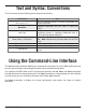
Text and Syntax: Conventions This CLI manual uses the following text and syntax conventions: Convention Monospace Text Bold Text Italic Text Menu Name > Command [ ] (square brackets) { } (curly brackets) | (vertical bar) Use Sets off command syntax or sample commands and system responses. Highlights commands that you enter or items you select. Designates command variables that you replace with appropriate values, or highlights publication titles or words requiring special emphasis.
CLI Conventions Be aware of the following MSS CLI conventions for command entry: • “Command Prompts” on page 3 • “Syntax: Notation” on page 4 • “Text Entry Conventions and Allowed Characters” on page 4 • “User Globs, MAC Address Globs, and VLAN Globs” on page 6 • “Port Lists” on page 8 Command Prompts By default, the MSS CLI provides the following prompt for restricted users.
Syntax: Notations The MSS CLI uses standard syntax notation: • Bold monospace font identifies the command and keywords you must type. For example: set enable pass • Italic monospace font indicates a placeholder for a value. For example, you replace vlan-id in the following command with a virtual LAN (VLAN) ID: clear interface vlan-id ip • Curly brackets ({ }) indicate a mandatory parameter, and square brackets ([ ]) indicate an optional parameter.
MAC Address Notation MSS displays MAC addresses in hexadecimal numbers with a colon (:) delimiter between bytes—for example, 00:01:02:1a:00:01. You can enter MAC addresses with either hyphen (-) or colon (:) delimiters, but colons are preferred. For shortcuts: • You can exclude leading zeros when typing a MAC address. MSS displays of MAC addresses include all leading zeros.
Globs Name “globbing” is a way of using a wildcard pattern to expand a single element into a list of elements that match the pattern. MSS accepts user globs, MAC address globs, and VLAN globs. The order in which globs appear in the configuration is important, because once a glob is matched, processing stops on the list of globs User Globs A user glob is shorthand method for matching an authentication, authorization, and accounting (AAA) command to either a single user or a set of users.
MAC Address Globs A media access control (MAC) address glob is a similar method for matching some authentication, authorization, and accounting (AAA) and forwarding database (FDB) commands to one or more 6-byte MAC addresses.
Port Lists The physical Ethernet ports on a switch can be set for connection to access points, authenticated wired users, or the network backbone. You can include a single port or multiple ports in one MSS CLI command by using the appropriate list format. The ports on a switch are numbered 1 through 8. No port 0 exists on the switch. You can include a single port or multiple ports in a command that includes port port-list. Use one of the following formats for port-list: • A single port number.
Command-Line Editing MSS editing functions are similar to those of many other network operating systems. Keyboard Shortcuts The following keyboard shortcuts are available for entering and editing CLI commands: Keyboard Shortcut(s) Ctrl+A Ctrl+B or Left Arrow key Ctrl+C Ctrl+D Ctrl+E Ctrl+F or Right Arrow key Ctrl+K Ctrl+L or Ctrl+R Ctrl+N or Down Arrow key Ctrl+P or Up Arrow key Ctrl+U or Ctrl+X Ctrl+W Esc B Esc D Delete key or Backspace key Function Jumps to the first character of the command line.
Single-Asterisk (*) Wildcard Character You can use the single-asterisk (*) wildcard character in globbing. For details, see “User Globs, MAC Address Globs, and VLAN Globs” on page 7. Double-Asterisk (**) Wildcard Characters The double-asterisk (**) wildcard character matches all usernames. For details, see “User Globs” on page 6. Using CLI Help The CLI provides online help.
Understanding Command Descriptions Each command description in the D-Link Command Reference contains the following elements: • A command name, which shows the keywords but not the variables. For example, the following command name appears at the top of a command description and in the index: set {ap | dap} name The set {ap | dap} name command has the following complete syntax: set {ap port-list | dap dap-num} name name • A brief description of the command’s functions. • The full command syntax.
Access Commands Use access commands to control access to the Mobility Software System (MSS) (CLI). This chapter presents access commands alphabetically. Use the following table to locate commands in this chapter based on their use. disable Defaults: None. Access: Enabled. enable Places the CLI session in enabled mode, which provides access to all commands required for configuring and monitoring the system. Syntax: enable Access: All.
quit Exit from the CLI session. Syntax: quit Defaults: None. Access: All. Examples: To end the administrator’s session, type the following command: DWS-1008> quit set enablepass Sets the password that provides enabled access (for configuration and monitoring) to the switch. Syntax: set enablepass Defaults: None. Access: Enabled. Usage: After typing the set enablepass command, press Enter. If you are entering the first enable password on this switch, press Enter at the Enter old password prompt.
System Services Commands Use system services commands to configure and monitor system information for a DWS-1008 switch. This chapter presents system services commands alphabetically. Use the following table to located commands in this chapter based on their use.
clear banner motd Syntax: clear banner motd Defaults: None. Access: Enabled. Examples: To clear a banner, type the following command: DWS-1008> clear banner motd success: change accepted Note: As an alternative to clearing the banner, you can overwrite the existing banner with an empty banner by typing the following command: set banner motd ^^ clear history Deletes the command history buffer for the current CLI session. Syntax: clear history Defaults: None. Access: All.
clear system Clears the system configuration of the specified information. Syntax: clear system [contact | countrycode | idle-timeout | ip-address | location | name] contact Resets the name of contact person for the DWS-1008 switch to null. countrycode Resets the country code for the DWS-1008 switch to null. idle-timeout Resets the number of seconds a CLI management session can remain idle to the default value (3600 seconds). ip-address Resets the IP address of the DWS-1008 switch to null.
help Syntax: clear history Defaults: None. Access: All. Examples: Use this command to see a list of available commands. If you have restricted access, you see fewer commands than if you have enabled access.
history Syntax: clear history Defaults: None. Access: All. Examples: To show the history of your session, type the following command: DWS-1008# history quickstart Runs a script that interactively helps you configure a new switch. Caution! The quickstart command is for configuration of a new switch only. After prompting you for verification, the command erases the switch’s configuration before continuing.
set banner motd Configures the banner string that is displayed before the beginning of each login prompt for each CLI session on the DWS-1008 switch. Syntax: set banner motd ^text^ Defaults: None. Access: Enabled. Usage: Type a caret (^), then the message, then another caret.
set confirm Enables or disables the display of confirmation messages for commands that might have a large impact on the network. Syntax: set confirm {on | off} on Enables confirmation messages. off Disables confirmation messages. Defaults: Configuration messages are enabled. Access: Enabled. Usage: This command remains in effect for the duration of the session, until you enter an exit or quit command, or until you enter another set confirm command.
Usage: Use this command if the output of a CLI command is greater than the number of lines allowed by default for a terminal type. Examples: To set the number of lines displayed to 100, type the following command: DWS-1008# set length 100 success: screen length for this session set to 100 set license Installs an upgrade license key on a DWS-1008 switch. The DWS-1008 can boot and manage up to 32 APs by default.
set prompt Changes the CLI prompt for the DWS-1008 switch to a string you specify. Syntax: set prompt string string Alphanumeric string up to 32 characters long. To include spaces in the prompt, you must enclose the string in double quotation marks (“”). Defaults: The factory default for the DWS switch prompt is DWS-mm-nnnnnn, where mm is the model number and nnnnnn is the last 6 digits of the 12-digit system MAC address. Access: Enabled.
set system contact Stores a contact name for the DWS-1008 switch. Syntax: set system contact string string Alphanumeric string up to 256 characters long, with no blank spaces. Defaults: None. Access: Enabled. To view the system contact string, type the show system command. Examples: The following command sets the system contact information to tamara@example.com: DWS-1008# set system contact tamara@example.com success: change accepted.
D-Link DWS-1008 CLI Manual 24
Defaults: None. Access: Enabled. Usage: You must set the system county code to a valid value before using any set ap commands to configure an access point. Examples: To set the country code to Canada, type the following command: DWS-1008# set system country code CA success: change accepted. See Also: • show config set system idle-timeout Specifies the maximum number of seconds a CLI management session with the switch can remain idle before MSS terminates the session.
Access: Enabled. Usage: This command applies to all types of CLI management sessions: console, Telnet, and SSH. The timeout change applies to existing sessions only, not to new sessions. Examples: The following command sets the idle timeout to 1800 seconds (one half hour): DWS-1008# set system idle-timeout 1800 success: change accepted. See Also: • clear system • show system set system ip-address Sets the system IP address so that it can be used by various services in the DWS-1008 switch.
set system location Stores location information for the DWS-1008 switch. Syntax: set system location string string Alphanumeric string up to 256 characters long, with no blank spaces. Defaults: None. Access: Enabled. To view the system location string, type the show system command. Examples: To store the location of the switch in the switch’s configuration, type the following command: DWS-1008# set system location first-floor-bldg3 success: change accepted.
Usage: Entering set system name with no string resets the system name to the factory default. To view the system name string, type the show system command. Examples: The following example sets the system name to a name that identifies the DWS switch: DWS-1008# set system name DWS-bldg3 success: change accepted.
show licenses Displays information about the license key(s) currently installed on an DWS-1008 switch. Syntax: show licenses Defaults: None. Access: All Examples: To view license keys, type the following command: DWS-1008# show licenses Feature : 80 additional APs See Also: • set license show load Displays CPU usage on a DWS-1008 switch. Syntax: show load Defaults: None. Access: Enabled.
show system Displays system information. Syntax: show system Defaults: None. Access: Enabled. Examples: To show system information, type the following command: DWS-1008# show system The table on the next page describes the fields of show system output.
Field Product Name Description DWS model number. System name (factory default, or optionally configured with set system name). System Countrycode Country-specific 802.11 code required for AP operation. (configured with set system countrycode) Total Power Over Total power that the DWS-1008 is currently supplying to its directly connected Ethernet access points, in watts. System Location Record of the DWS switch’s physical location (optionally configured with set system location).
Field Memory Total Power Over Ethernet Description Current size (in megabytes) of nonvolatile memory (NVRAM) and synchronous dynamic RAM (SDRAM), plus the percentage of total memory space in use, in the following format: NVRAM size /SDRAM size (percent of total) Total power that the DWS-1008 is currently supplying to its directly connected access points, in watts.
Port Commands Use port commands to configure and manage individual ports and load-sharing port groups. This chapter presents port commands alphabetically. Use the following table to locate commands in this chapter based on their use.
clear dap Caution: When you clear a Distributed AP, MSS ends user sessions that are using the AP. Removes a Distributed AP. Syntax: clear dap dap-num dap-num Number of the Distributed AP(s) you want to remove. Defaults: None. Access: Enabled. Examples: The following command clears Distributed AP 1: DWS-1008# clear dap 1 This will clear specified DAP devices.
clear port-group Removes a port group Syntax: clear port-group name name name Name of the port group. Defaults: None. Access: Enabled. Examples: The following command clears port group server1: DWS-1008# clear port-group name server1 success: change accepted. See Also: • set port-group clear port mirror Removes a port mirroring configuration. Syntax: clear port mirror Defaults: None. Access: Enabled.
clear port name Removes the name assigned to a port. Syntax: clear port port-list name List of physical ports. MSS removes the names from all the specified ports. port-list Defaults: None. Access: Enabled. Examples: The following command clears the names of ports 1 through 4: DWS-1008# clear port 1-4 name See Also: • set port name clear port type Caution: When you clear a port, MSS ends user sessions that are using the port.
Port Parameter Setting VLAN membership None. Note: Although the command changes a port to a network port, the command does not place the port in any VLAN. To use the port in a VLAN, you must add the port to the VLAN. Spanning Tree Protocol Based on the VLAN(s) you add the port to. (STP) 802.1X No authorization. Port groups None. Internet Group Enabled as port is added to VLANs. Management Protocol (IGMP) snooping Access: point and radio Not applicable. parameters Maximum user sessions Not applicable.
monitor port counters Displays and continually updates port statistics. Syntax: monitor port counters [octets | packets | receive-errors | transmit-errors | collisions | receive-etherstats | transmit-etherstats] octets Displays octet statistics first. packets Displays packet statistics first. recieve-errors Displays errors in received packets first. transmit-errors Displays errors in transmitted packets first. collisions Displays collision statistics first.
Usage: Each type of statistic is displayed separately. Press the Spacebar to cycle through the displays for each type. If you use an option to specify a statistic type, the display begins with that statistic type. You can use one statistic option with the command. Use the keys listed the following table to control the monitor display Key Effect on monitor display Spacebar Advances to the next statistic type. Esc Exits the monitor. MSS stops displaying the statistics and displays a new command prompt.
Table: Output for monitor port counters Statistics Option Displayed for All Options Field Description Port Port the statistics are displayed for. Status Port status. The status can be Up or Down. Total numbewr of octets reveived by the port. Rx Octets This number includes octets received in frames that contained errors. octets Total number of octets transmitted. Tx Octets Rx Unicast This number includes octets transmitted in frames that contained errors. Number of unicast packets received.
Statistics Option Transmit-errors Field Tx Crc Number of frames transmitted by the port that had the correct length but contained an invalid FCS value. Tx Short Number of frames transmitted by the port that were fewer than 64 bytes long. Tx Fragment Total number of frames transmitted that were less than 64 octets long and had invalid CRCs. Tx Abort Total number of frames that had a link pointer parity error.
reset port Resets a port by toggling its link state and Power over Ethernet (PoE) state. Syntax: reset port port-list port-list List of physical ports. MSS resets all the specified ports. Defaults: None. Access: Enabled. Usage: The reset command disables the port’s link and PoE (if applicable) for at least 1 second, then reenables them. This behavior is useful for forcing an AP access point that is connected to two DWS-1008 switches to reboot over the link to the other switch.
Access: Enabled. Examples: The following command configures Distributed AP 1 for AP model MP-372 with serial-ID 0322199999: DWS-1008# set dap 1 serial-id 0322199999 model mp-372 success: change accepted. The following command removes Distributed AP 1: DWS-1008# clear dap 1 This will clear specified DAP devices. Would you like to continue? (y/n) [n]y See Also: • clear dap • clear port type • set port type ap • set system countrycode set port Administratively disables or reenables a port.
The following command reenables the port: DWS-1008# set port enable 4 success: set “enable” on port 4 See Also: • set reset port set port-group Administratively disables or reenables a port. Syntax: set port-group name group-name port-list mode {on | off} name group-name port-list mode {on | off} Alphanumeric string of up to 255 characters, with no spaces. List of physical ports. All the ports you specify are configured together as a single logical link. State of the group.
The following commands disable the link for port group server1, change the list of ports in the group, and reenable the link: DWS-1008# set port-group name server1 1-5 mode off success: change accepted. DWS-1008# set port-group name server1 1-4,7 mode on success: change accepted.
set port mirror Configures port mirroring. Port mirroring is a troubleshooting feature that copies (mirrors) traffic sent or received by a DWS-1008 port (the source port) to another port (the observer) on the same DWS-1008. You can attach a protocol analyzer to the observer port to examine the source port’s traffic. Both traffic directions (send and receive) are mirrored. Syntax: set port mirror source-port observer observer-port Number of the port whose traffic you want to analyze.
Defaults: None Access: Enabled. Usage: To simplify configuration and avoid confusion between a port’s number and its name, D-Link recommends that you do not use numbers as port names. Examples: The following command sets the name of port 4 to adminpool: DWS-1008# set port 4 name adminpool success: change accepted. See Also: • clear port name set port negotiation Disables or reenables autonegotiation on gigabit Ethernet or 10/100 Ethernet ports.
A stream of large packets sent to an DWS-1008 port in such a configuration can cause forwarding on the link to stop. Examples: The following command disables autonegotiation on ports 1, 2, and 4 through 6: DWS-1008# set port negotiation 1,2,4-6 disable The following command enables autonegotiation on port 5: DWS-1008# set port negotiation 5 enable set port poe Enables or disables Power over Ethernet (PoE) on ports connected to AP access points.
DWS-1008# set port poe 3,5 disable If you are enabling power on these ports, they must be connected only to approved PoE devices with the correct wiring. Do you wish to continue? (y/n) [n]y The following command enables PoE on ports 2 and 4: DWS-1008# set port poe 2,4 enable If you are enabling power on these ports, they must be connected only to approved PoE devices with the correct wiring.
Examples: The following command sets the port speed on ports 1, 3 through 5, and 8 to 10 Mbps and sets the operating mode to full-duplex: DWS-1008# set port speed 1,3-5,8 10 set port trap Enables or disables Simple Network Management Protocol (SNMP) linkup and linkdown traps on an individual port. Syntax: set port trap port-list {enable | disable} port-list enable disable List of physical ports. Enables the Telnet server. Disables the Telnet server.
set port type ap Configures a DWS-1008 switch port for an (AP) access point. Caution! When you set the port type for AP use, you must specify the PoE state (enable or disable) of the port. Use the DWS-1008’s PoE to power D-Link access points or PoE enabled devices only. If you enable PoE on a port connected to another device, physical damage to the device can result. Note: Before configuring a port as an AP port, you must use the set system countrycode command to set the IEEE 802.
Port Parameter Setting VLAN Membership Removed from all VLANs. You cannot assign an AP access port to a VLAN. MSS automatically assigns AP access ports to VLANs based on user traffic. Spanning Tree Protocol (STP) 802.1x Port Groups IGMP Snooping Maximum user sessions Not applicable. Uses authentication parameters configured for users. Not applicable. Enabled as users are authenticated and join VLANs.
set port type wired-auth Configures an DWS-1008 port for a wired authentication user. Syntax: set port type wired-auth port-list [tag tag-list] [max-sessions num] [auth-fall-thru {last-resort | none | web-portal}] port-list tag-list num last-resort none web-portal List of physical ports. One or more numbers between 1 and 4094 that subdivide a wired authentication port into virtual ports. Maximum number of simultaneous user sessions supported.
For 802.1X clients, wired authentication works only if the clients are directly attached to the wired authentication port, or are attached through a hub that does not block forwarding of packets from the client to the PAE group address (01:80:c2:00:00:03). Wired authentication works in accordance with the 802.1X specification, which prohibits a client from sending traffic directly to an authenticator’s MAC address until the client is authenticated.
show port counters Displays port statistics. Syntax: show port counters [octets | packets | receive-errors | transmit-errors | collisions | receive-etherstats | transmit-etherstats] [port port-list] octets packets receive-errors transmit-errors collisions receive-etherstats transmit-etherstats port port-list Displays octet statistics. Displays packet statistics. Displays errors in received packets. Displays errors in transmitted packets.
show port-group Displays port group information. Syntax: show port-group [name group-name] name group-name Displays information for the specified port group. Defaults: None. Access: All. Examples: The following command displays the configuration of port group server2: DWS-1008# show port-group name server2 Port group: server2 is up Ports: 3, 5 The table below describes the fields in the show port-group output. Field Description Port group Name and state (enabled or disabled) of the port group.
show port poe Displays status information for ports on which Power over Ethernet (PoE) is enabled. Syntax: show port poe [port-list] port-list List of physical ports. If you do not specify a port list, PoE information is displayed for all ports. Defaults: None. Access: All.
show port status Displays configuration and status information for ports. Syntax: show port status [port-list] port-list List of physical ports. If you do not specify a port list, information is displayed for all ports. Defaults: None. Access: All.
VLAN Commands Use virtual LAN (VLAN) commands to configure and manage parameters for individual port VLANs on network ports, and to display information about clients within a network. This chapter presents VLAN commands alphabetically. Use the following table to locate commands in this chapter based on their use.
clear fdb Deletes an entry from the forwarding database (FDB). Syntax: clear fdb {perm | static | dynamic | port port-list} [vlan vlan-id] [tag tag-value] perm Clears permanent entries. A permanent entry does not age out and remains in the database even after a reboot, reset, or power cycle. You must specify a VLAN name or number with this option. static Clears static entries. A static entry does not age out, but is removed from the database after a reboot, reset, or power cycle.
clear security l2-restrict Removes one or more MAC addresses from the list of destination MAC addresses to which clients in a VLAN are allowed to send traffic at Layer 2. Syntax: clear security l2-restrict vlan vlan-id [permit-mac mac-addr [mac-addr] | all] vlan-id VLAN name or number. permit-mac mac-addr [mac-addr] List of MAC addresses. MSS no longer allows clients in the VLAN to send traffic to the MAC addresses at Layer 2. all Removes all MAC addresses from the list.
clear security l2-restrict counters Clear statistics counters for Layer 2 forwarding restriction. Syntax: clear security l2-restrict counters [vlan vlan-id | all] vlan-id VLAN name or number. all Clears Layer 2 forwarding restriction counters for all VLANs. Defaults: If you do not specify a VLAN or all, counters for all VLANs are cleared. Access: Enabled.
Defaults: None. Access: Enabled. Usage: If you do not specify a port-list, the entire VLAN is removed from the configuration. Note: You cannot delete the default VLAN but you can remove ports from it. To remove ports from the default VLAN, use the port port-list option. Examples: The following command removes port 1 from VLAN green: DWS-1008# clear vlan green port 1 This may disrupt user connectivity. Do you wish to continue? (y/n) [n]y success: change accepted.
set fdb Adds a permanent or static entry to the forwarding database. Syntax: set fdb {perm | static} mac-addr port port-list vlan vlan-id [tag tag-value] perm Adds a permanent entry. A permanent entry does not age out and remains in the database even after a reboot, reset, or power cycle. static Adds a static entry. A static entry does not age out, but is removed from the database after a reboot, reset, or power cycle. mac-addr Destination MAC address of the entry.
set fdb agingtime Changes the aging timeout period for dynamic entries in the forwarding database. Syntax: set fdb agingtime vlan-id age seconds vlan-id VLAN name or number. The timeout period change applies only to entries that match the specified VLAN. age seconds Value for the timeout period, in seconds. You can specify a value from 0 through 1,000,000. If you change the timeout period to 0, aging is disabled. Defaults: The aging timeout period is 300 seconds (5 minutes). Access: Enabled.
Defaults: Layer 2 restriction is disabled by default. Access: Enabled. Usage: You can specify multiple addresses by listing them on the same command line or by entering multiple commands. To change a MAC address, use the clear security l2-restrict command to remove it, then use the set security l2-restrict command to add the correct address. Restriction of client traffic does not begin until you enable the permitted MAC list. Use the mode enable option with this command.
VLAN names are case-sensitive for RADIUS authorization when a client roams to a switch. If the switch is not configured with the VLAN the client is on, but is configured with a VLAN that has the same spelling but different capitalization, authorization for the client fails. For example, if the client is on VLAN red but the switch to which the client roams has VLAN RED instead, RADIUS authorization fails.
show fdb Displays entries in the forwarding database. Syntax: show fdb [mac-addr-glob [vlan vlan-id]] show fdb {perm | static | dynamic | system | all} [port port-list | vlan vlan-id] mac-addr-glob A single MAC address or set of MAC addresses. Specify a MAC address, or use the wildcard character (*) to specify a set of MAC addresses. vlan vlan-id Name or number of a VLAN for which to display entries. perm Displays permanent entries.
The top line of the display identifies the characters to distinguish among the entry types. The following command displays all entries that begin with the MAC address glob 00: DWS-1008# show fdb 00:* * = Static Entry. + = Permanent Entry. # = System Entry.
show fdb count Lists the number of entries in the forwarding database. Syntax: show fdb count {perm | static | dynamic} [vlan vlan-id] perm Lists the number of permanent entries. A permanent entry does not age out and remains in the database even after a reboot, reset, or power cycle. static Lists the number of static entries. A static entry does not age out, but is removed from the database after a reboot, reset, or power cycle. dynamic Lists the number of dynamic entries.
Examples: The following command shows Layer 2 forwarding restriction information for all VLANs: DWS-1008# show security l2-restrict VLAN Name En Drops Permit MAC Hits ------------------------------------------------------------------------------------------------1 default Y 0 00:0b:0e:02:53:3e 5947 00:30:b6:3e:5c:a8 9 2 vlan-2 Y 0 04:04:04:04:04:04 0 The table describes the fields in the display. Field Discription VLAN VLAN number. Name VLAN name.
Examples: The following command displays information for VLAN burgundy: DWS-1008# show vlan config burgundy Admin VLAN Tunl Port VLAN Name Status State Affin Port Tag State ------------------------------------------------------------------------------------------------------2 burgundy Up Up 5 2 none Up 3 none Up 4 none Up 5 none Up 6 none Up t:10.10.40.
Quality of Service Commands Use Quality of Service (QoS) commands to configure packet prioritization in MSS. Packet prioritization ensures that DWS-1008 switches and DWL-8220AP access points give preferential treatment to highpriority traffic such as voice and video. This chapter presents QoS commands alphabetically. Use the following table to locate commands in this chapter based on their use.
Defaults: None. Access: Enabled. Usage: To reset all mappings to their default values, use the clear qos command without the optional parameters. Examples: The following command resets all QoS mappings: DWS-1008# clear qos success: change accepted. The following command resets the mapping used to classify packets with DSCP value 44: DWS-1008# clear qos dscp-to-qos-map 44 success: change accepted.
set qos dscp-to-cos-map Changes the internal QoS value to which MSS maps a packet’s DSCP value when classifying inbound packets. Syntax: set qos dscp-to-cos-map dscp-range cos level dscp-range DSCP range. You can specify the values as decimal numbers. Valid decimal values are 0 to 63. To specify a range, use the following format: 40-56. Specify the lower number first. cos level Internal QoS value. You can specify a number from 0 to 7.
Examples: The following command displays the default QoS settings: DWS-1008# show qos default Ingress QoS Classification Map (dscp-to-cos) Ingress DSCP CoS Level =============================================================== 00-09 0 0 0 0 0 0 0 0 1 1 10-19 1 1 1 1 1 1 2 2 2 2 20-29 2 2 2 2 3 3 3 3 3 3 30-39 3 3 4 4 4 4 4 4 4 4 40-49 5 5 5 5 5 5 5 5 6 6 50-59 6 6 6 6 6 6 7 7 7 7 60-63 7 7 7 7 Egress QoS Mark
IP Services Commands Use IP services commands to configure and manage IP interfaces, management services, the Domain Name Service (DNS), Network Time Protocol (NTP), and aliases, and to ping a host or trace a route. This chapter presents IP services commands alphabetically. clear interface Removes an IP interface. Syntax: clear interface vlan-id ip vlan-id VLAN name or number. Defaults: None. Access: Enabled.
clear ip alias Removes an alias, which is a string that represents an IP address. Syntax: clear ip alias name name Alias name. Defaults: None. Access: Enabled. Examples: The following command removes the alias server1: DWS-1008# clear ip alias server1 success: change accepted. See Also: • set ip alias • show ip alias clear ip dns domain Removes the default DNS domain name. Syntax: clear ip dns domain Defaults: None. Access: Enabled.
clear ip dns server Removes a DNS server from a DWS-1008 switch configuration. Syntax: clear ip dns server ip-addr ip-addr IP address of a DNS server. Defaults: None. Access: Enabled. Examples: The following command removes DNS server 10.10.10.69 from a switch’s configuration: DWS-1008# clear ip dns server 10.10.10.69 success: change accepted.
Defaults: None. Access: Enabled. Examples: The following command removes the route to destination 10.10.10.68/24 through router 10.10.10.1: DWS-1008# clear ip route 10.10.10.68/24 10.10.10.1 success: change accepted. See Also: • set ip route • show ip route clear ip telnet Resets the Telnet server’s TCP port number to its default value. A DWS-1008 switch listens for Telnet management traffic on the Telnet server port. Syntax: clear ip telnet Defaults: The default Telnet port number is 23.
clear ntp server Removes an NTP server from a switch configuration. Syntax: clear ntp server {ip-addr | all} ip-addr IP address of the server to remove, in dotted decimal notation. all Removes all NTP servers from the configuration. Defaults: None. Access: Enabled. Examples: The following command removes NTP server 192.168.40.240 from a switch configuration: DWS-1008# clear ntp server 192.168.40.240 success: change accepted.
clear snmp community Clears an SNMP community string. Syntax: clear snmp community name comm-string comm-string Name of the SNMP community you want to clear. Defaults: None. Access: Enabled. Examples: The following command clears community string setswitch2: DWS-1008# clear snmp community name setswitch2 success: change accepted. See Also: • set snmp community • show snmp community clear snmp notify profile Clears an SNMP notification profile.
clear snmp notify target Clears an SNMP notification target. Syntax: clear snmp notify target target-num target-num ID of the target. Defaults: None. Access: Enabled. Examples: The following command clears notification target 3: DWS-1008# clear snmp notify target 3 success: change accepted. See Also: • set snmp notify target • show snmp notify target clear snmp usm Clears an SNMPv3 user. Syntax: clear snmp usm usm-username usm-username Name of the SNMPv3 user you want to clear.
clear summertime Clears the summertime setting from a DWS-1008 switch. Syntax: clear summertime Defaults: None. Access: Enabled. Examples: To clear the summertime setting from a switch, type the following command: DWS-1008# clear summertime success: change accepted. See Also: • clear timezone • set summertime • set timedate • set timezone • show summertime • show timedate • show timezone clear system ip-address Clears the system IP address.
clear timezone Clears the time offset for the switch’s real-time clock from Coordinated Universal Time (UTC). UTC is also know as Greenwich Mean Time (GMT). Syntax: clear timezone Defaults: None. Access: Enabled. Examples: To return the switch’s real-time clock to UTC, type the following command: DWS-1008# clear timezone success: change accepted.
interval time size size Time interval between ping packets, in milliseconds. You can specify from 100 through 10,000. Packet size, in bytes. You can specify from 56 through 65,507. Note: Because the switch adds header information, the ICMP packet size is 8 bytes larger than the size you specify. source-ip ip-addr IP address, in dotted decimal notation, to use as the source IP address in the ping packets.
set arp Adds an ARP entry to the ARP table. Syntax: set arp {permanent | static | dynamic} ip-addr mac-addr permanent Adds a permanent entry. A permanent entry does not age out and remains in the database even after a reboot, reset, or power cycle. static Adds a static entry. A static entry does not age out, but the entry does not remain in the database after a reboot, reset, or power cycle. dynamic Adds a dynamic entry.
Access: Enabled. Usage: Aging applies only to dynamic entries. To reset the ARP aging timeout to its default value, use the set arp agingtime 1200 command.
Examples: The following command configures IP interface 10.10.10.10/24 on VLAN default: DWS-1008# set interface default ip 10.10.10.10/24 success: set ip address 10.10.10.10 netmask 255.255.255.0 on vlan default The following command configures IP interface 10.10.20.10 255.255.255.0 on VLAN mauve: DWS-1008# set interface mauve ip 10.10.20.10 255.255.255.0 success: set ip address 10.10.20.10 netmask 255.255.255.
set interface dhcp-server Configures the MSS DHCP server. Note: Use of the MSS DHCP server to allocate client addresses is intended for temporary, demonstration deployments and not for production networks. D-Link recommends that you do not use the MSS DHCP server to allocate client addresses in a production network.
• DNS servers—If these options are not set with the set interface dhcp-server command’s primary-dns and secondary-dns options, the MSS DHCP server uses the values set by the set ip dns server command. • Default router—If this option is not set with the set interface dhcp-server command’s default-router option, the MSS DHCP server can use the value set by the set ip route command. A default route configured by set ip route can be used if the route is in the DHCP client’s subnet.
set ip alias Configures an alias, which maps a name to an IP address. You can use aliases as shortcuts in CLI commands. Syntax: set ip alias name ip-addr name String of up to 32 alphanumeric characters, with no spaces. ip-addr IP address in dotted decimal notation. Defaults: None. Access: Enabled. Examples: The following command configures the alias HR1 for IP address 192.168.1.2: DWS-1008# set ip alias HR1 192.168.1.2 success: change accepted.
set ip dns domain Configures a default domain name for DNS queries. The switch appends the default domain name to domain names or hostnames you enter in commands. Syntax: set ip dns domain name name Domain name of between 1 and 64 alphanumeric characters with no spaces (for example, example.org). Defaults: None. Access: Enabled. Usage: To override the default domain name when entering a hostname in a CLI command, enter a period at the end of the hostname.
Defaults: None. Access: Enabled. Usage: You can configure a DWS-1008 switch to use one primary DNS server and up to five secondary DNS servers. Examples: The following commands configure a DWS-1008 switch to use a primary DNS server and two secondary DNS servers: DWS-1008# set ip dns server 10.10.10.50/24 primary success: change accepted. DWS-1008# set ip dns server 10.10.20.69/24 secondary success: change accepted. DWS-1008# set ip dns server 10.10.30.69/24 secondary success: change accepted.
set ip route Adds a static route to the IP route table. Syntax: set ip route {default | ip-addr mask | ip-addr/mask-length} default-router metric default Default route. A DWS-1008 switch uses the default route if an explicit route is not available for the destination. Note: default is an alias for IP address 0.0.0.0/0. ip-addr mask IP address and subnet mask for the route destination, in dotted decimal notation (for example, 10.10.10.10 255.255.255.0).
Examples: The following command adds a default route that uses default router 10.5.4.1 and gives the route a cost of 1: DWS-1008# set ip route default 10.5.4.1 1 success: change accepted. The following commands add two default routes, and configure MSS to always use the route through 10.2.4.69 when the switch interface to that default router is up: DWS-1008# set ip route default 10.2.4.69 1 success: change accepted. DWS-1008# set ip route default 10.2.4.17 2 success: change accepted.
Examples: The following command enables the SNMP server on a DWS-1008 switch: DWS-1008# set ip snmp server enable success: change accepted. See Also: • clear snmp trap receiver • set port trap • set snmp community • set snmp trap • set snmp trap receiver • show snmp configuration set ip ssh Changes the TCP port number on which a DWS-1008 switch listens for Secure Shell (SSH) management traffic. Caution: If you change the SSH port number from an SSH session, MSS immediately ends the session.
set ip ssh server Disables or reenables the SSH server on a switch. Caution: If you disable the SSH server, SSH access to the switch is also disabled. Syntax: set ip ssh server {enable | disable} enable Enables the SSH server. disable Disables the SSH server. Defaults: The SSH server is enabled by default. Access: Enabled. Usage: SSH requires an SSH authentication key. You can generate one or allow MSS to generate one.
Defaults: The default Telnet port number is 23. Access: Enabled. Examples: The following command changes the Telnet port number on a switch to 5000: DWS-1008# set ip telnet 5000 success: change accepted. See Also: • clear ip telnet • set ip https server • set ip telnet server • show ip https • show ip telnet set ip telnet server Enables the Telnet server on a DWS-1008 switch. Caution: If you disable the Telnet server, Telnet access to the switch is also disabled.
set ntp Enables or disables the NTP client on a DWS-1008 switch. Syntax: set ntp {enable | disable} enable Enables the NTP client. disable Disables the NTP client. Defaults: The NTP client is disabled by default. Access: Enabled. Usage: If NTP is configured on a system whose current time differs from the NTP server time by more than 10 minutes, convergence of the switch time can take many NTP update intervals.
Examples: The following command configures a switch to use NTP server 192.168.1.5: DWS-1008# set ntp server 192.168.1.5 See Also: • clear ntp server • clear ntp update-interval • set ntp • set ntp update-interval • show ntp set ntp update-interval Changes how often MSS sends queries to the NTP servers for updates. Syntax: set ntp update-interval seconds seconds Number of seconds between queries. You can specify from 16 through 1024 seconds.
set snmp community Configures a community string for SNMPv1 or SNMPv2c. Note: For SNMPv3, use the set snmp usm command to configure an SNMPv3 user. SNMPv3 does not use community strings. Syntax: set snmp community name comm-string access {read-only | read-notify | notify-only | read-write | notify-read-write} comm-string Name of the SNMP community. Specify between 1 and 32 alphanumeric characters, with no spaces.
Examples: The following command configures the read-write community good_community: DWS-1008# set snmp community read-write good_community success: change accepted. The following command configures community string switchmgr1 with access level notify-readwrite: DWS-1008# set snmp community name switchmgr1 notify-read-write success: change accepted.
notification-type Name of the notification type: • APBootTraps—Generated when an access point boots. • ApNonOperStatusTraps—Generated to indicate an AP radio is nonoperational. • ApOperRadioStatusTraps—Generated when the status of an AP radio changes. • APTimeoutTraps—Generated when an access point fails to respond to the switch. • AuthenTraps—Generated when the switch’s SNMP engine receives a bad community string.
• CounterMeasureStopTraps—Generated when MSS stops countermeasures against a rogue access point. • DAPConnectWarningTraps—Generated when a Distributed AP whose fingerprint has not been configured in MSS establishes a management session with the switch. • DeviceFailTraps—Generated when an event with an Alert severity occurs. • DeviceOkayTraps—Generated when a device returns to its normal state. • LinkDownTraps—Generated when the link is lost on a port.
all Sends or drops all notifications. Defaults: A default notification profile (named default) is already configured in MSS. All notifications in the default profile are dropped by default. Access: Enabled. Examples: The following command changes the action in the default notification profile from drop to send for all notification types: DWS-1008# set snmp notify profile default send all success: change accepted.
DWS-1008# set snmp notify profile snmpprof_rfdetect send RFDetectSpoofedSsidAPTraps success: change accepted. DWS-1008# set snmp notify profile snmpprof_rfdetect send RFDetectUnAuthorizedAPTraps success: change accepted. DWS-1008# set snmp notify profile snmpprof_rfdetect send RFDetectUnAuthorizedOuiTraps success: change accepted. DWS-1008# set snmp notify profile snmpprof_rfdetect send RFDetectUnAuthorizedSsidTraps success: change accepted.
snmp-engine-id {ip | hex hex-string} SNMP engine ID of the target. Specify ip if the target’s SNMP engine ID is based on its IP address. If the target’s SNMP engine ID is a hexadecimal value, use hex hex-string to specify the value. profile profile-name Notification profile this SNMP user will use to specify the notification types to send or drop.
security {unsecured | authenticated | encrypted} Specifies the security level, and is applicable only when applicable only when the SNMP version is usm: • unsecured—Message exchanges are not authenticated, nor are they encrypted. This is the default. • authenticated—Message exchanges are authenticated, but are not encrypted. • encrypted—Message exchanges are authenticated and encrypted.
target-num ID for the target. This ID is local to the switch and does not need to correspond to a value on the target itself. You can specify a number from 1 to 10. ip-addr[:udp-port-number] IP address of the server. You also can specify the UDP port number to send notifications to. community-string Community string. profile profile-name Notification profile this SNMP user will use to specify the notification types to send or drop.
This command configures target 1 at IP address 10.10.40.9. The target’s SNMP engine ID is based on its address. The MSS SNMP engine will send notifications based on the default profile, and will require the target to acknowledge receiving them. The following command configures a notification target for unacknowledged notifications: DWS-1008# set snmp notify target 2 10.10.40.10 v1 trap success: change accepted.
set snmp security Sets the minimum level of security MSS requires for SNMP message exchanges. Syntax: set snmp security {unsecured | authenticated | encrypted | auth-req-unsec-notify} unsecured SNMP message exchanges are not secure. This is the only value supported for SNMPv1 and SNMPv2c. authenticated SNMP message exchanges are authenticated but are not encrypted. encrypted SNMP message exchanges are authenticated and encrypted.
set snmp usm Creates a USM user for SNMPv3. Note: This command does not apply to SNMPv1 or SNMPv2c. For these SNMP versions, use the set snmp community command to configure community strings.
auth-type {none | md5 | sha} {auth-pass-phrase string | auth-key hex-string} Specifies the authentication type used to authenticate communications with the remote SNMP engine. You can specify one of the following: • none—No authentication is used. • md5—Message-digest algorithm 5 is used. • sha—Secure Hashing Algorithm (SHA) is used. If the authentication type is md5 or sha, you can specify a passphrase or a hexadecimal key. • To specify a passphrase, use the auth-pass-phrase string option.
set summertime Offsets the real-time clock of a DWS-1008 switch by +1 hour and returns it to standard time for daylight savings time or a similar summertime period that you set. Syntax: set summertime summer-name [start week weekday month hour min end week weekday month hour min] summer-name Name of up to 32 alphanumeric characters that describes the summertime offset. You can use a standard name or any name you like. start Start of the time change period.
set system ip-address Configures the system IP address. The system IP address determines the interface or source IP address MSS uses for system tasks, including the following: • Topology reporting for dual-homed access points • Default source IP address used in unsolicited communications such as AAA accounting reports and SNMP traps Syntax: set system ip-address ip-addr ip-addr IP address, in dotted decimal notation. The address must be configured on one of the switch’s VLANs. Defaults: None.
set timedate Sets the time of day and date on the DWS-1008 switch. Syntax: set timedate {date mmm dd yyyy [time hh:mm:ss]} date mmm dd yyyy System date: • mmm—month. • dd—day. • yyyy—year. time hh:mm:ss System time, in hours, minutes, and seconds. Defaults: None. Access: Enabled. Usage: The day of week is automatically calculated from the day you set.
Defaults: If this command is not used, then the default time zone is UTC. Access: Enabled. Examples: To set the time zone for Pacific Standard Time (PST), type the following command: DWS-1008# set timezone PST -8 Timezone is set to ‘PST’, offset from UTC is -8:0 hours. See Also: • clear summertime • clear timezone • set summertime • set timedate • show summertime • show timedate • show timezone show arp Displays the ARP table. Syntax: show arp [ip-addr] ip-addr IP address.
The table below describes the fields in this display. Field Description ARP aging time Number of seconds a dynamic entry can remain unused before MSS removes the entry from the ARP table. Host HW Address IP address, hostname, or alias. MAC address mapped to the IP address, hostname, or alias. VLAN VLAN the entry is for. Type Entry type: • DYNAMIC—Entry was learned from network traffic and ages out if unused for longer than the ARP aging timeout. • LOCAL—Entry for the switch MAC address.
The table below describes the fields in this display. Field Description Interface VLAN name and number. Status of the DHCP client on this VLAN: • Enabled • Disabled Configuration Status State of the IP interface: • IF_UP • IF_DOWN DHCP State Lease Allocation Duration of the address lease. Lease Remaining Number of seconds remaining before the address lease expires. IP Address IP address received from the DHCP server. Subnet Mask Network mask of the IP address received from the DHCP server.
The following command displays configuration and status information for each VLAN on which the DHCP server is configured: DWS-1008# show dhcp-server verbose Interface: 0 (Direct AP) Status: UP Address Range: 10.0.0.1-10.0.0.253 Interface: Status: Address Range: Hardware Address: State: Lease Allocation: Lease Remaining: IP Address: Subnet Mask: Default Router: DNS Servers: DNS Domain Name: default(1) UP 10.10.20.2-10.10.20.
Field Lease Remaining IP Address Description Number of seconds remaining before the address lease expires. IP address leased to the client. Subnet Mask Network mask of the IP address leased to the client. Default Router Default router IP address included in the DHCP Offer to the client. DNS Servers DNS server IP address(es) included in the DHCP Offer to the client. DNS Domain Name Default DNS domain name included in the DHCP Offer to the client.
set interface dhcp-client Configures the DHCP client on a VLAN, to allow the VLAN to obtain its IP interface from a DHCP server. Syntax: set interface vlan-id ip dhcp-client {enable | disable} vlan-id VLAN name or number. enable Enables the DHCP client on the VLAN. disable Disables the DHCP client on the VLAN. Defaults: The DHCP client is disabled by default. Access: Enabled. Usage: You can enable the DHCP client on one VLAN only.
set interface dhcp-server Configures the MSS DHCP server. Note: Use of the MSS DHCP server to allocate client addresses is intended for temporary, demonstration deployments and not for production networks. D-Link recommends that you do not use the MSS DHCP server to allocate client addresses in a production network.
Specification of the DNS domain name, DNS servers, and default router are optional. If you omit one or more of these options, the MSS DHCP server uses oath values configured elsewhere on the switch: • DNS domain name—If this option is not set with the set interface dhcp-server command’s dns-domain option, the MSS DHCP server uses the value set by the set ip dns domain command.
set ip alias Configures an alias, which maps a name to an IP address. You can use aliases as shortcuts in CLI commands. Syntax: set ip alias name ip-addr name String of up to 32 alphanumeric characters, with no spaces. ip-addr IP address in dotted decimal notation. Defaults: None. Access: Enabled. Examples: The following command configures the alias HR1 for IP address 192.168.1.2: DWS-1008# set ip alias HR1 192.168.1.2 success: change accepted.
set ip dns domain Configures a default domain name for DNS queries. The switch appends the default domain name to domain names or hostnames you enter in commands. Syntax: set ip dns domain name name Domain name of between 1 and 64 alphanumeric characters with no spaces (for example, example.org). Defaults: None. Access: Enabled. Usage: To override the default domain name when entering a hostname in a CLI command, enter a period at the end of the hostname.
Defaults: None. Access: Enabled. Usage: You can configure a switch to use one primary DNS server and up to five secondary DNS servers. Examples: The following commands configure a switch to use a primary DNS server and two secondary DNS servers: DWS-1008# set ip dns server 10.10.10.50/24 primary success: change accepted. DWS-1008# set ip dns server 10.10.20.69/24 secondary success: change accepted. DWS-1008# set ip dns server 10.10.30.69/24 secondary success: change accepted.
set ip route Adds a static route to the IP route table. Syntax: set ip route {default | ip-addr mask | ip-addr/mask-length} default-router metric default Default route. A DWS-1008 switch uses the default route if an explicit route is not available for the destination. Note: default is an alias for IP address 0.0.0.0/0. ip-addr mask IP address and subnet mask for the route destination, in dotted decimal notation (for example, 10.10.10.10 255.255.255.0).
Example: The following command adds a default route that uses default router 10.5.4.1 and gives the route a cost of 1: DWS-1008# set ip route default 10.5.4.1 1 success: change accepted. The following commands add two default routes, and configure MSS to always use the route through 10.2.4.69 when the switch interface to that default router is up: DWS-1008# set ip route default 10.2.4.69 1 success: change accepted. DWS-1008# set ip route default 10.2.4.17 2 success: change accepted.
set ip ssh Changes the TCP port number on which a DWS-1008 switch listens for Secure Shell (SSH) management traffic. Caution: If you change the SSH port number from an SSH session, MSS immediately ends the session. To open a new management session, you must configure the SSH client to use the new TCP port number. Syntax: set ip ssh port port-num port-num TCP port number. Defaults: The default SSH port number is 22. Access: Enabled.
set ip telnet Changes the TCP port number on which a DWS-1008 switch listens for Telnet management traffic. Caution: If you change the Telnet port number from a Telnet session, MSS immediately ends the session. To open a new management session, you must Telnet to the switch with the new Telnet port number. Syntax: set ip telnet port-num port-num TCP port number. Defaults: The default Telnet port number is 23. Access: Enabled.
Usage: The maximum number of Telnet sessions supported on a switch is eight. If SSH is also enabled, the switch can have up to eight Telnet or SSH sessions, in any combination, and one console session. Examples: The following command enables the Telnet server on a DWS-1008 switch: DWS-1008# set ip telnet server enable success: change accepted.
set ntp server Configures a DWS-1008 switch to use an NTP server. Syntax: set ntp server ip-addr ip-addr IP address of the NTP server, in dotted decimal notation. Defaults: None. Access: Enabled. Usage: You can configure up to three NTP servers. MSS queries all the servers and selects the best response based on the method described in RFC 1305, Network Time Protocol (Version 3) Specification, Implementation and Analysis. To use NTP, you also must enable the NTP client with the set ntp command.
set snmp community Configures a community string for SNMPv1 or SNMPv2c. Note: For SNMPv3, use the set snmp usm command to configure an SNMPv3 user. SNMPv3 does not use community strings. Syntax: set snmp community name comm-string access {read-only | read-notify | notify-only | read-write | notify-read-write} comm-string Name of the SNMP community. Specify between 1 and 32 alphanumeric characters, with no spaces.
The following command configures community string switchmgr1 with access level notify-readwrite: DWS-1008# set snmp community name switchmgr1 notify-read-write success: change accepted. See Also: • clear snmp community • set ip snmp server • set snmp notify target • set snmp notify profile • set snmp protocol • set snmp security • set snmp usm • show snmp community set snmp notify profile Configures an SNMP notification profile.
• AutoTuneRadioPowerChangeTraps—Generated when the RFAuto-Tuning feature changes the power setting on a radio. • ClientAssociationFailureTraps—Generated when a client’s attempt to associate with a radio fails. • ClientAuthorizationSuccessTraps—Generated when a client is successfully authorized. • ClientAuthenticationFailureTraps—Generated when authentication fails for a client. • ClientAuthorizationFailureTraps—Generated when authorization fails for a client.
• RFDetectSpoofedMacAPTraps—Generated when MSS detects a wireless packet with the source MAC address of a D-Link AP, but without the spoofed MP’s signature (fingerprint). • RFDetectSpoofedSsidAPTraps—Generated when MSS detects beacon frames for a valid SSID, but sent by a rogue AP. • RFDetectUnAuthorizedAPTraps—Generated when MSS detects the MAC address of an AP that is on the attack list.
DWS-1008# set snmp notify profile snmpprof_rfdetect send RFDetectInterferingRogueDisappearTraps success: change accepted. DWS-1008# set snmp notify profile snmpprof_rfdetect send RFDetectRogueAPTraps success: change accepted. DWS-1008# set snmp notify profile snmpprof_rfdetect send RFDetectRogueDisappearTraps success: change accepted. DWS-1008# set snmp notify profile snmpprof_rfdetect send RFDetectSpoofedMacAPTraps success: change accepted.
set snmp notify target Configures a notification target for notifications from SNMP. A notification target is a remote device to which MSS sends SNMP notifications. You can configure the MSS SNMP engine to send confirmed notifications (informs) or unconfirmed notifications (traps). Some of the command options differ depending on the SNMP version and the type of notification you specify. You can configure up to 10 notification targets.
retries num Specifies the number of times the MSS SNMP engine will resend a notification that has not been acknowledged by the target. You can specify from 0 to 3 retries. timeout num Specifies the number of seconds MSS waits for acknowledgement of a notification. You can specify from 1 to 5 seconds.
SNMPv2c with Informs To configure a notification target for informs from SNMPv2c, use the following command: Syntax: set snmp notify target target-num ip-addr [:udp-port-number] v2c community-string inform [profile profile-name] [retries num] [timeout num] target-num ID for the target. This ID is local to the switch and does not need to correspond to a value on the target itself. You can specify a number from 1 to 10.
SNMPv1 with Traps To configure a notification target for traps from SNMPv1, use the following command: Syntax: set snmp notify target target-num ip-addr [:udp-port-number] v1 community-string [profile profile-name] target-num ID for the target. This ID is local to the switch and does not need to correspond to a value on the target itself. You can specify a number from 1 to 10. ip-addr [:udp-port-number] IP address of the server.
set snmp protocol Enables an SNMP protocol. MSS supports SNMPv1, SNMPv2c, and SNMPv3. Syntax: set snmp protocol {v1 | v2c | usm | all} {enable | disable} v1 v2c usm all enable disable SNMPv1 SNMPv2c SNMPv3 (with the user security model) Enables all supported versions of SNMP. Enables the specified SNMP version(s). Disables the specified SNMP version(s). Defaults: All SNMP versions are disabled by default. Access: Enabled. Usage: SNMP requires the switch’s system IP address to be set.
Defaults: By default, MSS allows nonsecure (unsecured) SNMP message exchanges. Access: Enabled. Usage: SNMPv1 and SNMPv2c do not support authentication or encryption. If you plan to use SNMPv1 or SNMPv2c, leave the minimum level of SNMP security set to unsecured. Examples: The following command sets the minimum level of SNMP security allowed to authentication and encryption: DWS-1008# set snmp security encrypted success: change accepted.
snmp-engine-id {ip ip-addr | local | hex hex-string} Specifies a unique identifier for the SNMP engine. To send informs, you must specify the engine ID of the inform receiver. To send traps and to allow get and set operations and so on, specify local as the engine ID. • hex hex-string—ID is a hexadecimal string. • ip ip-addr—ID is based on the IP address of the station running the management application. Enter the IP address of the station.
auth-type {none | md5 | sha} {auth-pass-phrase string | auth-key hex-string} Specifies the authentication type used to authenticate communications with the remote SNMP engine. You can specify one of the following: • none—No authentication is used. • md5—Message-digest algorithm 5 is used. • sha—Secure Hashing Algorithm (SHA) is used. If the authentication type is md5 or sha, you can specify a passphrase or a hexadecimal key. • To specify a passphrase, use the auth-pass-phrase string option.
Defaults: No SNMPv3 users are configured by default. When you configure an SNMPv3 user, the default access is read-only, and the default authentication and encryption types are both none. Access: Enabled. Examples: The following command creates USM user snmpmgr1, associated with the local SNMP engine ID. This user can send traps to notification receivers. DWS-1008# set snmp usm snmpmgr1 snmp-engine-id local success: change accepted.
weekday Day of the week to start or end the time change. Valid values are sun, mon, tue, wed, thu, fri, and sat. month Month of the year to start or end the time change. Valid values are jan, feb, mar, apr, may, jun, jul, aug, sep, oct, nov, and dec. hour Hour to start or end the time change—a value between 0 and 23 on the 24-hour clock. min Minute to start or end the time change—a value between 0 and 59. end End of the time change period.
set system ip-address Configures the system IP address. The system IP address determines the interface or source IP address MSS uses for system tasks, including the following: • Topology reporting for dual-homed access points • Default source IP address used in unsolicited communications such as AAA accounting reports and SNMP traps Syntax: set system ip-address ip-addr ip-addr IP address, in dotted decimal notation. The address must be configured on one of the DWS-1008 switch’s VLANs.
set timedate Sets the time of day and date on the switch. Syntax: set timedate {date mmm dd yyyy [time hh:mm:ss]} date mmm dd yyyy System date: • mmm—month. • dd—day. • yyyy—year. time hh:mm:ss System time, in hours, minutes, and seconds. Defaults: None. Access: Enabled. Usage: The day of week is automatically calculated from the day you set.
zone-name Time zone name of up to 32 alphabetic characters. You can use a standard name or any name you like. - Minus time to indicate hours (and minutes) to be subtracted from UTC. Otherwise, hours and minutes are added by default. hours Number of hours to add or subtract from UTC. minutes Number of minutes to add or subtract from UTC. Defaults: If this command is not used, then the default time zone is UTC. Access: Enabled.
The table below describes the fields in this display. Field Description ARP aging time Number of seconds a dynamic entry can remain unused before MSS removes the entry from the ARP table. Host HW Address IP address, hostname, or alias. MAC address mapped to the IP address, hostname, or alias. VLAN VLAN the entry is for. Type Entry type: • DYNAMIC—Entry was learned from network traffic and ages out if unused for longer than the ARP aging timeout. • LOCAL—Entry for the switch MAC address.
The table below describes the fields in this display. Field Interface Configuration Status DHCP State Description VLAN name and number. Status of the DHCP client on this VLAN: • Enabled • Disabled State of the IP interface: • IF_UP • IF_DOWN Lease Allocation Duration of the address lease. Lease Remaining Number of seconds remaining before the address lease expires. IP Address Subnet Mask Default Gateway IP address received from the DHCP server.
The following command displays configuration and status information for each VLAN on which the DHCP server is configured: DWS-1008# show dhcp-server verbose Interface: 0 (Direct AP) Status: UP Address Range: 10.0.0.1-10.0.0.253 Interface: default(1) Status: UP Address Range: 10.10.20.2-10.10.20.254 Hardware Address: 00:01:02:03:04:05 State: BOUND Lease Allocation: 43200 seconds Lease Remaining: 12345 seconds IP Address: 10.10.20.
Field Description Lease Remaining Number of seconds remaining before the address lease expires. IP Address IP address leased to the client. Subnet Mask Network mask of the IP address leased to the client. Default Router Default router IP address included in the DHCP Offer to the client. DNS Servers DNS server IP address(es) included in the DHCP Offer to the client. DNS Domain Name Default DNS domain name included in the DHCP Offer to the client.
show ip alias Displays the IP aliases configured on the DWS-1008 switch. Syntax: show ip alias [name] name Alias string. Defaults: If you do not specify an alias name, all aliases are displayed. Access: Enabled. Examples: The following command displays all the aliases configured on a switch: DWS-1008# show ip alias Name IP Address ---------------------------------HR1 192.168.1.2 payroll 192.168.1.3 radius1 192.168.7.2 The table below describes the fields in this display.
show ip dns Displays the DNS servers the switch is configured to use. Syntax: show ip dns Defaults: None. Access: All. Examples: The following command displays the DNS information: DWS-1008# show ip dns Domain Name: example.com DNS Status: enabled IP Address Type ------------------------------------10.1.1.1 PRIMARY 10.1.1.2 SECONDARY 10.1.2.1 SECONDARY The table below describes the fields in this display.
show ip https Displays information about the HTTPS management port. Syntax: show ip https Defaults: None. Access: All. Examples: The following command shows the status and port number for the HTTPS management interface to the switch: DWS-1008> show ip https HTTPS is enabled HTTPS is set to use port 443 Last 10 Connections: IP Address Last Connected Time Ago (s) ----------------------------------------------------------------------------10.10.10.
show ip route Displays the IP route table. Syntax: show ip route [destination] destination Route destination IP address, in dotted decimal notation. Defaults: None. Access: All. Usage: When you add an IP interface to a VLAN that is up, MSS adds direct and local routes for the interface to the route table. If the VLAN is down, MSS does not add the routes.
Field Gateway VLAN:Interface Description Next-hop router for reaching the route destination. Note: This field applies only to static routes. Destination VLAN, protocol type, and IP address of the route. Because direct routes are for local interfaces, a destination IP address is not listed. The destination for the IP multicast route is MULTICAST. For static routes, the value Down means the switch does not have an interface to the destination’s next-hop router.
show ntp Displays NTP client information. Syntax: show ntp Defaults: None. Access: All. Examples: To display NTP information for a DWS-1008 switch, type the following command: DWS-1008> show ntp NTP client: enabled Current update-interval: 20(secs) Current time: Fri Feb 06 2004, 12:02:57 Timezone is set to ‘PST’, offset from UTC is -8:0 hours. Summertime is enabled.
show snmp community Displays the configured SNMP community strings. Syntax: show snmp community Defaults: None. Access: Enabled. See Also: • clear snmp community • set snmp community show snmp counters Displays SNMP statistics counters. Syntax: show snmp counters Defaults: None. Access: Enabled. show snmp notify profile Displays SNMP notification profiles. Syntax: show snmp notify profile Defaults: None. Access: Enabled.
show snmp status Displays SNMP version and status information. Syntax: show snmp status Defaults: None. Access: Enabled. See Also: • set snmp community • set snmp notify target • set snmp notify profile • set snmp protocol • set snmp security • set snmp usm • show snmp community • show snmp counters • show snmp notify profile • show snmp notify target • show snmp usm show snmp usm Displays information about SNMPv3 users. Defaults: None. Access: Enabled.
show summertime Shows a switch’s offset from its real-time clock. Syntax: show summertime Defaults: There is no summertime offset by default. Access: All. Examples: To display the summertime setting on a switch, type the following command: DWS-1008# show summertime Summertime is enabled, and set to ‘PDT’. Start : Sun Apr 04 2004, 02:00:00 End : Sun Oct 31 2004, 02:00:00 Offset : 60 minutes Recurring : yes, starting at 2:00 am of first Sunday of April and ending at 2:00 am on last Sunday of October.
show timezone Shows the time offset for the real-time clock from UTC on a switch. Syntax: show timezone Defaults: None. Access: All. Examples: To display the offset from UTC, type the following command: DWS-1008# show timezone Timezone set to ‘pst’, offset from UTC is -8 hours See Also: • clear summertime • clear timezone • set summertime • set timedate • set timezone • show summertime • show timedate telnet Opens a Telnet client session with a remote device.
Examples: In the following example, an administrator establishes a Telnet session with another switch and enters a command on the remote switch: DWS-1008# telnet 10.10.10.90 Session 0 pty tty2.d Trying 10.10.10.90... Connected to 10.10.10.90 Disconnect character is ‘^t’ Copyright (c) 2002, 2003 D-Link Systems, Inc.
traceroute Traces the route to an IP host. Syntax: traceroute host [dnf] [no-dns] [port port-num] [queries num] [size size] [ttl hops] [wait ms] host IP address, hostname, or alias of the destination host. Specify the IP address in dotted decimal notation. dnf Sets the Do Not Fragment bit in the ping packet to prevent the packet from being fragmented. no-dns Prevents MSS from performing a DNS lookup for each hop to the destination host.
The first row of the display indicates the target host, the maximum number of hops, and the packet size. Each numbered row displays information about one hop. The rows are displayed in the order in which the hops occur, beginning with the hop closest to the switch. The row for a hop lists the total time in milliseconds for each ICMP packet to reach the router or host, plus the time for the ICMP Time Exceeded message to return to the host.
AAA Commands Use authentication, authorization, and accounting (AAA) commands to provide a secure network connection and a record of user activity. Location policy commands override any virtual LAN (VLAN) or security ACL assignment by AAA or the local database to help you control access locally. This chapter presents AAA commands alphabetically. Use the following table to locate commands in this chapter based on their use.
clear accounting Removes accounting services for specified wireless users with administrative access or network access. Syntax: clear accounting {admin | dot1x | system} {user-glob} admin Users with administrative access to the switch through a console connection or through a Telnet or Web View connection. dot1x Users with network access through the switch. Users with network access are authorized to use the network through either an IEEE 802.
clear authentication admin Removes an authentication rule for administrative access through Telnet or Web View. Syntax: clear authentication admin user-glob user-glob A single user or set of users. Specify a username, use the double-asterisk wildcard character (**) to specify all usernames, or use the single-asterisk wildcard character (*) to specify a set of usernames up to or following the first delimiter character, either an at sign (@) or a period (.). Defaults: None. Access: Enabled.
Defaults: None. Access: Enabled. Note: The syntax descriptions for the clear authentication commands have been separated for clarity. However, the options and behavior for the clear authentication console command are the same as in previous releases. Examples: The following command clears authentication for administrator Regina: DWS-1008# clear authentication console Regina success: change accepted.
clear authentication mac Removes a MAC authentication rule. Syntax: clear authentication mac {ssid ssid-name | wired} mac-addr-glob ssid ssid-name SSID name to which this authentication rule applies. wired Clears a rule used for access over a switch’s wired-authentication port. mac-addr-glob MAC address glob associated with the rule you are removing. Access: Enabled.
clear authentication web Removes a WebAAA rule. Syntax: clear authentication web {ssid ssid-name | wired} user-glob ssid ssid-name SSID name to which this authentication rule applies. wired Clears a rule used for access over a switch’s wired-authentication port. user-glob User-glob associated with the rule you are removing. Defaults: None. Access: Enabled. Examples: The following command removes WebAAA for SSID research and userglob temp*@ thiscorp.
clear mac-user Removes a user profile from the local database on the switch, for a user who is authenticated by a MAC address. (To remove a user profile in RADIUS, see the documentation for your RADIUS server.) Syntax: clear mac-user mac-addr mac-addr MAC address of the user, in hexadecimal numbers separated by colons (:). You can omit leading zeros. Defaults: None. Access: Enabled.
Defaults: None. Access: Enabled. Examples: The following command removes an access control list (ACL) from the profile of a user at MAC address 01:02:03:04:05:06: DWS-1008# clear mac-user 01:02:03:04:05:06 attr filter-id success: change accepted. See Also: • set mac-user attr • show aaa clear mac-user group Removes a user profile from a MAC user group in the local database on the switch, for a user who is authenticated by a MAC address.
clear mac-usergroup Removes a user group from the local database on the DWS-1008 switch, for a group of users who are authenticated by a MAC address. (To delete a MAC user group in RADIUS, see the documentation for your RADIUS server.) Syntax: clear mac-usergroup group-name group-name Name of an existing MAC user group. Defaults: None. Access: Enabled. Usage: To remove a user from a MAC user group, use the clear mac-user group command.
Examples: The following command removes the members of the MAC user group eastcoasters from a VLAN assignment by deleting the VLAN-Name attribute from the group: DWS-1008# clear mac-usergroup eastcoasters attr vlan-name success: change accepted. See Also: • clear mac-usergroup • set mac-usergroup attr • show aaa clear user Removes a user profile from the local database on the switch, for a user with a password. (To remove a user profile in RADIUS, see the documentation for your RADIUS server.
clear user attr Removes an authorization attribute from the user profile in the local database on the switch, for a user with a password. (To remove an authorization attribute from a RADIUS user profile, see the documentation for your RADIUS server.) Syntax: clear user username attr attribute-name username Username of a user with a password. attribute-name Name of an attribute used to authorize the user for a particular service or session characteristic. Defaults: None. Access: Enabled.
Examples: The following command removes the user Nin from the user group Nin is in: DWS-1008# clear user Nin group success: change accepted. See Also: • clear usergroup • set user group • show aaa clear usergroup Removes a user group and its attributes from the local database on the switch, for users with passwords. (To delete a user group in RADIUS, see the documentation for your RADIUS server.) Syntax: clear usergroup group-name group-name Name of an existing user group. Defaults: None.
clear usergroup attr Removes an authorization attribute from a user group in the local database on the switch. (To remove an authorization attribute in RADIUS, see the documentation for your RADIUS server.) Syntax: clear usergroup group-name attr attribute-name group-name Name of an existing user group. attribute-name Name of an attribute used to authorize all the users in the group for a particular service or session characteristic. Defaults: None. Access: Enabled.
start-stop Sends accounting records at the start and end of a network session. stop-only Sends accounting records only at the end of a network session. method1-4 At least one of up to four methods that MSS uses to process accounting records. Specify one or more of the following methods in priority order. If the first method does not succeed, MSS tries the second method, and so on. A method can be one of the following: • local—Stores accounting records in the local database on the switch.
dot1x Users with network access through the switch who are authenticated by 802.1X. mac Users with network access through the switch who are authenticated by MAC authentication. web Users with network access through the switch who are authenticated by WebAAA. ssid ssid-name SSID name to which this accounting rule applies. To apply the rule to all SSIDs, type any. wired Applies this accounting rule specifically to users who are authenticated on a wired authentication port.
Defaults: Accounting is disabled for all users by default. Access: Enabled. Usage: For network users with start-stop accounting whose records are sent to a RADIUS server, MSS sends interim updates to the RADIUS server when the user roams. Examples: The following command issues stop-only records to the RADIUS server group sg2 for network user Nin, who is authenticated by 802.1X: DWS-1008# set accounting dot1x Nin stop-only sg2 success: change accepted.
set authentication admin Configures authentication and defines where it is performed for specified users with administrative access through Telnet or Web View. Syntax: set authentication admin user-glob method1 [method2] [method3] [method4] user-glob Single user or set of users with administrative access over the network through Telnet or Web View.
Usage: You can configure different authentication methods for different groups of users. (For details, see “User Globs, MAC Address Globs, and VLAN Globs” on page 7.) If you specify multiple authentication methods in the set authentication console command, MSS applies them in the order in which they appear in the command, with these results: • If the first method responds with pass or fail, the evaluation is final. • If the first method does not respond, MSS tries the second method, and so on.
user-glob Single user or set of users with administrative access over the network through Telnet or Web View. Specify a username, use the double-asterisk wildcard character (**) to specify all usernames, or use the single-asterisk wildcard character (*) to specify a set of usernames up to or following the first delimiter character—either an at sign (@) or a period (.). (For details, see “User Globs” on page 6.) method1-4 At least one of up to four methods that MSS uses to handle authentication.
Usage: You can configure different authentication methods for different groups of users. (For details, see “User Globs, MAC Address Globs, and VLAN Globs” on page 7.) If you specify multiple authentication methods in the set authentication console command, MSS applies them in the order in which they appear in the command, with these results: • If the first method responds with pass or fail, the evaluation is final. • If the first method does not respond, MSS tries the second method, and so on.
bonded Enables Bonded Auth™ (bonded authentication). When this feature is enabled, MSS authenticates the user only if the machine the user is on has already been authenticated. protocol Protocol used for authentication. Specify one of the following: • eap-md5—Extensible Authentication Protocol (EAP) with message-digest algorithm 5.
method1-4 At least one of up to four methods that MSS uses to handle authentication. Specify one or more of the following methods in priority order. MSS applies multiple methods in the order you enter them. A method can be one of the following: • local—Uses the local database of usernames and user groups on the switch for authentication. • server-group-name—Uses the defined group of RADIUS servers for authentication. You can enter up to four names of existing RADIUS server groups as methods.
If the username does not match an authentication rule for the SSID the user is attempting to access, MSS uses the fallthru authentication type configured for the SSID, which can be last-resort, web-portal (for WebAAA), or none. Examples: The following command configures EAP-TLS authentication in the local database for SSID mycorp and 802.1X client Geetha: DWS-1008# set authentication dot1x ssid mycorp Geetha eap-tls local success: change accepted.
method1-4 At least one of up to four methods that MSS uses to handle authentication. Specify one or more of the following methods in priority order. MSS applies multiple methods in the order you enter them. A method can be one of the following: • local—Uses the local database of usernames and user groups on the switch for authentication. • server-group-name—Uses the defined group of RADIUS servers for authentication. You can enter up to four names of existing RADIUS server groups as methods.
set authentication proxy Configures a proxy authentication rule for a third-party AP’s wireless users. Syntax: set authentication proxy ssid ssid-name user-glob radius-server-group ssid ssid-name SSID name to which this authentication rule applies. user-glob A single user or a set of users.
set authentication web Configures an authentication rule to allow a user to log in to the network using a web page served by the switch. The rule can be activated if the user is not otherwise granted or denied access by 802.1X, or granted access by MAC authentication. Syntax: set authentication web {ssid ssid-name | wired} user-glob method1 [method2] [method3] [method4] user-glob A single user or a set of users.
Usage: You can configure different authentication methods for different groups of users by “globbing.” You can configure a rule either for wireless access to an SSID, or for wired access through a switch’s wired authentication port. If the rule is for wireless access to an SSID, specify the SSID name or specify any to match on all SSID names. If the rule is for wired access, specify wired instead of an SSID name.
set location policy Creates and enables a location policy on a switch. A location policy enables you to locally set or change authorization attributes for a user after the user is authorized by AAA, without making changes to the AAA server.
Replace operator with one of the following operands: • eq—Applies the location policy rule to all users assigned VLAN names matching vlan-glob. • neq—Applies the location policy rule to all users assigned VLAN names not matching vlan-glob.
Conditions within a rule are ANDed. All conditions in the rule must match in order for MSS to take the specified action. If the location policy contains multiple rules, MSS compares the user information to the rules one at a time, in the order the rules appear in the switch’s configuration file, beginning with the rule at the top of the list. MSS continues comparing until a user matches all conditions in a rule or until there are no more rules.
set mac-user Configures a user profile in the local database on the switch for a user who can be authenticated by a MAC address, and optionally adds the user to a MAC user group. (To configure a MAC user profile in RADIUS, see the documentation for your RADIUS server.) Syntax: set mac-user mac-addr [group group-name] mac-addr MAC address of the user, in hexadecimal numbers separated by colons (:). You can omit leading zeros. group-name Name of an existing MAC user group. Defaults: None.
Defaults: None. Access: Enabled. Usage: To change the value of an attribute, enter set mac-user attr with the new value. To delete an attribute, use clear mac-user attr. You can assign attributes to individual MAC users and to MAC user groups. If attributes are configured for a MAC user and also for the group the MAC user is in, the attributes assigned to the individual MAC user take precedence for that user.
Attribute Description Valid Value(s) Name of an existing security ACL, up to 253 alphanumeric characters, with no tabs or spaces. • Use acl-name.in to filter traffic that enters the switch from users via an AP access port or wired authentication port, or from the network via a network port. filter-id (network access mode only) Security access control list (ACL), to permit or deny traffic received (input) or sent (output) by the switch. • Use acl-name.
Attribute Description Valid Value(s) One of the following: • never—Access is always denied. • any—Access is always allowed. • al—Access is always allowed.
Attribute vlan-name (network access mode only) acct-interim-interval Description Valid Value(s) Virtual LAN (VLAN) assignment. Name of a VLAN that you want the user to Note: On some RADIUS servers, you might need use. to use the standard RADIUS attribute Tunnel-Pvt-Group-ID, instead of VLAN-Name. Number between 180 and 3,600 seconds, or 0 to disable periodic accounting updates.
set mac-usergroup attr Creates a user group in the local database on the switch for users who are authenticated by a MAC address, and assigns authorization attributes for the group. (To configure a user group and assign authorization attributes through RADIUS, see the documentation for your RADIUS server.) Syntax: set mac-usergroup group-name attr attribute-name value group-name Name of a MAC user group. Specify a name of up to 32 alphanumeric characters, with no spaces.
set user Configures a user profile in the local database on the switch for a user with a password. (To configure a user profile in RADIUS, see the documentation for your RADIUS server.) Syntax: set user username password [encrypted] string username Username of a user with a password. encrypted Indicates that the password string you entered is already in its encrypted form.
set user attr Configures an authorization attribute in the local database on the switch for a user with a password. (To assign authorization attributes in RADIUS, see the documentation for your RADIUS server.) Syntax: set user username attr attribute-name value username Username of a user with a password. attribute-name value Name and value of an attribute you are using to authorize the user for a particular service or session characteristic. Defaults: None. Access: Enabled.
set user group Adds a user to a user group. The user must have a password and a profile that exists in the local database on the switch. (To configure a user in RADIUS, see the documentation for your RADIUS server.) Syntax: set user username group group-name username Username of a user with a password. group-name Name of an existing user group for password users. Defaults: None. Access: Enabled. Usage: MSS does not require users to belong to user groups.
Defaults: None. Access: Enabled. Usage: To change the value of an attribute, enter set usergroup attr with the new value. To delete an attribute, use clear usergroup attr. To add a user to a group, user the command set user group. You can assign attributes to individual users and to user groups. If attributes are configured for a user and also for the group the user is in, the attributes assigned to the individual user take precedence for that user.
show aaa Displays all current AAA settings. Syntax: show aaa Defaults: None. Access: Enabled. Examples: To display all current AAA settings, type the following command: DWS-1008# show aaa Default Values authport=1812 acctport=1813 timeout=5 acct-timeout=5 retrans=3 deadtime=0 key=(null) author-pass=(null) Radius Servers Server Addr Ports T/o Tries Dead State ----------------------------------------------------------------------------------------------------rs-3 198.162.1.
The table below describes the fields that can appear in show aaa output. Field Default Values Description RADIUS default values for all parameters. authport UDP port on the switch for transmission of RADIUS authorization and authentication messages. The default port is 1812. acctport UDP port on the switch for transmission of RADIUS accounting records. The default is port 1813. timeout Number of seconds the switch waits for a RADIUS server to respond before retransmitting. The default is 5 seconds.
show accounting statistics Displays the AAA accounting records for wireless users. The records are stored in the local database on the switch. (To display RADIUS accounting records, see the documentation for your RADIUS server.) Syntax: show accounting statistics Defaults: None. Access: Enabled.
The table below describes the fields that can appear in show accounting statistics output. Field Date and time Acct-Status-Type Acct-Authentic User-Name Acct-Multi-Session-Id Description Date and time of the accounting record. Type of accounting record: • START • STOP • UPDATE Location where the user was authenticated (if authentication took place) for the session: • 1—RADIUS server • 2—Local database Username of a user with a password. Unique accounting ID for multiple related sessions in a log file.
Cryptography Commands A digital certificate is a form of electronic identification for computers. The switch requires digital certificates to authenticate its communications to Web View, to WebAAA clients, and to Extensible Authentication Protocol (EAP) clients for which the switch performs all EAP processing. Certificates can be generated on the switch or obtained from a certificate authority (CA).
crypto ca-certificate Installs a certificate authority’s own PKCS#7 certificate into the switch certificate and key storage area. Syntax: crypto ca-certificate {admin | eap | web} PEM-formatted-certificate admin Stores the certificate authority’s certificate that signed the administrative certificate for the switch. The administrative certificate authenticates the switch to Web View.
Examples The following command adds the certificate authority’s certificate to switch certificate and key storage: DWS-1008# crypto ca-certificate admin Enter PEM-encoded certificate -----BEGIN CERTIFICATE----MIIDwDCCA2qgAwIBAgIQL2jvuu4PO5FAQCyewU3ojANBgkqhkiG9wOBAQUFADCB mzerMClaweVQQTTooewi\wpoer0QWNFNkj90044mbdrl1277SWQ8G7Diw YUtrqoQplKJvxz .....
1. Open the PKCS#7 object file with an ASCII text editor such as Notepad or vi. 2. Enter the crypto certificate command on the CLI command line. 3. When MSS prompts you for the PEM-formatted certificate, paste the PKCS#7 object file onto the command line. The switch verifies the validity of the public key associated with this certificate before installing it, to prevent a mismatch between the switch’s private key and the public key in the installed certificate.
128 | 512 | 1024 | Length of the key pair in bits. 2048 Note: The minimum key length for SSH is 1024. The length 128 applies only to domain and is the only valid option for it. Defaults: None. Access: Enabled. Usage: You can overwrite a key by generating another key of the same type. SSH requires an SSH authentication key, but you can allow MSS to generate it automatically.
State Name string (Optional) Specify the name of the state, in up to 64 alphanumeric characters. Spaces are allowed. Locality Name string (Optional) Specify the name of the locality, in up to 80 alphanumeric characters with no spaces. Organizational Name string (Optional) Specify the name of the organization, in up to 80 alphanumeric characters with no spaces.
CSR for admin is -----BEGIN CERTIFICATE REQUEST----- -----END CERTIFICATE REQUEST----- MIIBuzCCASQCAQAwezELMAkGA1UEBhMCdXMxCzAJBgNVBAgTAmNhMQswCQYDVQQH EwJjYTELMAkGA1UEChMCY2ExCzAJBgNVBAsTAmNhMQswCQYDVQQDEwJjYTEYMBYG CSqGSIb3DQEJARYJY2FAY2EuY29tMREwDwYJKoZIhvcNAQkCEwJjYTCBnzANBgkq hkiG9w0BAQEFAAOBjQAwgYkCgYEA1zatpYStOjHMa0QJmWHeZPPFGQ9kBEimJKPG bznFjAC780GcZtnJPGqnMnOKj/4NdknonT6NdCd2fBdGbuEFGNMNgZMYKGcV2JIu tr*P*z*exECScaNlicKMYa$$_Qo621vh67RM1KTMECM6uCBB6XNypIHn1gt
Common Name string Specify a unique name for the switch, in up to 80 alphanumeric characters with no spaces. Use a fully qualified name if such names are supported on your network. This field is required. Email Address string (Optional) Specify your email address, in up to 80 alphanumeric characters with no spaces. Unstructured Name string (Optional) Specify any name, in up to 80 alphanumeric characters with no spaces.
crypto otp Sets a one-time password (OTP) for use with the crypto pkcs12 command. Syntax: crypto otp {admin | eap | web} one-time-password admin Creates a one-time password for installing a PKCS#12 object file for an administrative certificate and key pair—and optionally the certificate authority’s own certificate—to authenticate the switch to Web View.
crypto pkcs12 Unpacks a PKCS#12 object file into the certificate and key storage area on the switch. This object file contains a public-private key pair, a switch certificate signed by a certificate authority, and the certificate authority’s certificate.
show crypto ca-certificate Displays information about the certificate authority’s PEM-encoded PKCS#7 certificate. Syntax: show crypto ca-certificate {admin | eap | web} admin Displays information about the certificate authority’s certificate that signed the administrative certificate for the switch. The administrative certificate authenticates the switch to Web View.
show crypto certificate Displays information about one of the cryptographic certificates installed on the switch. Syntax: show crypto certificate {admin | eap | web} admin Displays information about the administrative certificate that authenticates the switch to Web View. eap Displays information about the EAP certificate that authenticates the switch to 802.1X supplicants (clients).
show crypto key domain Displays the checksum (also called a fingerprint) of the public key used to authenticate management traffic between switches. Syntax: show crypto key domain Defaults: None. Access: Enabled.
RADIUS and Server Groups Commands Use RADIUS commands to set up communication between a switch and groups of up to four RADIUS servers for remote authentication, authorization, and accounting (AAA) of administrators and network users. This chapter presents RADIUS commands alphabetically. Use the following table to locate commands in this chapter based on their uses.
clear radius Resets parameters that were globally configured for RADIUS servers to their default values. Syntax: clear radius {deadtime | key | retransmit | timeout} deadtime Number of minutes to wait after declaring an unresponsive RADIUS server unavailable before retrying the RADIUS server. key Password (shared secret key) used to authenticate to the RADIUS server. retransmit Number of transmission attempts made before declaring an unresponsive RADIUS server unavailable.
clear radius client system-ip Removes the switch’s system IP address from use as the permanent source address in RADIUS client requests from the switch to its RADIUS server(s). Syntax: clear radius client system-ip deadtime Number of minutes to wait after declaring an unresponsive RADIUS server unavailable before retrying the RADIUS server. key Password (shared secret key) used to authenticate to the RADIUS server.
clear radius proxy client Removes RADIUS proxy client entries for third-party APs. Syntax: clear radius proxy client all Defaults: None Access: Enabled. Examples: The following command clears all RADIUS proxy client entries from the switch: DWS-1008# clear radius proxy client all success: change accepted. See Also: • set radius proxy client clear radius proxy port Removes RADIUS proxy ports configured for third-party APs. Syntax: clear radius proxy port all Defaults: None Access: Enabled.
clear radius server Removes the named RADIUS server from the switch configuration. Syntax: clear radius server server-name server-name Name of a RADIUS server configured to perform remote AAA services for the switch. Defaults: None Access: Enabled. Examples: The following command removes the RADIUS server rs42 from a list of remote AAA servers: DWS-1008# clear radius server rs42 success: change accepted.
To disable load balancing in a server group shorebirds, type the following command: DWS-1008# set server group shorebirds load-balance disable success: change accepted. See Also: • set server group set radius Configures global defaults for RADIUS servers that do not explicitly set these values themselves. By default, the switch automatically sets all these values except the password (key).
Defaults: Global RADIUS parameters have the following default values: • deadtime—0 (zero) minutes (The switch does not designate unresponsive RADIUS servers as unavailable.) • encrypted-key—No key • key—No key • retransmit—3 (the total number of attempts, including the first attempt) • timeout—5 seconds Access: Enabled. Usage: You can specify only one parameter per command line.
set radius client system-ip Causes all RADIUS requests to be sourced from the IP address specified by the set system ip-address command, providing a permanent source IP address for RADIUS packets sent from the switch. Syntax: set radius client system-ip Defaults: None. If you do not use this command, RADIUS packets leaving the switch have the source IP address of the outbound interface, which can change as routing conditions change. Access: Enabled.
Access: Enabled. Usage: AAA for third-party AP users has additional configuration requirements. Examples: The following command configures a RADIUS proxy entry for a third-party AP RADIUS client at 10.20.20.9, sending RADIUS traffic to the default UDP ports 1812 and 1813 on the switch: DWS-1008# set radius proxy client address 10.20.20.9 key radkey1 success: change accepted.
set radius server Configures RADIUS servers and their parameters. By default, the switch automatically sets all these values except the password (key). Syntax: set radius server server-name [address ip-address] [auth-port port-number] [acct-port port-number] [timeout seconds] [retransmit number] [deadtime minutes] [[key string] | [encrypted-key string]] [author-password password] server-name Unique name for this RADIUS server. Enter an alphanumeric string of up to 32 characters, with no blanks.
Defaults: Default values are listed below: • auth-port—UDP port1812 • acct-port—UDP port1813 • timeout—5 seconds • retransmit—3 (the total number of attempts, including the first attempt) • deadtime—0 (zero) minutes (The switch does not designate unresponsive RADIUS servers as unavailable.) • key—No key • encrypted-key—No key • author-password—trapeze Access: Enabled.
set server group Configures a group of one to four RADIUS servers. Syntax: set server group group-name members server-name1 [server-name2] [server-name3] [server-name4] group-name Server group name of up to 32 characters, with no spaces or tabs. members server-name1 server-name2 server-name3 server-name4 The names of one or more configured RADIUS servers. You can enter up to four server names. Defaults: None. Access: Enabled.
set server group load-balance Enables or disables load balancing among the RADIUS servers in a server group. Syntax: set server group group-name load-balance {enable | disable} group-name Server group name of up to 32 characters. load-balance enable | disable Enables or disables load balancing of authentication requests among the servers in the group. Defaults: Load balancing is disabled by default. Access: Enabled.
802.1X Management Commands Use 802. IEEE X management commands to modify the default settings for IEEE 802.1X sessions on a DWS-1008 switch. For best results, change the settings only if you are aware of a problem with the switch’s 802.1X performance. This chapter presents 802.1X commands alphabetically. Use the following table to locate commands in this chapter based on their use. Caution: 802.1X parameter settings are global for all SSIDs configured on the switch.
clear dot1x bonded-period Resets the Bonded Auth period to its default value. Syntax: clear dot1x max-req Defaults: The default bonded authentication period is 0 seconds. Access: Enabled.
clear dot1x port-control Resets all wired authentication ports on the switch to default 802.1X authentication. Syntax: clear dot1x port-control Defaults: By default, all wired authentication ports are set to auto and they process authentication requests as determined by the set authentication dot1X command. Access: Enabled. Usage: This command is overridden by the set dot1x authcontrol command. The clear dot1x port-control command returns port control to the method configured.
clear dot1x reauth-max Resets the maximum number of reauthorization attempts to the default setting. Syntax: clear dot1x reauth-max Defaults: The default is 2 attempts. Access: Enabled.
clear dot1x timeout auth-server Resets to the default setting the number of seconds that must elapse before the switch times out a request to a RADIUS server. Syntax: clear dot1x reauth-period Defaults: The default is 30 seconds. Access: Enabled.
clear dot1x tx-period Resets to the default setting the number of seconds that must elapse before the switch retransmits an EAP over LAN (EAPoL) packet. Syntax: clear dot1x tx-period Defaults: The default is 5 seconds. Access: Enabled. Examples: Type the following command to reset the EAPoL retransmission time: DWS-1008# clear dot1x tx-period success: change accepted See Also: • set dot1x tx-period • show dot1x set dot1x authcontrol Provides a global override mechanism for 802.
set dot1x bonded-period Changes the Bonded Auth™ (bonded authentication) period. The Bonded Auth period is the number of seconds MSS allows a Bonded Auth user to reauthenticate. Syntax: set dot1x bonded-period seconds seconds Number of seconds MSS retains session information for an authenticated machine while waiting for a client to (re)authenticate on the same machine. You can change the bonded authentication period to a value from 1 to 300 seconds.
set dot1x key-tx Enables or disables the transmission of encryption key information to the supplicant (client) in EAP over LAN (EAPoL) key messages, after authentication is successful. Syntax: set dot1x key-tx {enable | disable} enable Enables transmission of encryption key information to clients. disable Disables transmission of encryption key information to clients. Defaults: Key transmission is enabled by default. Access: Enabled.
See Also: • clear dot1x max-req • show dot1x set dot1x port-control Determines the 802.1X authentication behavior on individual wired authentication ports or groups of ports. Syntax: set dot1x port-control {forceauth | forceunauth | auto} port-list forceauth Forces the specified wired authentication port(s) to unconditionally authorize all 802.1X authentication attempts, with an EAP success message.
set dot1x quiet-period Sets the number of seconds a switch remains quiet and does not respond to a supplicant after a failed authentication. Syntax: set dot1x quiet-period seconds seconds Specify a value between 0 and 65,535. Defaults: The default is 60 seconds. Access: Enabled. Examples: Type the following command to set the quiet period to 90 seconds: DWS-1008# set dot1x reauth enable success: dot1x reauthentication enabled.
set dot1x reauth-period Sets the number of seconds that must elapse before the switch attempts reauthentication. Syntax: set dot1x reauth-period seconds seconds Specify a value between 60 (1 minute) and 1,641,600 (19 days). Defaults: The default is 3600 seconds (1 hour). Access: Enabled. Usage: You also can use the RADIUS session-timeout attribute to set the reauthentication timeout for a specific client. In this case, MSS uses the timeout that has the lower value.
set dot1x timeout supplicant Sets the number of seconds that must elapse before the switch times out an authentication session with a supplicant (client). Syntax: set dot1x timeout supplicant seconds seconds Specify a value between 1 and 65,535. Defaults: The default is 30 seconds. Access: Enabled.
set dot1x wep-rekey Enables or disables Wired Equivalency Privacy (WEP) rekeying for broadcast and multicast encryption keys. Syntax: set dot1X wep-rekey {enable | disable} enable Causes the broadcast and multicast keys for WEP to be rotated at an interval set by the set dot1x wep-rekey-period for each radio, associated VLAN, and encryption type. The switch generates the new broadcast and multicast keys and pushes the keys to the clients via EAPoL key messages.
show dot1x Displays 802.1X client information for statistics and configuration settings. Syntax: show dot1x {clients | stats | config} clients Displays information about active 802.1X clients, including client name, MAC address, and state. stats Displays global 802.1X statistics associated with connecting and authenticating. config Displays a summary of the current configuration. Defaults: None. Access: Enabled. Examples: Type the following command to display the 802.
Type the following command to display the 802.1X clients: DWS-1008# show dot1x config 802.1X user policy --------------------- ‘host/bob-laptop.mycorp.com’ on ssid ‘mycorp’ doing PASSTHRU ’bob.mycorp.com’ on ssid ‘mycorp’ doing PASSTHRU (bonded) 802.
Type the following command to display 802.1X statistics: DWS-1008# show dot1x stats 802.
Session Management Commands Use session management commands to display and clear administrative and network user sessions. This chapter presents session management commands alphabetically. Use the following table to locate commands in this chapter based on their use.
To clear all administrative Telnet sessions, type the following command: DWS-1008# clear sessions telnet This will terminate manager sessions, do you wish to continue? (y|n) [n]y To clear Telnet client session 0, type the following command: DWS-1008# clear sessions telnet client 0 See Also: • show sessions clear sessions network Clears all network sessions for a specified username or set of usernames, MAC address or set of MAC addresses, virtual LAN (VLAN) or set of VLANs, or session ID.
Examples: command: To clear all sessions for MAC address 00:01:02:03:04:05, type the following DWS-1008# clear sessions network mac-addr 00:01:02:03:04:05 This will terminate manager sessions, do you wish to continue? (y|n) [n]y To clear session 9, type the following command: DWS-1008# clear sessions network session-id 9 SM Apr 11 19:53:38 DEBUG SM-STATE: localid 9, mac 00:06:25:09:39:5d, flags 0000012fh, to change state to KILLING Localid 9, globalid SESSION-9-893249336 moved from
Defaults: None. Access: All, except for show sessions telnet client, which has enabled access.
The table below describes the fields of the show sessions admin, show sessions console, and show sessions telnet displays. show sessions admin, show sessions console, and show sessions telnet Output Field Description Tty The Telnet terminal number, or console for administrative users connected through the console port. Username Time (s) Type Up to 30 characters of the name of an authenticated user. Number of seconds the session has been active.
ssid ssid-name Displays all network sessions for an SSID. vlan vlan-glob Displays all network sessions on a single VLAN or a set of VLANs. Specify a VLAN name, use the double-asterisk wildcard character (**) to specify all VLAN names, or use the single-asterisk wildcard character (*) to specify a set of VLAN names up to or following the first delimiter character, either an at sign (@) or a period (.). (For details, see “VLAN Globs” on page 6.
The following command displays summary information about the sessions for MAC address 00:05:5d:7e:98:1a: DWS-1008# show sessions network mac-addr 00:05:5d:7e:98:1a User Sess IP or MAC VLAN Name ID Address Name ------------------------------ ---- ----------------- --------------- EXAMPLE\Havel 13* 10.10.10.
The following command displays information about network session 88: DWS-1008# show sessions network session-id 88 Local Id: 88 Global Id: SESS-88-00040f-876766-623fd6 State: ACTIVE SSID: Rack-39-PM Port/Radio: 10/1 MAC Address: 00:0f:66:f4:71:6d User Name: last-resort-Rack-39-PM IP Address: 10.2.39.
Additional show sessions network verbose Output Field Client MAC Description MAC address of the session user. GID Global session ID, a unique session number. State Status of the session: • AUTH, ASSOC REQ—Client is being associated by the 802.1X protocol. • AUTH AND ASSOC—Client is being associated by the 802.1X protocol, and the user is being authenticated. • AUTHORIZING—User has been authenticated (for example, by the 802.1X protocol and an AAA method), and is entering AAA authorization.
show sessions network session-id Output Field Description Local Id Identifier for the session on this particular switch. (This is the session ID you specify when entering the show sessions network session-id command.) Global Id Unique session identifier within the network. State Status of the session: • AUTH, ASSOC REQ—Client is being associated by the 802.1X protocol. • AUTH AND ASSOC—Client is being associated by the 802.1X protocol, and the user is being authenticated.
Unicast bytes out Total number of unicast bytes sent by the switch to the user (64-bit counter). Multicast packets in Total number of multicast packets received from the user by the switch (64-bit counter). Multicast bytes in Total number of multicast bytes received from the user by the switch (64-bit counter). Number of packets with encryption errors Number of bytes with encryption errors Total number of decryption failures. Total number of bytes with decryption errors.
RF Detection Commands MSS automatically performs RF detection scans on enabled and disabled radios to detect rogue access points. A rogue access point is a BSSID (MAC address associated with an SSID) that does not belong to a D-Link device and is not a member of the ignore list configured on the seed switch. MSS can issue countermeasures against rogue devices to prevent clients from being able to use them. You can configure RF detection parameters on individual switches.
clear rfdetect attack-list Removes a MAC address from the attack list. Syntax: clear rfdetect attack-list mac-addr mac-addr MAC address you want to remove from the attack list. Defaults: None. Access: Enabled. Examples: The following command clears MAC address 11:22:33:44:55:66 from the attack list: DWS-1008# clear rfdetect attack-list 11:22:33:44:55:66 success: 11:22:33:44:55:66 is no longer in attacklist.
clear rfdetect ssid-list Removes an SSID from the permitted SSID list. Syntax: clear rfdetect ssid-list ssid-name ssid-name SSID name you want to remove from the permitted SSID list. Defaults: None. Access: Enabled. Examples: The following command clears SSID mycorp from the permitted SSID list: DWS-1008# clear rfdetect ssid-list mycorp success: mycorp is no longer in ssid-list.
set rfdetect attack-list Adds an entry to the attack list. The attack list specifies the MAC addresses of devices that MSS should issue countermeasures against whenever the devices are detected on the network. The attack list can contain the MAC addresses of APs and clients. Syntax: set rfdetect attack-list mac-addr mac-addr MAC address you want to attack. Defaults: The attack list is empty by default. Access: Enabled.
MSS can place a client in the black list due to an association, reassociation or disassociation flood from the client. The client black list applies only to the switch on which the list is configured. Switches do not share client black lists. Examples: The following command adds client MAC address 11:22:33:44:55:66 to the black list: DWS-1008# set rfdetect black-list 11:22:33:44:55:66 success: MAC 11:22:33:44:55:66 is now blacklisted.
See Also: • clear rfdetect ignore • show rfdetect ignore set rfdetect log Disables or reenables generation of log messages when rogues are detected or when they disappear. Syntax: set rfdetect log {enable | disable} enable Enables logging of rogues. disable Disables logging of rogues. Defaults: RF detection logging is enabled by default. Access: Enabled. Usage: The log messages for rogues are generated only on the seed and appear only in the seed’s log message buffer.
Usage: The command applies only to APs managed by the switch on which you enter the command. To enable signatures on all APs, enter the command on each switch. Note: You must use the same AP signature setting (enabled or disabled) on all switches. Examples: The following command enables AP signatures on an switch: DWS-1008# set rfdetect signature enable success: signature is now enabled. set rfdetect ssid-list Adds an SSID to the permitted SSID list.
set rfdetect vendor-list Adds an entry to the permitted vendor list. The permitted vendor list specifies the third-party AP or client vendors that are allowed on the network. MSS does not list a device as a rogue or interfering device if the device’s OUI is in the permitted vendor list. Syntax: set rfdetect vendor-list {client | ap} mac-addr client | ap mac-addr | all Specifies whether the entry is for an AP brand or a client brand. Organizationally Unique Identifier (OUI) to remove.
Examples: The following example shows the attack list on switch: DWS-1008# show rfdetect attack-list Total number of entries: 1 Attacklist MAC Port/Radio/Chan ----------------- ----------------- 11:22:33:44:55:66 dap 2/1/11 RSSI ------ -53 SSID -----------rogue-ssid See Also: • clear rfdetect attack-list • set rfdetect attack-list show rfdetect black-list Displays information abut the clients in the client black list.
Examples: The following command shows information about all wireless clients detected by a switch’s APs: DWS-1008# show rfdetect clients Total number of entries: 30 Client MAC Client AP MAC AP Port/Radio NoL Type Vendor Vendor /Channel ----------------- ------- ----------------- ------- ------------- --- ----- 00:03:7f:bf:16:70 Unknown Unknown dap 1/1/6 1 intfr 00:04:23:77:e6:e5 Intel Unknown dap 1/1/2 1 intfr 00:05:5d:79:
Type Last seen Classification of the rogue device: • rogue—Wireless device that is on the network but is not supposed to be on the network. • intfr—Wireless device that is not part of your network and is not a rogue, but might be causing RF interference with AP radios. • known—Device that is a legitimate member of the network. Number of seconds since an AP radio last detected 802.11 packets from the device.
Usage: This command is valid only on the seed switch Examples: The following example displays countermeasures status: DWS-1008# show rfdetect countermeasures Total number of entries: 190 Rogue MAC Type Countermeasures Radio Mac ----------------- ----- ------------------ 00:0b:0e:00:71:c0 intfr 00:0b:0e:44:55:66 00:0b:0e:03:00:80 rogue 00:0b:0e:11:22:33 IPaddr --------------- 10.1.1.23 10.1.1.
Examples: The following command shows counters for rogue activity detected by a switch: DWS-1008# show rfdetect countermeasures Type Current Total -----------------------------------------------------------------------------------------------------------Rogue access points 0 0 Interfering access points 139 1116 Rogue 802.11 clients 0 0 Interfering 802.
show rfdetect data Displays information about the APs detected by a switch. Syntax: show rfdetect data Defaults: None. Access: Enabled. Usage: You can enter this command on any switch. The output applies only to the switch on which you enter the command. To display all devices that a specific D-Link radio has detected, even if the radio is managed by another switch, use the show rfdetect visible command. Only one MAC address is listed for each D-Link radio, even if the radio is beaconing multiple SSIDs.
The table below describes the fields in this display. Field Description BSSID MAC address of the SSID used by the detected device. Vendor Company that manufactures or sells the rogue device. Type Classification of the rogue device: • rogue—Wireless device that is not supposed to be on the network. The device has an entry in a switch’s FDB and is therefore on the network. • intfr—Wireless device that is not part of your network but is not a rogue.
show rfdetect ssid-list Displays the entries in the permitted SSID list. Syntax: show rfdetect ssid-list Defaults: None. Access: Enabled. Examples: The following example shows the permitted SSID list on switch: DWS-1008# show rfdetect ssid-list Total number of entries: 3 SSID ----------------mycorp corporate guest See Also: • clear rfdetect ssid-list • set rfdetect ssid-list show rfdetect vendor-list Displays the entries in the permitted vendor list.
show rfdetect visible Displays the BSSIDs discovered by a specific D-Link radio. The data includes BSSIDs transmitted by other D-Link radios as well as by third-party access points. Syntax: show rfdetect visible mac-addr Syntax: show rfdetect visible ap mp-num [radio{1|2}] Syntax: show rfdetect visible dap dap-num [radio{1|2}] mac-addr Base MAC address of the D-Link radio. Note: To display the base MAC address of a D-Link radio, use the show{ap|dap}status command.
The table below describes the fields in this display. Field Transmit MAC Vendor Type Ch Description MAC address the rogue device that sent the 802.11 packet detected by the AP radio Company that manufactures or sells the rogue device. Classification of the rogue device: • rogue—Wireless device that is on the network but is not supposed to be on the network. • intfr—Wireless device that is not part of your network and is not a rogue, but might be causing RF interference with AP radios.
Examples: The following command tests the RF link between the switch and the client with MAC address 00:0e:9b:bf:ad:13: DWS-1008# test rflink mac 00:0e:9b:bf:ad:13 RF-Link Test to 00:0e:9b:bf:ad:13 : Session-Id: 2 Packets Sent Packets Rcvd RSSI ------------ ------------ ------- 20 20 -68 SNR RTT (micro-secs) ----- ---------------26 976 The table below describes the fields in this display.
File Management Commands Use file management commands to manage system files and to display software and boot information. This chapter presents file management commands alphabetically. Use the following table to locate commands in this chapter based on their use.
backup Creates an archive of switch system files and optionally, user file, in Unix tape archive (tar) format. Syntax: backup system [tftp:/ip-addr/]filename [all | critical] [tftp:/ip-addr/]filename Name of the archive file to create. You can store the file locally in the switch’s nonvolatile storage or on a TFTP server. all critical Backs up system files and all the files in the user files area.
Examples: The following command creates an archive of the system-critical files and copies the archive directly to a TFTP server. The filename in this example includes a TFTP server IP address, so the archive is not stored locally on the switch. DWS-1008# backup system tftp:/10.10.20.9/sysa_bak critical success: sent 28263 bytes in 0.324 seconds [ 87231 bytes/sec] See Also: • dir • restore clear boot backup-configuration Clears the filename specified as the backup configuration file.
Examples: The following commands back up the configuration file on a switch, reset the switch to its factory default configuration, and reboot the switch: DWS-1008# copy configuration tftp://10.1.1.1/backupcfg success: sent 365 bytes in 0.401 seconds [ 910 bytes/sec] DWS-1008# clear boot config success: Reset boot config to factory defaults. DWS-1008# reset system force ...... rebooting ......
Usage: The filename and file:filename URLs are equivalent. You can use either URL to refer to a file in a switch’s nonvolatile memory. The tftp://ip-addr/filename URL refers to a file on a TFTP server. If DNS is configured on the switch, you can specify a TFTP server’s hostname as an alternative to specifying the IP address. The tmp:filename URL specifies a file in temporary storage. You can copy a file out of temporary storage but you cannot copy a file into temporary storage.
delete Caution: MSS does not prompt you to verify whether you want to delete a file. When you press Enter after typing a delete command, MSS immediately deletes the specified file. Note: MSS does not allow you to delete the currently running software image file or the running configuration. Syntax: delete url url Filename. Specify between 1 and 128 alphanumeric characters, with no spaces.
dir Displays a list of the files in nonvolatile storage and temporary files. Syntax: dir [subdirname] | [file:] | [core:] | [boot0:] | [boot1:] subdirname Subdirectory name. If you specify a subdirectory name, the command lists the files in that subdirectory. Otherwise, the command lists the files in the root directory and also lists the subdirectories.
core:command_audit.
The table below describes the fields in the dir output. Field Description Filename Filename or subdirectory name. For files, the directory name is shown in front of the filename (for example, file: configuration). The file: directory is the root directory. For subdirectories, a forward slash is shown at the end of the subdirectory name (for example, old/).
load config Caution: This command completely removes the running configuration and replaces it with the configuration contained in the file. D-Link recommends that you save a copy of the current running configuration to a backup configuration file before loading a new configuration. Loads configuration commands from a file and replaces the switch’s running configuration with the commands in the loaded file. Syntax: load config [url] url Filename.
md5 Calculates the MD5 checksum for a file in the switch’s nonvolatile storage. Syntax: md5 [boot0: | boot1:]filename boot0: | boot1: Boot partition into which you copied the file. filename: Name of the file. Defaults: None. Access: Enabled. Usage: You must include the boot partition name in front of the filename. If you specify only the filename, the CLI displays a message stating that the file does not exist. Examples: The following command calculates the checksum for image file MX040003.
DWS-1008# dir ========================================================== file: Filename Size Created file:configuration 17 KB May 21 2004, 18:20:53 file:configuration.
Examples: The following command restarts a switch that does not have any unsaved configuration changes: DWS-1008# reset system This will reset the entire system. Are you sure (y/n)y The following commands attempt to restart a switch with a running configuration that has unsaved changes, and then force the switch to restart: DWS-1008# reset system error: Cannot reset, due to unsaved configuration changes. Use “reset system force” to override. DWS-1008# reset system force ......
Usage: If a file in the archive has a counterpart on the switch, the archive version of the file replaces the file on the switch. The restore command does not delete files that do not have counterparts in the archive. For example, the command does not completely replace the user files area. Instead, files in the archive are added to the user files area. A file in the user area is replaced only if the archive contains a file with the same name.
Examples: The following example removes subdirectory corp2: DWS-1008# rmdir corp2 success: change accepted. See Also: • dir • mkdir save config Saves the running configuration to a configuration file. Syntax: save config [filename] filename Name of the configuration file. Specify between 1 and 128 alphanumeric characters, with no spaces. To save the file in a subdirectory, specify the subdirectory name, followed by a forward slash, in front of the filename.
set boot backup-configuration Specifies the name of a backup configuration file to be used in the event that MSS cannot read the switch’s configuration file at boot time. Syntax: set boot backup-configuration filename filename Name of the file to use as a backup configuration file if MSS cannot read the switch’s configuration file. Defaults: By default, there is no backup configuration file. Access: Enabled. Examples: The following command specifies a file called backup.
set boot partition Specifies the boot partition in which to look for the system image file following the next system reset, software reload, or power cycle. Syntax: set boot partition {boot0 | boot1} boot0 Boot partition 0. boot1 Boot partition 1. Defaults: By default, a switch uses the same boot partition for the next software reload that was used to boot the currently running image. Access: Enabled.
The table below describes the fields in the show boot output. Field Configured boot version Configured boot image Configured boot configuration Backup boot configuration Description Software version the switch will run next time the software is rebooted. Boot partition and image filename MSS will use to boot next time the software is rebooted. Configuration filename MSS will use to boot next time the software is rebooted.
• spantree • system • trace • vlan • vlan-fdb If you do not specify a configuration area, nondefault information for all areas is displayed. all Includes configuration items that are set to their default values. Defaults: None. Access: Enabled. Usage: If you do not use one of the optional parameters, configuration commands that set nondefault values are displayed for all configuration areas. If you specify an area, commands are displayed for that area only.
Examples: The following command displays version information for a switch: DWS-1008# show version Mobility System Software, Version: 4.1.0 QA 67 Copyright (c) 2002, 2003, 2004, 2005 D-Link, Inc. All rights reserved. Build Information: (build#67) TOP 2005-07-21 04:41:00 Model: DWS-1008 Hardware Mainboard: version 24 ; revision 3 ; FPGA version 24 PoE board: version 1 ; FPGA version 6 Serial number 0321300013 Flash: 4.1.0.14 - md0a Kernel: 3.0.
The table below describes the fields in the show version output. Field Description Build Information Factory timestamp of the image file. Label Software version and build date. Build Suffix Build suffix. Model Build model. Version information for the switch’s motherboard and Power over Ethernet (PoE) board. Hardware Serial number Serial number of the switch. Flash Flash memory version. Kernel Kernel version. BootLoader Boot code version. Port/DAP Port number connected to an access point.
Access Point Commands Use DWL-8220AP access point commands to configure and manage DWL-8220AP access points. Be sure to do the following before using the commands: • Define the country-specific IEEE 802.11 regulations on the DWS-1008 switch. • Install the DWL-8220AP access point and connect it to a port on the switch. • Configure an DWL-8220AP access port (for a directly connected AP) or a Distributed AP).
Examples The following command disables and resets radio 2 on the DWL-8220AP access point connected to port 3: DWS-1008# clear ap 3 radio 2 clear dap boot-configuration Removes the static IP address configuration for a Distributed AP. Syntax: clear dap boot-configuration dap-num dap dap-num Number of the Distributed AP for which you are clearing static IP information. Defaults: None.
clear radio-profile Removes a radio profile or resets one of the profile’s parameters to its default value. Syntax: clear radio-profile name [parameter] name parameter Radio profile name. Radio profile parameter: • beacon-interval • countermeasures • dtim-interval • frag-threshold • max-rx-lifetime • max-tx-lifetime • preamble-length • rts-threshold • service-profile (For information about these parameters, see the set radio-profile commands that use them.
See Also: • set {ap | dap} radio radio-profile • set radio-profile mode • show {ap | dap} config • show radio-profile clear service-profile Removes a service profile or resets one of the profile’s parameters to its default value. Syntax: clear service-profile name [soda {agent-directory | failure-page | remediation-acl | success-page | logout-page}] name Service profile name. soda agent-directory Resets the directory for Sygate On-Demand (SODA) agent files to the default directory.
Examples: The following commands disable the radios that are using radio profile rp6, remove service-profile svcprof6 from rp6, then clear svcprof6 from the configuration. DWS-1008# set radio-profile rp6 mode disable DWS-1008# clear radio-profile rp6 service-profile svcprof6 success: change accepted. DWS-1008# clear service-profile svcprof6 success: change accepted.
set dap auto Creates a profile for automatic configuration of Distributed APs. Syntax: set dap auto Defaults: None. Access: Enabled. The following Table lists the configurable profile parameters and their defaults. The only parameter that requires configuration is the profile mode. The profile is disabled by default. To use the profile to configure Distributed APs, you must enable the profile using the set dap auto mode enable command. The profile uses the default radio profile by default.
Examples: The following command creates a profile for automatic Distributed AP configuration: DWS-1008# set dap auto success: change accepted.
set dap auto persistent Converts a temporary AP configuration created by the AP configuration profile into a persistent AP configuration on the DWS-1008. Syntax: set dap auto persistent [dap-num | all] dap-num Converts the configuration of the Distributed AP that has the specified connection number into a permanent configuration. all Converts the configurations of all Auto-APs being managed by the switch into permanent configurations. Defaults: None. Access: Enabled.
Defaults: The default radio type for the DWL-8220AP is 802.11g. Access: Enabled Examples: The following command sets the radio type to 802.11b: DWS-1008# set dap auto radiotype 11b success: change accepted. See Also: • set dap auto • set dap auto mode • set dap auto persistent set {ap | dap} bias Changes the bias for an AP. Bias is the priority of one DWS-1008 switch over other DWS-1008 switches for booting and configuring the AP.
If AP port 1 is indirectly connected to DWS-1008 switches through the network, the AP boots from the switch with the high bias for the AP. If the bias for all connections is the same, the AP selects the switch that has the greatest capacity to add more active APs. For example, if an AP is dual homed to two DWS-1008 switches, and one of the switches has 50 active APs while the other switch has 60 active APs, the new AP selects the switch that has only 50 active APs.
Examples: The following command enables LED blink mode on the access points connected to ports 3 and 4: DWS-1008# set ap 3-4 blink enable success: change accepted. set dap boot-ip Specifies static IP address information for a Distributed AP. Syntax: set dap dap-num boot-ip ip ip-addr netmask mask-addr gateway gateway-addr [mode {enable | disable}] Syntax: set dap dap-num boot-ip mode {enable | disable} dap dap-num Number of the Distributed AP for which you are specifying static IP information.
Examples: The following command configures Distributed AP 1 to use IP address 172.16.0.42 with a 24-bit netmask, and use 172.16.0.20 as its default gateway: DWS-1008# set dap 1 boot-ip ip 172.16.0.42 netmask 255.255.255.0 gateway 172.16.0.20 mode enable success: change accepted. See Also: • clear dap boot-configuration • set dap boot-switch • set dap boot-vlan • show dap boot-configuration set dap boot-switch Specifies the DWS-1008 a Distributed AP contacts and attempts to use as its boot device.
When a static IP address is specified for a Distributed AP, there is no preconfigured DNS information or DNS name for the DWS-1008 the Distributed AP attempts to use as its boot device. If you configure a static IP address for a Distributed AP, but do not specify a boot device, then the DWS-1008 switch must be reachable via subnet broadcast. Examples: The following command configures Distributed AP 1 to use the DWS switch with address 172.16.0.21 as its boot device.
Usage: When this command is configured, all Ethernet frames emitted from the Distributed AP are formatted with an 802.1Q tag with a specified VLAN number. Frames sent to the Distributed AP that are not tagged with this value are ignored. Examples: The following command configures Distributed AP 1 to use VLAN tag 100: DWS-1008# set dap 1 boot-vlan vlan-tag 100 mode enable success: change accepted.
set dap fingerprint Verifies an AP’s fingerprint on an DWS-1008. If AP-DWS security is required by an DWS-1008, an AP can establish a management session with the switch only if you have verified the AP’s identity by verifying its fingerprint on the switch. Syntax: set dap dap-num fingerprint hex dap dap-num hex Number of the Distributed AP whose fingerprint you are verifying. The 16-digit hexadecimal number of the fingerprint. Use a colon between each digit.
set {ap | dap} force-image-download Configures an AP to download its software image from the DWS-1008 instead of loading the image that is locally stored on the AP. Syntax: set {ap port-list | dap {dap-num | auto}} force-image-download {enable | disable} ap port-list dap dap-num List of AP access ports. dap auto Configures forced image download for the AP configuration profile. force-image-download enable Enables forced image download. force-image-download disable Disables forced image download.
set {ap | dap} group Configures a named group of AP access points. MSS automatically load balances sessions among the access points in a group. To balance the sessions, MSS rejects an association request for an access point’s radio if that radio has at least four more active sessions than the radio of the same type with the least number of active sessions within the group. Syntax: set {ap port-list | dap {dap-num | auto}} group name ap port-list dap dap-num List of AP access ports to add to the group.
set {ap | dap} location Specifies location information for an AP. Syntax: set {ap port-list | dap {dap-num} location string ap port-list dap dap-num List of ports on which to specify location information for directly connected APs. location string Location information for the AP. If the location information includes spaces, enclose the string in quotes. Number of a Distributed AP for which to specify location information. Defaults: None.
set {ap | dap} name Changes an AP name. Syntax: set {ap port-list | dap dap-num} name name ap port-list dap dap-num List of ports connected to the AP access point to rename. name Alphanumeric string of up to 16 characters, with no spaces. Number of a Distributed AP to rename. Defaults: The default name of a directly attached AP is based on the port number of the AP access port attached to the AP. For example, the default name for an AP on AP access port 1 is AP01.
indoors Specifies that the external antenna is installed inside the building. outdoors Specifies that the external antenna is installed outdoors. Defaults: The default antenna location is indoors. Access: Enabled Examples: The following command sets the antenna location for radio 1 on Distributed AP 22 to outdoors: DWS-1008# set dap 22 radio 1 antenna-location outdoors success: change accepted.
Defaults: All radios use the internal antenna by default. Access: Enabled Examples: The following command configures the 802.11b/g radio on Distributed AP 1 to use antenna model ANT1060: DWS-1008# set dap 1 radio 1 antennatype ANT1060 success: change accepted. See Also: • show {ap | dap} config set {ap | dap} radio auto-tune max-power Sets the maximum power that RF Auto-Tuning can set on a radio.
Example: The following command sets the maximum power that RF Auto-Tuning can set on radio 1 on the DWL-8220AP access point on port 5 to 12 dBm. DWS-1008# set ap 5 radio 1 auto-tune max-power 12 success: change accepted. See Also: • set radio-profile auto-tune power-config • set radio-profile auto-tune power-interval set {ap | dap} radio channel Sets an DWS-8220AP radio’s channel.
Examples: The following command configures the channel on the 802.11a radio on the DWL-8220AP access point connected to port 5: DWS-1008# set ap 5 radio 1 channel 36 success: change accepted. The following command configures the channel and transmit power on the 802.11b/g radio on the DWL-8220AP access point connected to port 2: DWS-1008# set ap 2 radio 1 channel 1 tx-power 10 success: change accepted.
Usage: To enable or disable one or more radios to which a profile is assigned, use the set ap radio radio-profile command. To enable or disable all radios that use a specific radio profile, use the set radio-profile command. Examples: The following command enables radio 1 on the DWL-8220AP access points connected to ports 1 through 5: DWS-1008# set ap 1-5 radio 1 mode enable success: change accepted.
Defaults: When you create a new profile, the radio parameters in the profile are set to their factory default values. To enable or disable all radios that use a specific radio profile, use set radio-profile. Access: Enabled. Examples: The following command enables radio 1 on ports 4 through 6 assigned to radio profile rp1: DWS-1008# set ap 4-6 radio 1 radio-profile rp1 mode enable success: change accepted. set {ap | dap} radio tx-power Sets an DWL-8220AP radio’s transmit power.
Examples: The following command configures the transmit power on the 802.11a radio on the DWL-8220AP access point connected to port 5: DWS-1008# set ap 5 radio 1 tx-power 10 success: change accepted. The following command configures the channel and transmit power on the 802.11b/g radio on the DWL-8220AP access point connected to port 2: DWS-1008# set ap 2 radio 1 channel 1 tx-power 10 success: change accepted.
AP can establish a management session with the DWS-1008 switch only if its fingerprint has been confirmed by you in MSS. A change to DWL-8220AP security support does not affect management sessions that are already established. To apply the new setting to an DWL-8220AP, restart the DWL-8220AP. Examples: The following command configures a DWS-1008 to require Distributed APs to have encryption keys: DWS-1008# set dap security require success: change accepted.
set radio-profile active-scan Disables or reenables active RF detection scanning on the DWL-8220AP radios managed by a radio profile. When active scanning is enabled, DWL-8220AP radios look for rogue devices by sending probe any requests (probe requests with a null SSID name), to solicit probe responses from other access points. Passive scanning is always enabled and cannot be disabled. During passive scanning, radios look for rogues by listening for beacons and probe responses.
name Radio profile name. enable Configures radios to dynamically select their channels when the radios are started. disable Configures radios to use their statically assigned channels, or the default channels if unassigned, when the radios are started. no-client Configures radios to change channels regardless of client status. Without this option, a radio changes the channel only if the radio does not have any active clients on that channel.
name Radio profile name. rate Minimum number of seconds a radio must remain on its current channel setting before RF Auto-Tuning is allowed to change the channel. You can specify from 0 to 65535 seconds. Defaults: The default RF Auto-Tuning channel holddown is 900 seconds. Access: Enabled. Usage: The channel holddown applies even if RF anomalies occur that normally cause an immediate channel change.
If you set the interval to 0, RF Auto-Tuning does not reevaluate the channel at regular intervals. However, RF Auto-Tuning can still change the channel in response to RF anomalies. Examples: The following command sets the channel interval for radios in radio profile rp2 to 2700 seconds (45 minutes): DWS-1008# set radio-profile rp2 auto-tune channel-interval 2700 success: change accepted.
set radio-profile auto-tune power-config Enables or disables dynamic power tuning (RF Auto-Tuning) for the DWL-8220AP radios in a radio profile. Syntax: set radio-profile name auto-tune power-config {enable | disable} name Radio profile name. enable Configures radios to dynamically set their power levels when the DWL- 8220APs are started. disable Configures radios to use their statically assigned power levels, or the default power levels if unassigned, when the radios are started.
set radio-profile auto-tune power-interval Sets the interval at which RF Auto-Tuning decides whether to change the power level on radios in a radio profile. At the end of each interval, MSS processes the results of the RF scans performed during the previous interval, and changes radio power levels if needed. Syntax: set radio-profile name auto-tune power-interval seconds name Radio profile name. seconds Number of seconds MSS waits before changing radio power levels to adjust to RF changes, if needed.
set radio-profile auto-tune power-lockdown Locks down the current power settings on all radios in a radio profile. The power settings that are in effect when the command is entered are changed into statically configured power settings on the radios. RF Auto-Tuning of power is then disabled in the radio profile. Syntax: set radio-profile name auto-tune power-lockdown Radio profile name.
Defaults: The default interval is 60 seconds. Access: Enabled. Examples: The following command changes the power ramp interval for radios in radio profile rp2 to 120 seconds: DWS-1008# set radio-profile rp2 auto-tune power-ramp-interval 120 success: change accepted.
set radio-profile countermeasures Countermeasures affect wireless service on a radio. When an AP radio is sending countermeasures, the radio is disabled for use by network traffic, until the radio finishes sending the countermeasures. Enables or disables countermeasures for on the DWL-8220AP radios managed by a radio profile. Countermeasures are packets sent by a radio to prevent clients from being able to use rogue access points. DWL-8220AP radios can also issue countermeasures against interfering devices.
The following command causes radios managed by radio profile radprof3 to issue countermeasures against devices in the DWS-1008’s attack list: DWS-1008# radio-profile radprof3 countermeasures configured success: change accepted. Note that when you issue this command, countermeasures are then issued only against devices in the DWS-1008’s attack list, not against other devices that were classified as rogues by other means.
set radio-profile frag-threshold Changes the fragmentation threshold for the DWL-8220AP radios in a radio profile. The fragmentation threshold is the threshold at which the long-retry-count is applicable instead of the short-retry-count. The long-retry-count specifies the number of times a radio can send a unicast frame that is equal to or longer than the frag-threshold without receiving an acknowledgment.
set radio-profile max-rx-lifetime Changes the maximum receive threshold for the DWL-8220AP radios in a radio profile. The maximum receive threshold specifies the number of milliseconds that a frame received by a radio can remain in buffer memory. Syntax: set radio-profile name max-rx-lifetime time name Radio profile name. time Number of milliseconds. You can enter a value from 500 (0.5 second) through 250,000 (250 seconds).
Defaults: The default maximum receive threshold for DWL-8220AP radios is 2000ms (2 seconds). Access: Enabled. Usage: You must disable all radios that are using a radio profile before you can change parameters in the profile. Use the set radio-profile mode command. Examples: The following command changes the maximum transmit threshold for radio profile rp1 to 4000 ms: DWS-1008# set radio-profile rp1 max-tx-lifetime 4000 success: change accepted.
The table below lists the parameters controlled by a radio profile and their default values. Parameter Default Value active-scan enable Sends probe any requests (probe requests with a null SSID name) to solicit probe responses from other access points. auto-tune enable Allows dynamic configuration of channel and power settings by MMS. beacon-interval 100 countermeasures Not configured dtim-interval 1 Sends the delivery traffic indication map (DTIM) after every beacon.
Access: Enabled. Usage: Use the command without any optional parameters to create new profile. If the radio profile does not already exist, MSS creates a new radio profile. Use the enable or disable option to enable or disable all the radios using a profile. To assign the profile to one or more radios, use the set ap radio radio-profile command. To change a parameter in a radio profile, you must first disable all the radios in the profile. After you complete the change, you can reenable the radios.
set radio-profile preamble-length Changes the preamble length for which an 802.11b/g DWL-8220AP radio advertises support. This command does not apply to 802.11a. Syntax: set radio-profile name preamble-length {long | short} name Radio profile name. long Advertises support for long preambles. short Advertises support for short preambles. Defaults: The default is short. Access: Enabled. Usage: Changing the preamble length value affects only the support advertised by the radio.
set radio-profile qos-mode Sets the prioritization mode for forwarding queues on AP radios managed by the radio profile. Syntax: set radio-profile name qos-mode {svp | wmm} name Radio profile name. svp Optimizes forwarding prioritization of AP radios for SpectraLink Voice Priority (SVP). wmm Classifies and marks traffic based on 802.1p and DSCP, and optimizes forwarding prioritization of AP radios for Wi-Fi Multimedia (WMM). Defaults: The default QoS mode is wmm. Access: Enabled.
Syntax: set radio-profile name rfid-mode {enable | disable} name Radio profile name. enable Enables radios to function as asset location receivers. disable Disables radios from functioning as asset location receivers. Defaults: The default is disable. Access: Enabled. Examples: The following command enables radios managed by radio profile rp1 to act as asset location receivers: DWS-1008# set radio-profile rfid-mode enable success: change accepted.
Examples: The following command changes the RTS threshold for radio profile rp1 to 1500 bytes: DWS-1008# set radio-profile rp1 rts-threshold 1500 success: change accepted. See Also: • set radio-profile mode • show radio-profile set radio-profile service-profile Maps a service profile to a radio profile. All radios that use the radio profile also use the parameter settings, including SSID and encryption settings, in the service profile.
Table: Defaults for Radio Profile Parameters (continued) Parameter Default Value Radio Behavior When Parameter Set to Default Value cac-mode none Does not limit the number of active user sessions based on Call Admission Control. 14 If session-based CAC is enabled (cac-mode is set to session), limits the number of active user sessions on a radio to 14.
Table: Defaults for Radio Profile Parameters (continued) Parameter Default Value Radio Behavior When Parameter Set to Default Value psk-phrase No passphrase defined Uses dynamically generated keys rather than statically configured keys to authenticate WPA clients. psk-raw No preshared key defined rsn-ie disable Uses dynamically generated keys rather than statically configured keys to authenticate WPA clients. Does not use the RSN IE in transmitted frames. (The RSN IE is required for 802.11i.
Table: Defaults for Radio Profile Parameters (continued) Parameter Default Value Radio Behavior When Parameter Set to Default Value user-idle-timeout 180 Allows a client to remain idle for 180 seconds (3 minutes) before MSS changes the client’s session to the Disassociated state. portalacl web-portal-acl If set to portalacl and the service profile fallthru is set to webportal, radios use the portalacl ACL to filter traffic for Web Portal users during authentication.
Access: Enabled. Usage: You must configure the service profile before you can map it to a radio profile. You can map the same service profile to more than one radio profile. You must disable all radios that use a radio profile before you can change parameters in the profile. Use the set radio-profile mode command. Examples: The following command maps service-profile wpa_clients to radio profile rp2: DWS-1008# set radio-profile rp2 service-profile wpa_clients success: change accepted.
The AP radio still buffers packets for all traffic priorities even if the client does not request U-APSD for them. However, to retrieve buffered packets for priorities that are not using U-APSD, a client must send a separate PSpoll for each buffered packet. Syntax: set radio-profile name wmm-powersave {enable | disable} name Radio profile name. enable Enables U-APSD. disable Disables U-APSD. Defaults: U-APSD is disabled by default. Access: Enabled. Usage: U-APSD is supported only for QoS mode WMM.
Defaults: By default, a service profile does not have any authorization attributes set. Access: Enabled. Usage: To change the value of a default attribute for a service profile, use the set serviceprofile attr command and specify a new value. The SSID default attributes are applied in addition to any attributes supplied for the user by the RADIUS server or the local database.
set service-profile auth-dot1x Disables or reenables 802.1X authentication of Wi-Fi Protected Access (WPA) clients by AP radios, when the WPA information element (IE) is enabled in the service profile that is mapped to the radio profile that the radios are using. Syntax: set service-profile name auth-dot1x {enable | disable} name Service profile name. enable Enables 802.1X authentication of WPA clients. disable Disables 802.1X authentication of WPA clients. Defaults: When the WPA IE is enabled, 802.
set service-profile auth-fallthru Specifies the authentication type for users who do not match an 802.1X or MAC authentication rule for an SSID managed by the service profile. When a user tries to associate with an SSID, MSS checks the authentication rules for that SSID for a userglob that matches the username. If the SSID does not have an authentication rule that matches the username, authentication for the user falls through to the fallthru type.
the service profile rnd_lab to web-portal: DWS-1008# set service-profile rnd_lab auth-fallthru web-portal success: change accepted. See Also: • set web-portal • set service-profile web-portal-form • show service-profile set service-profile auth-psk Enables preshared key (PSK) authentication of Wi-Fi Protected Access (WPA) clients by AP radios in a radio profile, when the WPA information element (IE) is enabled in the service profile.
set service-profile beacon Disables or reenables beaconing of the SSID managed by the service profile. An AP radio responds to an 802.11 probe any request with only the beaconed SSID(s). For a nonbeaconed SSID, radios respond only to directed 802.11 probe requests that match the nonbeaconed SSID’s SSID string. When you disable beaconing for an SSID, the radio still sends beacon frames, but the SSID name in the frames is blank.
name Service profile name. none CAC is not used. session CAC is based on the number of active sessions. Defaults: The default CAC mode is none. Access: Enabled. Examples: The following command enables session-based CAC on service profile sp1: DWS-1008# set service-profile sp1 cac-mode session success: change accepted.
Examples: The following command changes the maximum number of sessions for radios used by service profile sp1 to 10: DWS-1008# set service-profile sp1 cac-session 10 success: change accepted. See Also: • set service-profile cac-mode • show service-profile set service-profile cipher-ccmp Enables Counter with Cipher Block Chaining Message Authentication Code Protocol (CCMP) encryption with WPA clients, for a service profile.
set service-profile cipher-tkip Disables or reenables Temporal Key Integrity Protocol (TKIP) encryption in a service profile. Syntax: set service-profile name cipher-ccmp {enable | disable} name Service profile name. enable Enables TKIP encryption for WPA clients. disable Disables TKIP encryption for WPA clients. Defaults: When the WPA IE is enabled, TKIP encryption is enabled by default. Access: Enabled. Usage: To use TKIP, you must also enable the WPA IE.
Defaults: 104-bit WEP encryption is disabled by default. Access: Enabled. Usage: To use 104-bit WEP with WPA clients, you must also enable the WPA IE. When 104-bit WEP in WPA is enabled in the service profile, radios managed by a radio profile that is mapped to the service profile can also support non-WPA clients that use dynamic WEP. To support WPA clients that use 40-bit dynamic WEP, you must enable WEP with 40-bit keys. Use the set service-profile cipher-wep40 command.
Defaults: 40-bit WEP encryption is disabled by default. Access: Enabled. Usage: To use 40-bit WEP with WPA clients, you must also enable the WPA IE. When 40-bit WEP in WPA is enabled in the service profile, radios managed by a radio profile that is mapped to the service profile can also support non-WPA clients that use dynamic WEP. To support WPA clients that use 104-bit dynamic WEP, you must enable WEP with 104-bit keys in the service profile. Use the set service-profile cipher-wep104 command.
Usage: This command applies only when static CoS is enabled. If static CoS is disabled, prioritization is based on the QoS mode configured in the radio profile, and on any ACLs that set CoS. To enable static CoS, use the set service-profile static-cos command. Examples: The following command changes the static CoS level to 7 (voice priority): DWS-1008# set service-profile sp1 cos 7 success: change accepted.
set service-profile idle-client-probing Disables or reenables periodic keepalives from AP radios to clients on a service profile’s SSID. When idle-client probing is enabled, the AP radio sends a unicast null-data frame to each client every 10 seconds. Normally, a client that is still active sends an Ack in reply to the keepalive. If a client does not send any data or respond to any keepalives before the user idle timeout expires, MSS changes the client’s session to the Disassociated state.
name Service profile name. enable Enables radios to leave a roamed user on the same VLAN instead of reassigning the VLAN. disable Configures radios to reassign a roamed user’s VLAN. Defaults: This option is disabled by default. Access: Enabled. Usage: Even when this option is enabled, the DWS-1008 to which a user roams (the roamed-to switch) can reassign the VLAN in any of the following cases: • A location policy on the local switch reassigns the VLAN.
Access: Enabled. Usage: The length of time a client can remain idle (unresponsive to idle-client probes) is specified by the user-idle-timeout command. Examples: The following command changes the long retry threshold for service profile sp1 to 8: DWS-1008# set service-profile sp1 long-retry-count 8 success: change accepted.
name Service profile name. enable Enables the no-broadcast mode. APs are not allowed to send broadcast traffic to clients on the service profile’s SSID. disable Disables the no-broadcast mode. Defaults: The no-broadcast mode is disabled by default. (Broadcast traffic not disabled.) Access: Enabled. Usage: To further reduce ARP traffic on a service profile, use the set service-profile proxy-arp command to enable Proxy ARP.
Defaults: Proxy ARP is disabled by default. Access: Enabled. Usage: To further reduce broadcast traffic on a service profile, use the set service-profile nobroadcast command to disable DHCP and ARP request broadcasts. Examples: The following command enables proxy ARP on service profile sp1: DWS-1008# set service-profile sp1 proxy-arp enable success: change accepted.
Examples: The following command configures service profile sp3 to use passphrase “1234567890123<>?=+&% The quick brown fox jumps over the lazy sl”: DWS-1008# set service-profile sp3 psk-phrase “1234567890123<>?=+&% The quick brown fox jumps over the lazy sl” success: change accepted.
set service-profile rsn-ie Enables the Robust Security Network (RSN) Information Element (IE). The RSN IE advertises the RSN (sometimes called WPA2) authentication methods and cipher suites supported by radios in the radio profile mapped to the service profile. Syntax: set service-profile name rsn-ie {enable | disable} name Service profile name. enable Enables the RSN IE. disable Disables the RSN IE. Defaults: The RSN IE is disabled by default. Access: Enabled.
set service-profile shared-key-auth Enables shared-key authentication, in a service profile. Note. Use this command only if advised to do so by D-Link. This command does not enable preshared key (PSK) authentication for Wi-Fi Protected Access (WPA). To enable PSK encryption for WPA, use the set service-profile auth-psk command. Syntax: set service-profile name shared-key-auth {enable | disable} name Service profile name. enable Enables shared-key authentication.
name Service profile name. threshold Number of times a radio can send the same short unicast frame. You can enter a value from 1 through 15. Defaults: The default short unicast retry threshold is 5 attempts. Access: Enabled. Examples: The following command changes the short retry threshold for service profile sp1 to 3: DWS-1008# set service-profile sp1 short-retry-count 3 success: change accepted.
set service-profile soda enforce-checks Specifies whether a client is allowed access to the network after it has downloaded and run the SODA agent security checks. Syntax: set service-profile name enforce-checks {enable | disable} name Service profile name. enable SODA agent checks are performed before the client is allowed access to the network. disable Allows the client access to the network immediately after the SODA agent is downloaded, without waiting for the checks to be run.
set service-profile soda failure-page Specifies a page on the DWS-1008 that is loaded when a client fails the security checks performed by the SODA agent. Syntax: set service-profile name soda failure-page page name Service profile name. page Page that is loaded if the client fails the security checks performed by the SODA agent. Defaults: By default, the DWS-1008 dynamically generates a page indicating that the SODA agent checks have failed. Access: Enabled.
set service-profile soda logout-page Specifies a page on the DWS-1008 that is loaded when a client logs out of the network by closing the SODA virtual desktop. Syntax: set service-profile name soda logout-page page name Service profile name. page Page that is loaded when the client closes the SODA virtual desktop. Defaults: None. Access: Enabled. Usage: When a client closes the SODA virtual desktop, the client is automatically disconnected from the network.
set service-profile soda mode Enables or disables Sygate On-Demand (SODA) functionality for a service profile. Syntax: set service-profile name soda mode {enable | disable} name Service profile name. enable Enables SODA functionality for the service profile. disable Disables SODA functionality for the service profile. Defaults: Disabled. Access: Enabled.
Defaults: Disabled. Access: Enabled. Usage: If the SODA agent checks fail on a client, by default the client is disconnected from the network. Optionally, you can specify a failure page for the client to load (with the set service-profile soda failure-page command). When the failure page is loaded, you can optionally specify a remediation ACL to apply to the client. The remediation ACL can be used to grant the client limited access to network resources, for example.
The page is assumed to reside in the root directory on the DWS-1008. optionally specify a different directory where the page resides. This functionality occurs only when the enforce checks option is enabled for the service profile. The enforce checks option is enabled by default. Examples: The following command specifies success.
Examples: The following command applies the name guest to the SSID managed by service profile clear_wlan: DWS-1008# set service-profile clear_wlan ssid-name guest success: change accepted. The following command applies the name corporate users to the SSID managed by service profile mycorp_srvcprf: DWS-1008# set service-profile mycorp_srvcprf ssid-name “corporate users” success: change accepted.
set service-profile static-cos Enables or disables static CoS on a service profile. Static CoS assigns the same CoS level to all traffic on the service profile’s SSID, regardless of 802.1p or DSCP markings in the packets themselves, and regardless of any ACLs that mark CoS. This option provides a simple way to configure an SSID for priority traffic such as VoIP traffic. When static CoS is enabled, the standard MSS prioritization mechanism is not used.
set service-profile tkip-mc-time Changes the length of time that AP radios use countermeasures if two message integrity code (MIC) failures occur within 60 seconds. When countermeasures are in effect, DWL-8220APs dissociate all TKIP and WPA WEP clients and refuse all association and reassociation requests until the countermeasures end. Syntax: set service-profile name tkip-mc-time wait-time name Service profile name. wait-time Number of milliseconds (ms) countermeasures remain in effect.
name Service profile name. 11a | 11b | 11g Radio type. mandantory rate-list Set of data transmission rates that clients are required to support in order to associate with an SSID on an AP. A client must support at least one of the mandatory rates. These rates are advertised in the basic rate set of 802.11 beacons, probe responses, and reassociation response frames sent by AP radios. Data frames and management frames sent by APs use one of the specified mandatory rates.
Defaults: This command has the following defaults: • mandantory: • 11a - 6.0,12.0,24.0 • 11b - 1.0,2.0 • 11g - 1.0,2.0,5.5,11.0 • disabled - None. All rates applicable to the radio type are supported by default. • beacon-rate: • 11a - 6.0 • 11b - 2.0 • 11g - 2.0 • multicast-rate - auto for all radio types. Access: Enabled. Usage: If you disable a rate, you cannot use the rate as a mandatory rate or the beacon or multicast rate.
Syntax: set service-profile name user-idle-timeout seconds name Service profile name. seconds Number of seconds a client is allowed to remain idle before MSS changes the session to the Dissociated state. You can specify from 20 to 86400 seconds. To disable the timer, specify 0. Defaults: The default user idle timeout is 180 seconds (3 minutes). Access: Enabled.
Access: Enabled. Usage: The first time you set the service profile’s auth-fallthru option to web-portal, MSS sets the web-portal-acl option to portalacl. The value remains portalacl even if you change the auth-fallthru option again. To change the web-portal-acl value, you must use the set service-profile web-portal-acl command. The Web-Portal ACL applies only to users who log on using Web-Portal, and applies only during authentication.
Note: To use WebAAA, the fallthru authentication type in the service profile that manages the SSID must be set to web-portal. To use WebAAA for a wired authentication port, edit the port configuration with the set port type wired-auth command. The web-portal authentication type also requires additional configuration items. Examples: The following commands create a subdirectory named corpa, copy a custom login page named corpa-login.html and a jpg image named corpa-logo.
set service-profile web-portal-session-timeout Changes the number of seconds MSS allows Web Portal WebAAA sessions to remain in the Deassociated state before being terminated automatically. Syntax: set service-profile name web-portal-session-timeout seconds name Service profile name. seconds Number of seconds MSS allows Web Portal WebAAA sessions to remain in the Deassociated state before being terminated automatically. You can specify from 5 to 2800 seconds.
set service-profile wep active-multicast-index Specifies the static Wired-Equivalent Privacy (WEP) key (one of four) to use for encrypting multicast frames. Syntax: set service-profile name wep active-multicast-index num name Service profile name. num WEP key number. You can enter a value from 1 through 4. Defaults: If WEP encryption is enabled and WEP keys are defined, APs use WEP key 1 to encrypt multicast frames, by default. Access: Enabled.
Access: Enabled. Usage: Before using this command, you must configure values for the WEP keys you plan to use. Use the set service-profile wep key-index command. Examples: The following command configures service profile sp2 to use WEP key 4 for encrypting unicast traffic: DWS-1008# set service-profile sp2 wep active-unicast-index 4 success: change accepted.
Examples: The following command configures a 5-byte WEP key for key index 1 on service profile sp2 to aabbccddee: DWS-1008# set service-profile sp2 wep key-index 1 key aabbccddee success: change accepted. See Also: • set service-profile wep active-multicast-index • set service-profile wep active-unicast-index • show service-profile set service-profile wpa-ie Enables the WPA information element (IE) in wireless frames.
show {ap | dap} config Displays global and radio-specific settings for a DWL-8220AP access point. Syntax: show ap config [port-list [radio {1 | 2}]] Syntax: show dap config [dap-num [radio {1 | 2}]] port-list dap-num radio 1 radio 2 List of ports connected to the DWL-8220AP access point(s) for which to display configuration settings. Number of a Distributed AP for which to display configuration settings. Shows configuration information for radio 1. Shows configuration information for radio 2.
The following Table describes the fields in this display. Field Description DWS-1008 port number. port Note: This field is applicable only if the DWL-8220AP is directly connected to the DWS-1008 and the DWS-1008’s port is configured as an AP access port. Connection ID for the Distributed AP. DAP This field is applicable only if the AP is configured on the DWS-1008 as a Distributed AP. Serial ID of the DWL-8220AP access point. serial-id AP Model Note: This field is displayed only for Distributed APs.
show {ap | dap} counters Displays DWL-8220AP access point and radio statistics counters. Syntax: show ap counters [port-list [radio {1 | 2}]] Syntax: show dap counters [dap-num [radio {1 | 2}]] port-list List of ports connected to the DWL-8220AP access point(s) for which to display statistics counters. dap-num Number of a Distributed AP for which to display statistics counters. radio 1 Shows statistics counters for radio 1. radio 2 Shows statistics counters for radio 2. Defaults: None.
TxUniPkt TxUniByte RxPkt UndcrptPkt TxMultiPkt TxMultiByte RxByte UndcrptByte PhyErr 1.0: 1017 0 10170 0 14 8347 0 0 3964 2.0: 5643 55683 822545 8697520 3 1670 0 0 8695 5.5: 0 0 0 0 5 258 0 0 4 6.0: 0 0 0 0 0 0 0 0 51 9.0: 0 0 0 0 1 172 0 0 53 11.0: 0 0 0 0 17 998 0 0 35 12.0: 0 0 0 0 0 0 0 0 26 18.0: 0 0 0 0 0 0 0 0 38 24.0: 0 0 0 0 0 0 0 0 47 36.0: 0 0 0 0 0 0 0 0 1 48.0: 0 0 0 0 1 68 0 0 29 54.
Field Description Number of TKIP packets that were resent to the AP by a client. TKIP Pkt Replays A low value (under about one hundred) does not necessarily indicate a problem. However, if this counter is increasing steadily or has a very high value (in the hundreds or more), a Denial of Service (DoS) attack might be occurring. Contact D-Link Technical Support. Number of times a decryption error occurred with a packet encrypted with CCMP. Occasional decryption errors do not indicate a problem.
Field Description Number of clients currently associated with the radio. User Sessions Generally, this counter is equal to the number of sessions listed for the radio in show sessions output. However, the counter can differ from the counter in show sessions output if a client is associated with the radio but has not yet completed 802.1X authentication. In this case, the client is counted by this counter but not in the show sessions output.
Field TxUniPkt Description Number of unicast packets transmitted by the radio. TxMultiPkt Number of multicast packets transmitted by the radio. TxUniByte Number of unicast bytes transmitted by the radio. TxMultiByte Number of multicast bytes transmitted by the radio. RxPkt Number of packets received by the radio. RxByte Number of bytes received by the radio. UndcrptPkt Number of undecryptable packets received by the radio.
show {ap | dap} qos-stats Displays statistics for DWL-8220AP forwarding queues. Syntax: show dap qos-stats [dap-num] [clear] Syntax: show ap qos-stats [port-list] [clear] dap-num Number of a Distributed AP for which to display QoS statistics counters. port-list List of ports connected to the DWL-8220AP access point(s) for which to display QoS statistics counters. clear Clears the counters after displaying their current values. Defaults: None. Access: Enabled.
Field Description CoS CoS value associated with the forwarding queues. Forwarding queue. Queue DAP or Port Distributed AP number or DWL-8220AP port number. Radio number. radio Tx Number of packets transmitted to the air from the queue. Number of packets dropped from the queue instead of being transmitted. TxDrop Some packet drops are normal, especially if the RF environment is noisy.
Examples: The following command displays Ethernet statistics for the Ethernet ports on Distributed AP 1: DWS-1008# show dap etherstats 1 DAP: 1 ether: 1 ================================= RxUnicast: 75432 TxGoodFrames: RxMulticast: 18789 TxSingleColl: RxBroadcast: 8 TxLateColl: RxGoodFrames: 94229 TxMaxColl: RxAlignErrs: 0 TxMultiColl: RxShortFrames: 0 TxUnderruns: RxCrcErrors: 0 TxCarrierLoss: RxOverruns: 0 TxDeferre
Field Description RxOverruns Number of frames known to be lost due to a temporary lack of hardware resources. RxDiscards Number of frames known to be lost due to a temporary lack of software resources. TxGoodFrames Number of frames transmitted properly on the link. Number of transmitted frames that encountered a single collision. TxSingleColl TxLateColl Number of frames that were not transmitted because they encountered a collision outside the normal collision window.
Examples: The following command displays information for DWL-8220AP access point group loadbalance1: DWS-1008# set service-profile sp2 wpa-ie enable Load Balance Grp Port Clients Status loadbalance1 1 1 Accepting loadbalance2 7 6 Refusing Refused 0 2 The following Table describes the fields in this display: Field Load Balance Grp Port Description Name of the DWL-8220AP access point group. DWS-1008 port number. Clients Number of active client sessions on the DWL-8220AP access point.
show {ap | dap} status Displays DWL-8220AP access point and radio status information. Syntax: show ap status [terse] | [port-list | all [radio {1 | 2}]] Syntax: show dap status [terse] | [dap-num | all [radio {1 | 2}]] terse Displays a brief line of essential status information for each AP. port-list List of ports connected to the DWL-8220AP access point(s) for which to display status. dap-num Number of a Distributed AP for which to display status.
The following command displays the status of a Distributed AP access point: DWS-1008# show ap status 1 Port: 1, AP model: DWL-8220AP, manufacturer D-Link, name: AP01 ==================================================== State: operational CPU info: IBM:PPC speed=266666664 Hz version=405GPr id=0x28b08a1e047f1d0f ram=33554432 s/n=0333000288 hw_rev=A3 Uptime: 3 hours, 44 minutes, 28 seconds Radio 1 type: 802.11g, state: configure succeed [Enabled] (802.
Field Description Connection ID for the Distributed AP. DAP Note: This field is applicable only if the AP is configured on the DWS-1008 as a Distributed AP. DWS-1008 port number. Port Note: This field is applicable only if the AP is directly connected to the DWS1008 and the DWS-1008’s port is configured as an AP access port. IP address of the AP. The address is assigned to the AP by a DHCP server.
Field Description 802.11 type and configuration state of the radio. • The configure succeed state indicates that the AP has received configuration parameters for the radio and the radio is ready to accept client connections. • 802.11b protect indicates that the 802.11b/g radio is sending messages to 802.11b devices, while sending 802.11g traffic at higher data rates, to inform the 802.11b devices about the 802.11g traffic and reserve bandwidth for the traffic.
Output for show ap status terse and show dap status terse Field Description DWS-1008AP port number connected to the AP. Port Operational status flags for the AP. Flg For flag definitions, see the key in the command output. IP address of the AP. The address is assigned to the AP by a DHCP server. Note: This field is applicable only if the AP is configured on the DWS-1008 as a Distributed AP. IP Address AP model number. Model MAC Address MAC address of the AP.
Examples: The following command displays RF attribute information for radio 1 on the directly connected DWL-8220AP access point on port 2: DWS-1008# show auto-tune attributes ap 2 radio 1 Auto-tune attributes for port 2 radio 1: Noise: -92 Packet Retransmission Count: Utilization: 0 Phy Errors Count: CRC Errors count: 122 0 0 The following table describes the fields in the display: Field Description Noise Noise threshold on the active channel.
show auto-tune neighbors Displays the other D-Link access point and third-party 802.11 access points that a D-Link access point can hear. Syntax: show auto-tune neighbors [ap mp-num [radio {1 | 2| all}]] Syntax: show auto-tune neighbors [dap dap-num [radio {1 | 2| all}]] mp-num AP port connected to the AP access point for which to display neighbors. dap-num Number of a Distributed AP for which to display neighbors. radio1 Shows neighbor information for radio 1.
The following table describes the fields in the display: Field Description Channel on which the BSSID is detected. Channel Neighbor BSS/MAC Received signal strength indication (RSSI), in decibels referred to 1 milliwatt (dBm). A higher value indicates a stronger signal. RSSI BSSID detected by the radio.
Examples: The following command displays static IP configuration information for Distributed AP 1: DWS-1008# show dap boot-configuration 1 Static Boot Configuration DAP: 1 IP Address: Disabled VLAN Tag: Disabled Switch: Disabled IP Address: Netmask: Gateway: VLAN Tag: Switch IP: Switch Name: DNS IP: The following table describes the fields in the display: Field DAP Description Distributed AP number. IP Address Whether static IP address assignment is enabled for this Distributed AP.
show dap connection Displays the system IP address of the DWS-1008 that booted a Distributed AP. Syntax: show dap connection [dap-num | serial-id serial-ID] dap-num serial-id Number of a Distributed AP for which to display information about its active connection. DWL-8220AP access point serial ID. Defaults: None. Access: Enabled. Usage: The serial-id parameter displays the active connection for the specified Distributed AP even if that AP is not configured on this DWS-1008.
The following command displays information for all Distributed APs configured on this DWS-1008 that have active connections: DWS-1008# show dap connection Total number of entries: 1 DAP Serial Id 7 223344 DAP IP Address DWS-1008 IP Address 10.10.4.88 10.9.9.11 The following table describes the fields in the display: Field Description Connection ID you assigned to the Distributed AP. DAP If the connection is configured on another DWS-1008, this field contains a hyphen ( - ).
To show information only for Distributed APs that have active connections, use the show dap connection command. Examples: To show information only for Distributed APs that have active connections, use the show dap connection command. DWS-1008# show dap global Total number of entries: 8 DAP Serial Id DWS-1008 IP Address 1 11223344 10.8.8.111 11223344 10.4.3.2 2 332211 10.3.8.111 332211 10.4.3.2 7 0332210018 10.3.8.111 0332210018 10.4.3.2 8 0321250012 10.3.8.111 0321250012 10.4.3.
show dap unconfigured Displays Distributed APs that are physically connected to the network but that are not configured on any DWS-1008s. Syntax: show dap unconfigured Defaults: None. Access: Enabled. Usage: This command also displays an AP that is directly connected to an DWS-1008, if the switch port to which the AP is connected is configured as a network port instead of an AP access port, and if the network port is a member of a VLAN. Entries in the command output’s table age out after two minutes.
show radio-profile Displays radio profile information. Syntax: show radio-profile {name | ?} name Displays information about the named radio profile. ? Displays a list of radio profiles. Defaults: None. Access: Enabled. Usage: MSS contains a default radio profile. D-Link recommends that you do not change this profile but instead keep the profile for reference.
Field Description RTS Threshold Minimum length (in bytes) a frame can be for a radio in the radio profile to use the RTS/CTS method to send the frame. The RTS/CTS method clears the air of other traffic to avoid corruption of the frame due to a collision with another frame. Frag Threshold Maximum length (in bytes) a frame is allowed to be without being fragmented into multiple frames before transmission by a radio in the radio profile. Indicates whether an 802.
See Also: • set radio-profile active-scan • set radio-profile auto-tune channel-config • set radio-profile auto-tune channel-holddown • set radio-profile auto-tune channel-interval • set radio-profile auto-tune channel-lockdown • set radio-profile auto-tune power-config • set radio-profile auto-tune power-interval • set radio-profile auto-tune power-lockdown • set radio-profile auto-tune power-ramp-interval • set radio-profile beacon-interval • set radio-profil
show service-profile Displays service profile information. Syntax show service-profile {name | ?} name Displays information about the named service profile. ? Displays a list of service profiles. Defaults None. Access Enabled.
The following table describes the fields in the display: Field ssid-name ssid-type Beacon Description Service set identifier (SSID) managed by this service profile. SSID type: • crypto—Wireless traffic for the SSID is encrypted. • clear—Wireless traffic for the SSID is unencrypted. Indicates whether the radio sends beacons, to advertise the SSID: • no • yes Proxy ARP Indicates whether proxy ARP is enabled. When this feature is enabled, MSS answers ARP requests on behalf of wireless clients.
Field Description Custom logout web-page The name of the user-specified page that the client loads upon logging out of the network, either by closing the SODA virtual desktop, or by requesting the page. If no page is specified, then the client is disconnected without loading a logout page. Custom agent-directory The name of the directory for SODA agent files on the DWS-1008, if different from the default. By default, SODA agent files are stored in a directory with the same name as the service profile.
Field Shared Key Auth WPA enabled or RSN enabled Description Indicates whether shared-key authentication is enabled. Indicates that the Wi-Fi Protected Access (WPA) or Robust Security Network (RSN) information element (IE) is enabled. Additional fields display the settings of other WPA or RSN parameters: • ciphers—Lists the cipher suites advertised by radios in the radio profile mapped to this service profile. • authentication—Lists the authentication methods supported for WPA or RSN clients: • 802.
STP Commands Use Spanning Tree Protocol (STP) commands to configure and manage spanning trees on the virtual LANs (VLANs) configured on a switch, to maintain a loop-free network. This chapter presents STP commands alphabetically. Use the following table to locate commands in this chapter based on their use.
clear spantree portcost Resets to the default value the cost of a network port or ports on paths to the STP root bridge in all VLANs on a DWS-1008 switch. Syntax: clear spantree portcost port-list port-list List of ports. The port cost is reset on the specified ports. Defaults: None. Access: Enabled. Usage: This command resets the cost in all VLANs. To reset the cost for only specific VLANs, use the clear spantree portvlancost command.
clear spantree portvlancost Resets to the default value the cost of a network port or ports on paths to the STP root bridge for a specific VLAN on a DWS-1008 switch, or for all VLANs. Syntax: clear spantree portvlancost port-list {all | vlan vlan-id} port-list List of ports. The port cost is reset on the specified ports. all Resets the cost for all VLANs. vlan vlan-id VLAN name or number. MSS resets the cost for only the specified VLAN. Defaults: None. Access: Enabled.
Defaults: None. Access: Enabled. Usage: MSS does not change a port’s priority for VLANs other than the one(s) you specify. Examples: The following command resets the STP priority for port 5 in VLAN avocado: DWS-1008# clear spantree portvlanpri 5 vlan avocado success: change accepted. See Also: • clear spantree portpri • set spantree portpri • set spantree portvlanpri • show spantree clear spantree statistics Clears STP statistics counters for a network port or ports and resets them to 0.
set spantree Enables or disables STP on one VLAN or all VLANs configured on a DWS-1008 switch. Syntax: set spantree {enable | disable} [{all | vlan vlan-id | port port-list vlan-id}] enable Enables STP. disable Disables STP. all Enables or disables STP on all VLANs. vlan vlan-id VLAN name or number. MSS enables or disables STP on only the specified VLAN, on all ports within the VLAN. port port-list vlan-id Port number or list and the VLAN the ports are in.
Defaults: STP backbone fast path convergence is disabled by default. Access: Enabled. Usage: If you plan to use the backbone fast convergence feature, you must enable it on all the bridges in the spanning tree. Examples: The following command enables backbone fast convergence: DWS-1008# set spantree backbonefast enable success: change accepted.
set spantree hello Changes the interval between STP hello messages sent by a switch when operating as the root bridge, on one or all of its configured VLANs. Syntax: set spantree hello interval {all | vlan vlan-id} interval Interval value. You can specify from 1 through 10 seconds. all Changes the interval on all VLANs. vlan vlan-id VLAN name or number. MSS changes the interval on only the specified VLAN. Defaults: The default hello timer interval is 2 seconds. Access: Enabled.
Examples: The following command changes the maximum acceptable age for root bridge hello packets on all VLANs to 15 seconds: DWS-1008# set spantree maxage 15 all success: change accepted. See Also: • show spantree set spantree portcost Changes the cost that transmission through a network port or ports in the default VLAN on a switch adds to the total cost of a path to the STP root bridge. Syntax: set spantree portcost port-list cost cost port-list List of ports.
set spantree portfast Enables or disables STP port fast convergence on one or more ports on a switch. Syntax: set spantree portfast port port-list {enable | disable} port port-list List of ports. MSS enables the feature on the specified ports. enable Enables port fast convergence. disable Disables port fast convergence. Defaults: STP port fast convergence is disabled by default. Access: Enabled.
set spantree portvlancost Changes the cost of a network port or ports on paths to the STP root bridge for a specific VLAN on an switch. Syntax: set spantree portvlancost port-list cost cost {all | vlan vlan-id} port-list List of ports. MSS applies the cost change to all the specified ports. cost cost Numeric value. You can specify a value from 1 through 65,535. STP selects lower-cost paths over higher-cost paths. all Changes the cost on all VLANs. vlan vlan-id VLAN name or number.
Defaults: The default STP priority for all network ports is 128. Access: Enabled. Examples: The following command sets the priority of ports 3 and 4 to 48 on VLAN mauve: DWS-1008# set spantree portvlanpri 3-4 priority 48 vlan mauve success: change accepted. See Also: • clear spantree portpri • clear spantree portvlanpri • set spantree portpri • show spantree set spantree priority Changes the STP root bridge priority of a DWS-1008 switch on one or all of its VLANs.
set spantree uplinkfast Enables or disables STP uplink fast convergence on a switch. This feature enables a switch with redundant links to the network backbone to immediately switch to the backup link to the root bridge if the primary link fails. Syntax: set spantree uplinkfast {enable | disable} enable Enables uplink fast convergence. disable Disables uplink fast convergence. Defaults: Disabled. Access: Enabled.
Defaults: None. Access: All.
Field Bridge ID Priority This switch’s bridge priority. Bridge Max Age This switch’s maximum acceptable age for hello packets. Bridge Hello Time Bridge Forward Delay This switch’s hello interval. This switch’s forwarding delay value. Port Port number. Note: Only network ports are listed. STP does not apply to access point ports or wired authentication ports. Vlan VLAN ID.
show spantree backbonefast Indicates whether the STP backbone fast convergence feature is enabled or disabled. Syntax: show spantree backbonefast Defaults: None. Access: All. Examples: The following example shows the command output on a switch with backbone fast convergence enabled: DWS-1008# show spantree backbonefast Backbonefast is enabled See Also: • set spantree backbonefast show spantree blockedports Lists information about switch ports that STP has blocked on one or all of its VLANs.
show spantree portfast Displays STP uplink fast convergence information for all network ports or for one or more network ports. Syntax: show spantree portfast [port-list] port-list List of ports. If you do not specify any ports, MSS displays uplink fast convergence information for all ports. Defaults: None. Access: All.
show spantree portvlancost Displays the cost of a port on a path to the STP root bridge, for each of the port’s VLANs. Syntax: show spantree portvlancost port-list port-list List of ports. Defaults: None. Access: All.
Examples: The following command shows STP statistics for port 1: DWS-1008# show spantree statistics 1 BPDU related parameters Port 1 VLAN 1 spanning tree enabled for VLAN = 1 port spanning tree state port_id port_number path cost message age (port/VLAN) designated_root designated cost designated_bridge designated_port top_change_ack config_pending port_inconsistency enabled Forwarding 0x8015 0x15 0x4 0(20) 00-0b-0e-00-04-30 0x0 00-0b-
VLAN based information & statistics spanning tree type spanning tree multicast address bridge priority bridge MAC address bridge hello time bridge forward delay topology change initiator: last topology change occured: topology change topology change time topology change detected topology change count topology change last recvd. from ieee 01-00-0c-cc-cc-cd 32768 00-0b-0e-12-34-56 2 15 0 Tue Jul 01 2003 22:33:36.
Field Description message age Age of the protocol information for a port and the value of the maximum age parameter (shown in parenthesis) recorded by the switch. designated_root MAC address of the root bridge. designated cost Total path cost to reach the root bridge. designated_bridge Bridge to which this switch forwards traffic away from the root bridge. designated_port STP port through which this switch forwards traffic away from the root bridge.
Field Description bridge forward delay Value of the forwarding delay interval, in seconds, when this switch is the root or is attempting to become the root. topology change initiator Port number that initiated the most recent topology change. last topology change occurred System time when the most recent topology change occurred. topology change Value of the topology change flag in configuration BPDUs to be transmitted by this switch on VLANs for which the switch is the designated bridge.
Examples: The following command shows uplink fast convergence information for all VLANs: DWS-1008# show spantree uplinkfast VLAN port list ----------------------------------------1 1(fwd),2,3 The table below describes the fields in this display. Field VLAN port list Description VLAN number. Ports in the uplink group. The port that is forwarding traffic is indicated by fwd. The other ports are blocking traffic.
IGMP Snooping Commands Use Internet Group Management Protocol (IGMP) snooping commands to configure and manage multicast traffic reduction on a switch. This chapter presents IGMP snooping commands alphabetically. Use the following table to locate commands in this chapter based on their use.
clear igmp statistics Clears IGMP statistics counters on one VLAN or all VLANs on a switch and resets them to 0. Syntax: clear igmp statistics [vlan vlan-id] vlan vlan-id VLAN name or number. If you do not specify a VLAN, IGMP statistics are cleared for all VLANs. Defaults: None. Access: Enabled.
set igmp lmqi Changes the IGMP last member query interval timer on one VLAN or all VLANs on a switch. Syntax: set igmp lmqi tenth-seconds [vlan vlan-id] lmqi tenth-seconds Amount of time (in tenths of a second) that the switch waits for a response to a group-specific query after receiving a leave message for that group, before removing the receiver that sent the leave message from the list of receivers for the group.
Defaults: By default, no ports are static multicast router ports. Access: Enabled. Usage: You cannot add AP access ports or wired authentication ports as static multicast ports. However, MSS can dynamically add these port types to the list of multicast ports based on multicast traffic. Examples: The following command adds port 5 as a static multicast router port: DWS-1008# set igmp mrouter port 5 enable success: change accepted.
set igmp mrsol mrsi Changes the interval between multicast router solicitations by a switch on one VLAN or all VLANs. Syntax: set igmp mrsol mrsi seconds [vlan vlan-id] seconds Number of seconds between multicast router solicitations. You can specify a value from 1 through 65,535. vlan vlan-id VLAN name or number. If you do not specify a VLAN, MSS changes the multicast router solicitation interval for all VLANs. Defaults: The interval between multicast router solicitations is 30 seconds by default.
Examples: The following command changes the other-querier-present interval on VLAN orange to 200 seconds: DWS-1008# set igmp oqi 200 vlan orange success: change accepted. See Also: • set igmp lmqi • set igmp qi • set igmp qri • set igmp querier • set igmp mrouter • set igmp rv set igmp proxy-report Disables or reenables proxy reporting by a switch on one VLAN or all VLANs. Syntax: set igmp proxy-report {enable | disable} [vlan vlan-id] enable Enables proxy reporting.
set igmp qi Changes the IGMP query interval timer on one VLAN or all VLANs on a switch. Syntax: set igmp qi seconds [vlan vlan-id] qi seconds Number of seconds that elapse between general queries sent by the switch when the switch is the querier for the subnet. You can specify a value from 1 through 65,535. vlan vlan-id VLAN name or number. If you do not specify a VLAN, the timer change applies to all VLANs. Defaults: The default query interval is 125 seconds. Access: Enabled.
set igmp qri Changes the IGMP query response interval timer on one VLAN or all VLANs on a switch. Syntax: set igmp qri tenth-seconds [vlan vlan-id] qri tenth-seconds Amount of time (in tenths of a second) that the switch waits for a receiver to respond to a group-specific query message before removing the receiver from the receiver list for the group. You can specify a value from 1 through 65,535. vlan vlan-id VLAN name or number. If you do not specify a VLAN, the timer change applies to all VLANs.
set igmp querier Enables or disables the IGMP pseudo-querier on a DWS-1008 switch, on one VLAN or all VLANs. Syntax: set igmp querier {enable | disable} [vlan vlan-id] enable Enables the pseudo-querier. disable Disables the pseudo-querier. vlan vlan-id VLAN name or number. If you do not specify a VLAN, the pseudo-querier is enabled or disabled on all VLANs. Defaults: The pseudo-querier is disabled on all VLANs by default. Access: Enabled.
Usage: You cannot add AP access ports or wired authentication ports as static multicast ports. However, MSS can dynamically add these port types to the list of multicast ports based on multicast traffic. Examples: The following command adds port 7 as a static multicast receiver port: DWS-1008# set igmp receiver port 7 enable success: change accepted.
show igmp Displays IGMP configuration information and statistics for one VLAN or all VLANs. Syntax: show igmp [vlan vlan-id] vlan vlan-id VLAN name or number. If you do not specify a VLAN, MSS displays IGMP information for all VLANs. Defaults: None. Access: All.
IGMP message type Received Transmitted Dropped ---------------------------------------------------------------------------------------General-Queries 0 0 0 GS-Queries 0 0 0 Report V1 0 0 0 Report V2 5 1 4 Leave 0 0 0 Mrouter-Adv 0 0 0 Mrouter-Term 0 0 0 Mrouter-Sol 50 101 0 DVMRP 4 4 0 PIM V1 0 0 0 PIM V2 0 0 0 Topology notifications: 0 Packets with unknown IGMP type: 0 Packets with bad length: 0
Field Description TTL Number of seconds before this entry ages out if not refreshed. For static multicast router entries, the time-to-live (TTL) value is undef. Static multicast router entries do not age out. Group IP address of a multicast group. The show igmp receiver-table command shows the same information as these receiver fields. Port Receiver-IP Receiver-MAC Physical port through which the switch can reach the group’s receiver. IP address of the client receiving the group.
vlan vlan-id VLAN name or number. If you do not specify a VLAN, MSS displays the multicast routers in all VLANs. Defaults: None. Access: All. Examples: The following command displays the multicast routers in VLAN orange: DWS-1008# show igmp mrouter vlan orange Multicast routers for vlan orange Port Mrouter-IPaddr Mrouter-MAC Type TTL ---------------------------------------------------------------------------------------10 192.28.7.
show igmp querier Displays information about the active multicast querier, on one VLAN or all VLANs. Queriers are listed separately for each VLAN. Each VLAN can have only one querier. Syntax: show igmp querier [vlan vlan-id] vlan vlan-id VLAN name or number. If you do not specify a VLAN, MSS displays querier information for all VLANs. Defaults: None. Access: Enabled.
The table below describes the fields in the display when a querier other than the switch is present. Field Querier for vlan Querier-IP Querier-MAC TTL Description VLAN containing the querier. Information is listed separately for each VLAN. IP address of the querier interface. MAC address of the querier interface. Number of seconds before this entry ages out if the switch does not receive a query message from the querier.
The following command lists all receivers for multicast groups 237.255.255.1 through 237.255.255.255, in all VLANs: DWS-1008# show igmp receiver-table group 237.255.255.0/24 VLAN: red Session Port Receiver-IP Receiver-MAC TTL --------------------------------------------------------------------------------------237.255.255.2 2 10.10.20.19 00:02:04:06:09:0d 112 237.255.255.119 3 10.10.30.
Examples: The following command displays IGMP statistics for VLAN orange: DWS-1008# show igmp statistics vlan orange IGMP statistics for vlan orange: IGMP message type Received Transmitted Dropped ------------------------------------------------------------------------------------------------General-Queries 0 0 0 GS-Queries 0 0 0 Report V1 0 0 0 Report V2 5 1 4 Leave 0 0 0 Mrouter-Adv 0 0 0 Mrouter-Term 0 0 0 Mrouter-Sol 5
Field Received Transmitted Dropped Topology notifications Packets with unknown IGMP type Packets with bad length Packets with bad IGMP checksum Packets dropped Description Number of packets received. Number of packets transmitted. This number includes both multicast packets originated by the switch and multicast packets received and then forwarded by the switch. Number of IGMP packets dropped by the switch. Number of Layer 2 topology change notifications received by the switch.
Security ACL Commands Use security ACL commands to configure and monitor security access control lists (ACLs). Security ACLs filter packets to restrict or permit network usage by certain users or traffic types, and can assign to packets a class of service (CoS) to define the priority of treatment for packet filtering. (Security ACLs are different from the location policy on a DWS-1008 switch, which helps you locally control user access. This chapter presents security ACL commands alphabetically.
clear security acl Clears a specified security ACL, an access control entry (ACE), or all security ACLs, from the edit buffer. When used with the command commit security acl, clears the ACE from the running configuration. Syntax: clear security acl {acl-name | all} [editbuffer-index] acl-name Name of an existing security ACL to clear. ACL names start with a letter and are case-insensitive. all Clears all security ACLs.
DWS-1008# show security acl info all ACL information for all set security acl ip acl_134 (hits #3 0) --------------------------------------------------------1. permit IP source IP 192.168.0.1 0.0.0.0 destination IP any enable-hits set security acl ip acl_135 (hits #2 0) --------------------------------------------------------1. deny IP source IP 192.168.1.1 0.0.0.
in Removes the security ACL from traffic coming into the switch. out Removes the security ACL from traffic going out of the switch. Defaults: None. Access: Enabled. Usage: To clear a security ACL map, type the name of the ACL with the VLAN, physical port or ports, virtual port tag, or Distributed AP and the direction of the packets to stop filtering. This command deletes the ACL mapping, but not the ACL.
Defaults: None. Access: Enabled. Usage: Use the commit security acl command to save security ACLs into, or delete them from, the permanent configuration. Until you commit the creation or deletion of a security ACL, it is stored in an edit buffer and is not enforced. After you commit a security ACL, it is removed from the edit buffer. A single commit security acl all command commits the creation and/or deletion of whatever show security acl info all editbuffer shows to be currently stored in the edit buffer.
rollback security acl Clears changes made to the security ACL edit buffer since it was last saved. The ACL is rolled back to its state after the last commit security acl command was entered. All uncommitted ACLs in the edit buffer are cleared. Syntax: rollback security acl {acl-name | all} acl-name Name of an existing security ACL to roll back. ACL names must start with a letter and are case-insensitive. all Rolls back all security ACLs in the edit buffer, clearing all uncommitted ACEs.
set security acl In the edit buffer, creates a security access control list (ACL), adds one access control entry (ACE) to a security ACL, and/or reorders ACEs in the ACL. The ACEs in an ACL filter IP packets by source IP address, a Layer 4 protocol, or IP, ICMP, TCP, or UDP packet information.
acl-name Security ACL name. ACL names must be unique within the switch, must start with a letter, and are case-insensitive. Specify an ACL name of up to 32 of the following characters: • Letters a through z and A through Z • Numbers 0 through 9 • Hyphen (-), underscore (_), and period (.) D-Link recommends that you do not use the same name with different capitalizations for ACLs. For example, do not configure two separate ACLs with the names acl_123 and ACL_123.
source-ip-addr mask | any IP address and wildcard mask of the network or host from which the packet is being sent. Specify both address and mask in dotted decimal notation. To match on any address, specify any or 0.0.0.0 255.255.255.255. operator port [port2] Operand and port number(s) for matching TCP or UDP packets to the number of the source or destination port on source-ip-addr or destination-ip-addr.
dscp codepoint Filters packets by Differentiated Services Code Point (DSCP) value. You can specify a number from 0 to 63, in decimal or binary format. Note: You cannot use the dscp option along with the precedence and tos options in the same ACE. The CLI rejects an ACE that has this combination of options. established For TCP packets only, applies the ACE only to established TCP sessions and not to new TCP sessions.
The following command creates acl_125 by defining an ACE that denies TCP packets from source IP address 192.168.0.1 to destination IP address 192.168.0.2 for established sessions only, and counts the hits: DWS-1008# set security acl ip acl_125 deny tcp 192.168.0.1 0.0.0.0 192.168.0.2 0.0.0.0 established hits The following command adds an ACE to acl_125 that denies TCP packets from source IP address 192.168.1.1 to destination IP address 192.168.1.
tag tag-list One or more values that identify a virtual port in a VLAN. Specify a single tag value from 1 through 4095. Or specify a comma-separated list of values, a hyphen-separated range, or any combination, with no spaces. MSS assigns the security ACL to the specified virtual port or ports. dap dap-num One or more Distributed APs, based on their connection IDs.
set security acl hit-sample-rate Specifies the time interval, in seconds, at which the packet counter for each security ACL is sampled for display. The counter counts the number of packets filtered by the security ACL—or “hits.” Syntax: set security acl hit-sample-rate seconds seconds Number of seconds between samples. A sample rate of 0 (zero) disables the sample process. Defaults: By default, the hits are not sampled. Access: Enabled.
show security acl Displays a summary of the security ACLs that are mapped. Syntax: show security acl Defaults: None. Access: Enabled. Usage: This command lists only the ACLs that have been mapped to something (a user, or VLAN, or port, and so on). To list all committed ACLs, use the show security acl info command. To list ACLs that have not yet been committed, use the show security acl editbuffer command.
show security acl editbuffer Displays a summary of the security ACLs that have not yet been committed to the configuration. Syntax: show security acl [info all] editbuffer info all Displays the ACEs in each uncommitted ACL. Without this option, only the ACE names are listed. Defaults: None. Access: Enabled.
show security acl hits Displays the number of packets filtered by security ACLs (“hits”) on the switch. Each time a packet is filtered by a security ACL, the hit counter increments. Syntax: show security acl hits Defaults: None. Access: Enabled. Usage: For MSS to count hits for a security ACL, you must specify hits in the set security acl commands that define ACE rules for the ACL.
Defaults: None. Access: Enabled. Examples: To display the contents of all security ACLs committed on a switch, type the following command: DWS-1008# show security acl info ACL information for all set security acl ip acl_123 (hits #5 462) --------------------------------------------------------1. permit IP source IP 192.168.1.11 0.0.0.255 destination IP any enable-hits 2. deny IP source IP 192.168.2.11 0.0.0.
show security acl map Displays the VLANs, ports, and virtual ports on the switch to which a security ACL is assigned. Syntax: show security acl map acl-name acl-name Name of an existing security ACL for which to show static mapping. ACL names must start with a letter and are case-insensitive. Defaults: None. Access: Enabled.
Examples To display security ACL resource usage, type the following command: DWS-1008# show security acl resource-usage ACL resources Classifier tree counters ------------------------------Number of rules: 2 Number of leaf nodes: 1 Stored rule count: 2 Leaf chain count: 1 Longest leaf chain: 2 Number of non-leaf nodes: 0 Uncompressed Rule Count: 2 Maximum node depth: 1 Sub-chain count: 0 PSCBs in primary memory: 0 (max: 512) PSCBs in secondary memory: 0 (max: 9728) Leaves in
Field Number of rules Number of leaf nodes Description Number of security ACEs currently mapped to ports or VLANs. Number of security ACL data entries stored in the rule tree. Stored rule count Number of security ACEs stored in the rule tree. Leaf chain count Number of chained security ACL data entries stored in the rule tree. Longest leaf chain Longest chain of security ACL data entries stored in the rule tree. Number of non-leaf nodes Number of nodes with no data entries stored in the rule tree.
Field Static default action No per-user (MAC) mapping Description Definition of a default action: • True—A default action types is defined. • False—No default action type is defined. Per-user application of a security ACL with the Filter-Id attribute, on the switch: • True—No security ACLs are applied to users. • False—Security ACLs are applied to users. Out mapping Application of security ACLs to outgoing traffic on the switch: • True—Security ACLs are mapped to outgoing traffic.
Trace Commands Use trace commands to perform diagnostic routines. While MSS allows you to run many types of traces, this chapter describes commands for those traces you are most likely to use. For a complete listing of the types of traces MSS allows, type the set trace ? command. Caution: Using the set trace command can have adverse effects on system performance. D-Link recommends that you use the lowest levels possible for initial trace commands, and slowly increase the levels to get the data you need.
clear trace Deletes running trace commands and ends trace processes. Syntax: clear trace {trace-area | all} trace-area Ends a particular trace process. Specify one of the following keywords to end the traces documented in this chapter: • authorization—Ends an authorization trace • dot1x—Ends an 802.1X trace • authentication—Ends an authentication trace • sm—Ends a session manager trace all Ends all trace processes. Defaults: None. Access: Enabled.
save trace Saves the accumulated trace data for enabled traces to a file in the switch’s nonvolatile storage. Syntax: save trace filename filename Name for the trace file. To save the file in a subdirectory, specify the subdirectory name, then a slash. For example: traces/trace1 Defaults: None. Access: Enabled.
set trace authorization Traces authorization information. Syntax: set trace authorization [mac-addr mac-address] [port port-num] [user username] [level level] mac-addr mac-address Traces a MAC address. Specify a MAC address, using colons to separate the octets (for example, 00:11:22:aa:bb:cc). port port-num Traces a port number. Specify a port number between 1 and 22. user username Traces a user. Specify a username of up to 80 alphanumeric characters with no spaces.
port port-num Traces a port number. Specify a port number between 1 and 22. user username Traces a user. Specify a username of up to 80 alphanumeric characters with no spaces. level level Determines the quantity of information included in the output. You can set the level with an integer from 1 to 10, where level 10 provides the most information. Levels 1 through 5 provide user-readable information. If you do not specify a level, level 5 is the default. Defaults: The default trace level is 5.
Defaults: The default trace level is 5. Access: Enabled. Examples: Type the following command to trace session manager activity for MAC address 00:01:02:03:04:05: DWS-1008# set trace sm mac-addr 00:01:02:03:04:05: success: change accepted. See Also: • clear trace • show trace show trace Displays information about traces that are currently configured on the switch, or all possible trace options. Syntax: show trace [all] all Displays all possible trace options and their configuration.
Snoop Commands Use snoop commands to monitor wireless traffic, by using a Distributed AP as a sniffing device. The AP copies the sniffed 802.11 packets and sends the copies to an observer, which is typically a protocol analyzer such as Ethereal or Tethereal. This chapter presents snoop commands alphabetically. Use the following table to locate commands in this chapter based on their use.
clear snoop map Removes a snoop filter from an AP radio. Examples: clear snoop map filter-name dap dap-num radio {1 | 2} filter-name Name of the snoop filter. dap dap-num Number of a Distributed AP to which to snoop filter is mapped. radio 1 Radio 1 of the AP. radio 2 Radio 2 of the AP. (This option does not apply to single-radio models.) Defaults: None. Access: Enabled.
condition-list Match criteria for packets. Conditions in the list are ANDed. Therefore, to be copied and sent to an observer, a packet must match all criteria in the condition-list.
Usage Traffic that matches a snoop filter is copied after it is decrypted. The decrypted (clear) version is sent to the observer. For best results: • Do not specify an observer that is associated with the AP where the snoop filter is running. This configuration causes an endless cycle of snoop traffic.
set snoop map Maps a snoop filter to a radio on a Distributed AP. A snoop filter does take effect until you map it to a radio and enable the filter. Examples: set snoop map filter-name dap dap-num radio {1 | 2} filter-name Name of the snoop filter. dap dap-num Number of a Distributed AP to which to map the snoop filter. radio 1 Radio 1 of the AP. radio 2 Radio 2 of the AP. (This option does not apply to single-radio models.) Defaults: Snoop filters are unmapped by default.
set snoop mode Enables a snoop filter. A snoop filter does not take effect until you map it to an AP radio and enable the filter. Examples: set snoop {filter-name | all} mode {enable [stop-after num-pkts] | disable} {filter-name | all} Name of the snoop filter. Specify all to enable all snoop filters. enable [stop-after num-pkts] Enables the snoop filter. The stop-after option disables the filter after the specified number of packets match the filter.
show snoop Displays the AP radio mapping for all snoop filters. Syntax: show snoop Defaults: None. Access: Enabled. Usage: To display the mappings for a specific AP radio, use the show snoop map command. Examples: The following command shows the AP radio mappings for all snoop filters configured on a DWS-1008 switch: DWS-1008# show snoop Dap: 3 Radio: 2 snoop1 snoop2 Dap: 2 Radio: 2 snoop2 See Also: • clear snoop map • set snoop map • show snoop map show snoop info Shows the configured snoop filters.
show snoop map Shows the AP radios that are mapped to a specific snoop filter. Syntax: show snoop map filter-name filter-name Name of the snoop filter. Defaults: None. Access: Enabled. Usage: To display the mappings for all snoop filters, use the show snoop command.
The table below describes the fields in this display. Field Description Filter Name of the snoop filter. Dap Distributed AP containing the radio to which the filter is mapped. Radio Radio to which the filter is mapped. Rx Match Number of packets received by the radio that match the filter. Tx Match Number of packets sent by the radio that match the filter. Dropped Number of packets that matched the filter but that were not copied to the observer due to memory or network problems.
System Log Commands Use the system log commands to record information for monitoring and troubleshooting. MSS system logs are based on RFC 3164, which defines the log protocol. This chapter presents system log commands alphabetically. Use the following table to locate commands in this chapter based on their use.
set log Enables or disables logging of DWS-1008 and AP events to the log buffer or other logging destination and sets the level of the events logged. For logging to a syslog server only, you can also set the facility logged.
local-facility facility-level For messages sent to a syslog server, maps all messages of the severity you specify to one of the standard local log facilities defined in RFC 3164. You can specify one of the following values: • 0—maps all messages to local0. • 1—maps all messages to local1. • 2—maps all messages to local2. • 3—maps all messages to local3. • 4—maps all messages to local4. • 5—maps all messages to local5. • 6—maps all messages to local6. • 7—maps all messages to local7.
set log mark Configures MSS to generate mark messages at regular intervals. The mark messages indicate the current system time and date. D-Link can use the mark messages to determine the approximate time when a system restart or other event causing a system outage occurred. Syntax: set log mark [enable | disable] [severity level] [interval interval] enable Enables the mark messages. disable Disables the mark messages.
show log buffer Displays system information stored in the nonvolatile log buffer or the trace buffer. Syntax: show log buffer [{+|-}number-of-messages] [facility facility-name] [matching string] [severity severity-level] buffer Displays the log messages in nonvolatile storage. +|- number-of-messages Displays the number of messages specified as follows: • A positive number (for example, +100), displays that number of log entries starting from the oldest in the log.
Usage: The debug level produces a lot of messages, many of which can appear to be somewhat cryptic. Debug messages are used primarily by D-Link for troubleshooting and are not intended for administrator use.
show log trace Displays system information stored in the nonvolatile log buffer or the trace buffer. Syntax: show log trace [{+|-|/} number-of-messages] [facility facility-name] [matching string] [severity severity-level] trace Displays the log messages in the trace buffer. +|-|/ number-of-messages Displays the number of messages specified as follows: • A positive number (for example, +100), displays that number of log entries starting from the oldest in the log.
Examples: Type the following command to see the facilities for which you can view event messages archived in the buffer: DWS-1008# show log trace facility ? Select one of: KERNEL, AAA, SYSLOGD, ACL, APM, ARP, ASO, BOOT, CLI, CLUSTER, CRYPTO, DOT1X, ENCAP, ETHERNET, GATEWAY, HTTPD, IGMP, IP, MISC, NOSE, NP, RAND, RESOLV, RIB, ROAM, ROGUE, SM, SNMPD, SPAN, STORE, SYS, TAGMGR, TBRIDGE, TCPSSL, TELNET, TFTP, TLS, TUNNEL, VLAN, X509, XML, AP, RAPDA, WEBVIEW, EAP, PORTCONFIG, FP.
Boot Prompt Commands Boot prompt commands enable you to perform basic tasks, including booting a system image file, from the boot prompt (boot>). A CLI session enters the boot prompt if MSS does not boot successfully or you intentionally interrupt the boot process. To interrupt the boot process, press q followed by Enter (return). Caution: Generally, boot prompt commands are used only for troubleshooting. D-Link recommends that you use these commands only when working with D-Link to diagnose a system issue.
autoboot Displays or changes the state of the autoboot option. The autoboot option controls whether a DWS-1008 switch automatically boots a system image after initializing the hardware, following a system reset or power cycle. Syntax: autoboot [ON | on | OFF | off] ON Enables the autoboot option. on Same effect as ON. OFF Disables the autoboot option. off Same effect as OFF. Defaults: The autoboot option is enabled by default. Access: Boot prompt.
HA=ip-addr Host address (IP address) of a TFTP server. This parameter applies only when the boot type is n (network). FL=num Number representing the bit settings of boot flags to pass to the booted system image. Use this parameter only if advised to do so by D-Link. OPT=option String up to 128 bytes of boot options to pass to the booted system image instead of the boot option(s) in the currently active boot profile. The options temporarily replace the options in the boot profile.
change Changes parameters in the currently active boot profile. Syntax: change Defaults: The default boot type is c (compact flash). The default filename is default. The default flags setting is 0x00000000 (all flags disabled) and the default options list is run=nos;boot=0. The default device setting is the boot partition specified by the most recent set boot partition command typed at the Enabled level of the CLI, or boot 0 if the command has never been typed. Access: Boot prompt.
create Creates a new boot profile. Syntax: create Defaults: The new boot profile has the same settings as the currently active boot profile by default. Access: Boot prompt. Usage: A DWS-1008 switch can have up to four boot profiles. The boot profiles are stored in slots, numbered 0 through 3. When you create a new profile, the system uses the next available slot for the profile.
delete Removes the currently active boot profile. Syntax: delete Defaults: None. Access: Boot prompt. Usage: When you type the delete command, the next-lower numbered boot profile becomes the active profile. For example, if the currently active profile is number 3, profile number 2 becomes active after you type delete to delete profile 3. You cannot delete boot profile 0.
Defaults: The DHCP option is disabled by default. Access: Boot prompt. Examples: The following command displays the current setting of the DHCP option: boot> dhcp DHCP is currently enabled. The following command disables the DHCP option: boot> dhcp DHCP is currently disabled. See Also: • boot diag Accesses the diagnostic mode. Syntax: diag Defaults: The diagnostic mode is disabled by default. Access: Boot prompt.
Defaults: None. Access: Boot prompt. Usage: To display the system image software versions, use the fver command.This command does not list the boot code versions. To display the boot code versions, use the version command. Examples: The following command displays all the boot code and system image files on a DWS-1008 switch: boot> dir Internal Compact Flash Directory (Primary): MX010101.
Examples: The following command displays the system image version installed in boot partition 1: boot> fver boot1 File boot1:default version is 1.1.0.98. See Also: • dir • version help Displays a list of all the boot prompt commands or detailed information for an individual command. Syntax: help [command-name] command-name Boot prompt command. Defaults: None. Access: Boot prompt. Usage: If you specify a command name, detailed information is displayed for that command.
ls Displays a list of the boot prompt commands. Syntax: ls Defaults: None. Access: Boot prompt. Usage: To display help for an individual command, type help followed by the command name (for example, help boot). Examples: To display a list of the commands available at the boot prompt, type the following command: boot> ls ls help autoboot boot change create delete next show dir fver version reset test diag Display a list of all commands and descriptions.
next Activates and displays the boot profile in the next boot profile slot. Syntax: next Defaults: None. Access: Boot prompt. Usage: A DWS-1008 switch contains 4 boot profile slots, numbered 0 through 3. This command activates the boot profile in the next slot, in ascending numerical order. If the currently active slot is 3, the command activates the boot profile in slot 0.
reset Resets a DWS-1008 switch’s hardware. Syntax: reset Defaults: None. Access: Boot prompt. Usage: After resetting the hardware, the reset command attempts to load a system image file only if other boot settings are configured to do so. Examples: To immediately reset the system, type the following command at the boot prompt: boot> reset D-Link Systems Bootstrap 1.17 Release Testing Low Memory 1 ............ Testing Low Memory 2 ............ CISTPL_VERS_1: 4.1 <5/3 0.
show Displays the currently active boot profile. A boot profile is a set of parameters that a switch uses to control the boot process. Each boot profile contains the following parameters: • Boot type—Either compact flash (local device on the switch) or network (TFTP) • Boot device—Location of the system image file • Filename—System image file • Flags—Number representing the bit settings of boot flags to pass to the booted system image.
The table below describes the fields in the display. Field Description BOOT Index Boot profile slot, which can be a number from 0 to 3. BOOT TYPE Boot type: • c—Compact flash. Boots using nonvolatile storage or a flash card. • n—Network. Boots using a TFTP server.
test Displays or changes the state of the poweron test flag. The poweron test flag controls whether an performs a set of self tests prior to the boot process. Syntax: test [ON | on | OFF | off] ON Enables the poweron test flag. on Same effect as ON. OFF Disables the poweron test flag. off Same effect as OFF. Defaults: The poweron test flag is disabled by default. Access: Boot prompt.
Examples: To display hardware and boot code version information, type the following command at the boot prompt: boot> version D-Link Systems Bootstrap/Bootloader Version 1.6.5 Release Bootstrap 0 version: Bootloader 0 version: Bootstrap 1 version: Bootloader 1 version: Board Revision: Controller Revision: POE Board Revision: POE Controller Revision: 1.17 Active 1.6.5 Active 1.17 1.6.3 3. 24.