D-Link DCS-900 Internet Camera Manual Version 1.
Contents Package Contents ............................................................... 3 Introduction .......................................................................... 4 Hardware Installation ............................................................ 9 Security ..............................................................................10 Using the Setup Wizard ..................................................... 11 DCS-900 Configuration .....................................................
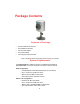
Package Contents Contents of Package: • • • • • One DCS-900 Internet Camera One Installation CD-ROM One AC power adapter One Camera Stand One Category 5 Ethernet Cable If any of the above items are missing, please contact your reseller.
Introduction Congratulations on your purchase of the DCS-900 Internet Camera! The DCS-900 is a versatile and unique solution for your small office or home. Unlike a PC Camera, the DCS-900 is a stand-alone system with a built-in CPU and Web server that transmits high quality video images for monitoring. The DCS-900 can be accessed remotely, and controlled from any PC/Notebook over the Intranet or Internet via a web browser.
Features & Benefits (continued) Web Configuration Using a standard Web browser, Administrators can configure and manage the Internet Camera directly from its own Web page via the Intranet or Internet.
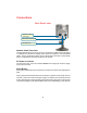
Connections Rear Panel view Ethernet Cable Connector DC Power Connector Reset Button Network Cable Connector The DCS-900 features an RJ-45 connector for connections to 10Base-T Ethernet cabling or 100Base-TX Fast Ethernet cabling (which should be Category 5 UTP twisted-pair cable). The port supports the NWay protocol, allowing the DCS-900 to automatically detect or negotiate the transmission speed of the network.
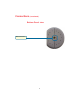
Connections (continued) Bottom Panel view Stand Connector 7
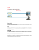
LEDS LED stands for Light-Emitting Diode. Front view Power LED LAN LED Power LED The Power LED is positioned on the right side of the DCS-900 lens. Steady green confirms that the DCS-900 is powered ON. Note: There are three settings for the Power LED for monitoring purposes: Normal / Off / Dummy. Please refer to the DCS-900 Camera Configuration section for detailed information and usage. LAN LED The LAN LED is positioned on the right side of the DCS-900’s lens. It is located below the Power LED.
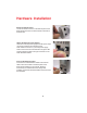
Hardware Installation Attach the Swivel Stand Locate the stand connector on the bottom panel of the DCS-900 and screw on the swivel stand to the base of the DCS-900. Attach the External Power Supply Attach the external power supply to the DC power input connector located on the rear panel of the DCS-900 and connect it to your local power supply. Note: Power source is confirmed when the green LED Power Indicator located to the right of the lens on the DCS-900 is illuminated.
Security To ensure the highest security and prevent unauthorized usage of the DCS-900, the Administrator has the exclusive privilege to authorize all users. The DCS-900 supports multi-level password protection/access to the DCS-900 that can be restricted by the Administrator for defined users who have a User Name and User Password. The Administrator can release a public User Name and Password so that when remote users access the DCS-900 they will be allowed to view the images transmitted by the DCS-900.
Using the Setup Wizard Follow the simple steps below to run the Setup Wizard to guide you quickly through the installation process. Insert the D-Link DCS-900 Driver CD into your CD-ROM drive. When the autorun screen appears, click Install Wizard to begin the installation.
Using the Setup Wizard (continued) Click Next Click Finish To run the Setup Wizard, click on Start->Programs->DCS-900 Series Setup Wizard. Your camera’s IP Address will be displayed here if it is valid.
Using the Setup Wizard (continued) You must change the Admin ID and Password immediately to protect your camera against unauthorized access. By default, the Admin ID and Password are blank. To change the Admin ID and Password, select both Change boxes and enter a New ID and New Password. Click Next The IP Address, Subnet Mask of your camera and Gateway must correspond with your network settings for you to access the camera.
DCS-900 Configuration Web Configuration After completing the Setup Wizard, you are ready to use your camera. The web configuration utility is designed to easily access and configure your DCS-900. From the Web Browser, enter the IP address that you assigned to your DCS-900 to access the Welcome screen of the DCS-900. Press Enter. Note: The PC’s IP address must correspond with the DCS-900’s IP address in the same segment (i.e. PC=192.168.0.5, Camera=192.168.0.20) for the two devices to communicate.
DCS-900 Configuration (continued) Configuration Click on Setup from the Home screen to access the settings required for the DCS-900.
DCS-900 Configuration (continued) Advanced > System The System menu allows you to configure and set up your DCS-900 for operation. If you already set up your camera using the Setup Wizard, you may view/change your settings here.
DCS-900 Configuration (continued) Advanced > System Camera Name: This field is used for entering a descriptive name for the camera. The default setting for the Camera Name is CS-xxxxxx, where xxxxxx are the last six digits of the MAC Address. The maximum length is 32 characters (Printable ASCII). Location: This field is used for entering a descriptive name for the location used by the DCS-900. IP Assignment: Important Information Access to the Internet Camera is gained by assigning a proper IP Address.
DCS-900 Configuration (continued) Advanced > System Assign Automatically Using Important This options is recommended only for advanced users and network administrators since it may be difficult to determine the IP Address of the unit after the IP Address has been automatically asssigned. It is recommended that an IP Address be assigned manually. If your network is using RARP, BOOTP, or DHCP Server you can Click Assign Automatically Using and click on RARP, BOOTP or DHCP.
DCS-900 Configuration (continued) Advanced > System The default setting for the LED control is Normal. When you have configured the LED control the correct illumination will be applied after 1 minute. Note: The three LED options allow the Administrator to customize the LEDs for discreet camera operation in surveillance scenarios. In Normal Mode, the LED indicator functions normally. Under Off Mode, the LED indicators are both OFF during active monitoring.
DCS-900 Configuration (continued) Advanced > System The Transfer Image Port must also be assigned a port number for multiple camera installation, beginning with Port 8482: Internet Camera 1 – IP 192.168.0.101, second Web Port 8482 Internet Camera 2 – IP 192.168.0.102, second Web Port 8483 Internet Camera 3 – IP 192.168.0.103, second Web Port 8484 Internet Camera 4 – IP 192.168.0.104, second Web Port 8485 Internet Camera 5 – IP 192.168.0.
DCS-900 Configuration (continued) Installing the DCS-900 Behind a Router Single Camera Installation If you are installing a single camera on your network the installation is an easy 4–step procedure: 1) 2) 3) 4) Identify Your Camera on the Network Assign a Local IP Address for Your Camera Determine Your Router’s WAN IP Address (Enable Remote Viewing) Open Virtual Server Ports for Your Router (Enable Remote Viewing) Multiple Camera Installation If you are installing multiple cameras on your network, the
DCS-900 Configuration (continued) Installing the DCS-900 Behind a Router 1) Identify Your Camera on the Network Once you are logged into the camera via a web browser on your network PC,click on the Advanced Tab, and select System. Enter a unique Camera Name and Location. These settings are important if you are installing several cameras on your network.
DCS-900 Configuration (continued) Installing the DCS-900 Behind a Router Assigning and opening second port in the DCS-900 ( For Installing Multiple Cameras) Opening ports will allow users to view the camera via the Internet. The ports that are opened must be unique for each camera in order to successfully view the images remotely. 3) Open Second Port The Open Second Port option is used when multiple cameras are being installed on a network OR for using a port other than the default port for image viewing.
DCS-900 Configuration (continued) Installing the DCS-900 Behind a Router ROUTER SET-UP AND INSTALLATION The following steps generally apply to any router that you have on your network. The D-Link DI-614+ is used as an example to clarify the configuration process. Your WAN IP Address information will be listed here. Determine Your Router’s WAN IP Address Note: Because a dynamic WAN IP can change from time to time depending on your ISP, you may want to obtain a Static IP address from your ISP.
DCS-900 Configuration (continued) Installing the DCS-900 Behind a Router ASSIGNING AND OPENING VIRTUAL SERVER PORTS 5) Open Virtual Server Ports To Enable Remote Image Viewing The Virtual Server Ports of your router must be opened for remote access to your camera. This is also referred to as port forwarding. Please proceed as follows: • Select Enabled to enable virtual server settings. • Enter your camera’s Local IP Address (Step d) in the Private IP field. • Select TCP under Protocol Type.
DCS-900 Configuration (continued) Installing the DCS-900 Behind a Router *IMPORTANT NOTE: Some ISPs may block access to port 80. Be sure to check with your ISP so that you can open the appropriate ports accordingly. Some ISPs block traffic on commonly used ports to conserve bandwidth. If your ISP does not pass traffic on port 80, you will need to change the service port the camera uses from 80 to something else, like 800.
DCS-900 Configuration (continued) Advanced > Video The Video menu allows you to control and adjust the image settings for your DCS-900. Click on Video on the left hand panel and the Image screen will appear as shown in the following illustration: Video Resolution: Select the desired video resolution format: 320x240 (default) or 640x480. Compression Rate: Select the desired compression rate ranging from very low to very high.
DCS-900 Configuration (continued) Advanced > Video Light Frequency: Adjust the light frequency to suit your area of operation. 50 Hz and 60 Hz variants are available to accommodate the different light frequencies found in USA (60 Hz) and Europe (50 Hz) for optimal image quality. Apply/Cancel: After making sure all your settings are correct, click on Apply to store the settings. You can alternatively click on Cancel to restore all settings to the values last saved to or retrieved from the DCS-900.
DCS-900 Configuration (continued) Tools > Admin Add User User Name: Enter the user name in this field. A maximum of 8 user names are allowed, however each user name must be different. Each user name can be used as a group. For example, if the User Name is Guest and the User Password is Guest, anyone can access the DCS-900 using this information. The maximum length for the User Name is 12 characters (Printable ASCII). User Password: Enter the user’s password you want to assign to the specific user-name.
DCS-900 Configuration (continued) Tools > Time The Time menu sets the DCS-900’s time and date requirements to provide correct information to users who are accessing from a remote site. The two options in the Time settings are Synchronized with Time Server or Set Manually. Click on Time in the left hand panel and this screen will appear as illustrated below: DateTime: Select Synchronized with Time Server and the time will be based on the GMT setting. This is the default setting for the DCS-900.
DCS-900 Configuration (continued) Tools > Time Protocol: Two options are available for linking with the Time Server. The default setting is NTP. TimeZone: The System administrator must select the time zone for the region. Please refer to the Appendix for the time zone selection table. To set the Time manually select Set Manually. The system administrator must then enter the Date and Time in the respective field manually.
DCS-900 Configuration (continued) Tools > Default The Default tab contains commands for restarting the DCS-900. Click on Tools, then the Default tab in the left hand panel and the Tools screen will appear as illustrated below Factory Reset: A factory reset restarts the DCS-900 and returns all settings to their default values. The Factory Reset panel contains the message “Do you really want to factory reset this device?” and a YES button.
DCS-900 Configuration (continued) Status Completing Your Camera Configuration Once the configuration is completed, click on Home to return to the Home screen and select the desired Viewing Image using either ActiveX Mode or Java Mode as described in the next section. The last step is to position the DCS-900 and adjust the focus, by manually turning the lens clockwise or counter-clockwise to the desired image quality.
DCS-900 Configuration (continued) ActiveX Date/Time - The date/time of the DCS-900 will be displayed according to your time server settings or from settings you have made manually. Note: Please refer to the Appendix for instructions on how to install ActiveX.
DCS-900 Configuration (continued) Java Camera Name - The Camera name will be displayed when the Camera Name field is changed in the Web Configuration setting under Advanced > System. Location - The location of the DCS-900 will be displayed when the Location field is changed in the Web Configuration settings under Advanced > System. Date/Time - The date/time of the DCS-900 will be displayed according to your time server settings or from your manual settings.
IPView Lite Application Installation Click Next Click Yes Click Next 36 (continued)
IPView Lite Application Installation (continued) Click Next Click Finish After successfully installing the IPView Lite, the application program for the DCS-900 is automatically installed to \Programs\IPView Directory. To start running the IPView Lite click on windows Start > Programs > IPViewLite > IPViewLite. Enter the default User Name: admin into the respective field and click on OK to log into the application.
IPView Lite Application Installation (continued) Once logged in, the IPView Lite application is executed and the IPView Lite interface will appear as follows in the default List View format: 38
IPView Lite - Getting Started This section describes the operation of the IPView Lite application User Interface with detailed procedures for using the application. IPView Lite IPView Lite allows you to manage your cameras by enabling you to search, configure and preview all the DCS-900s from one location. It is designed with a user-friendly interface for ease of control and navigation.
IPView Lite - Getting Started (continued) How to Change the Password Change Password When IPView Lite is used for the first time, it is highly recommended that the Administrator change the User Name and Password for security purposes. Once the User Name and Password are defined, only the Administrator has access to the management of IPView Lite applications. This procedure should be done as soon as possible to prevent unauthorized usage of the IPView Lite application.
IPView Lite - Getting Started (continued) How to Change the IP Address Changing the IP Address To change an IP Address for a camera, select Camera > Add. An Add Camera dialog box will appear (see below). Click on Browse. The Browse Camera dialog box will appear with a blank screen (see below).
IPView Lite- Getting Started (continued) How to Change the IP Address Click Search. IPView Lite will detect and search all the available cameras that are installed on the local area network (example below.) Highlight the camera you wish to change and click Change IP. If you have already chnaged the administrator user ID and password, you will be prompted to enter your admin ID and password before IPView Lite will allow you to change the IP Address for the DCS-900.
IPView Lite- Getting Started (continued) How to Add a Camera To add a new camera select Camera > Add from the IPView Lite. An Add Camera dialog box will appear. (See below.) Enter the IP Address of the camera in the specified field and click Add. If the IP Address is entered incorrectly or if you have a bad network connection, a dialog box will appear to notify you of the error. To add cameras in IPView Lite, check that you have your network configured correctly.
IPView Lite - Getting Started (continued) How to Add a Camera Click on Search. IPView Lite will detect and search for all the available cameras that are installed on the local area network. Highlight the camera you wish to add and click on Add. The Add Camera dialog box will appear once again with the IP Address entered. Click on Add. The camera will be automatically added into the IPView Lite list view format.
IPView Lite- Getting Started (continued) How to Add/Delete a Camera If the Login Camera dialog box appears, make sure to enter the correct User Name and Password. Click OK. The camera will be added into IPView Lite, in list format. If the User Name and Password are entered incorrectly, the camera will not be added into IPView Lite. The Login Camera dialog box will appear only if your have already set the User Name and Password during the Web Configuration setting.
IPView Lite- Getting Started (continued) How to Format the Camera view From the menu bar select View > 4 Cameras. You may also choose to view 1 camera on one screen. The viewing screen will appear with the video image. (See below.) The icon on the upper left corner of the screen will appear with the camera number that is being displayed. To return to the IPView Lite list view format, right-click on the icon located on the upper left corner of the screen and a case sensitive menu will appear.
IPView List - Getting Started (continued) How to Rotate the Video view In View Mode format, click on the icon located on the upper left corner of the screen and a pop-up menu will appear. Once you click Rotate Right or Rotate Left in the menu, the video will rotate 90 degrees to the right or left. How to take a Snap-Shot with the Camera To take a snap shot with the camera, you must highlight the camera you wish to use from the IPView Lite list view format. From the menu bar select Camera > Snap shot.
IPView Lite- Getting Started (continued) How to Start Recording To start recording with a camera you must highlight the camera you want to use from the list view format. From the menu bar select Camera > Start. An AVI file will appear in your IPView Lite folder to save the recorded videos. Alternatively, in the viewing mode (using either 1 or 4 cameras), right-click on the icon located on the upper left corner of the screen. A case sensitive menu will appear. Select the Start icon.
IPView Lite - Getting Started (continued) Camera Property Settings > General Once you have completed the initial configuration of the DCS-900 using the Web-based interface, you can review or change your configuration using either the Web-based configuration utility or the Property Settings in the DCS-900 IPView Lite. To access the Property Settings menu, select Camera > Property from the main menu. A dialog box will appear which allows for Web Configuration settings and upgrading firmware.
IPView Lite - Getting Started (continued) Camera Property Settings > IP Assignment IP Assignment If you need to change your IP Address, select the IP Address tab in the Camera property window. There are two options: Manually Assign or Assign Automatically Using. Please refer to theDCS-900 Configuration section: Advanced – System for further details.
IPView Lite - Getting Started (continued) Camera Property Settings > DNS DNS DNS (Domain Name System) server is an Internet service that translates domain names into IP Addresses. Please refer to the DCS-900 Configuration section under Advanced - System for further details.
IPView Lite- Getting Started (continued) Camera Property Settings > Misc, Image Misc Configure the LED Control, ActiveX control location, and second port in this menu. Please refer to the DCS-900 Configuration section under Advanced– System for further details. Image Brightness, contrast, hue, resolution, compression, frame rate, and light frequency can be adjusted for your camera. Please refer to the DCS-900 Configuration section under Advanced – Video for further details.
IPView Lite - Getting Started (continued) Camera Property Settings > Users Users Set up user accounts with user name and password for camera access. Please refer to the DCS-900 Configuration Setting under Tools-Admin for more detailed information. To add a user click on the Add icon and the Add User dialog box will appear. Enter the User Name and Password into the specific field. To delete a user, select the user and click Delete.
IPView Lite - Getting Started (continued) Camera Property Settings > Date/Time Date/Time Set the camera’s time and date to provide correct time information for remote users by selecting Synchronized with Time Server or Set Manually. Please refer to the DCS-900 Configuration section under Tools-Time for further details.
IPView - Getting Started (continued) Camera Property Settings > Information Information Displays information about the camera such as the model, firmware version, MAC address, and IP address. Please refer to the DCS-900 Configuration section under Status for further details.
IPView Lite- Getting Started (continued) Camera Property Settings > Tools Tools Reset the camera and update firmware in this section. Please refer to the DCS-900 Configuration section under Tools-Default for further details. Upgrade Firmware Enter the full path of the firmware binary file name in the Update Firmware field or you can click on the Browse button to select the file. Once the firmware file is entered click on the Update button to proceed with the update process. Once completed, click OK.
IPView Lite- Getting Started (continued) Camera Property Settings > Recording Recording Options Manual Recording If the Manual Recording option is chosen, you must manually start recording in the List view of the DCS-900 in the Menu Bar or by clicking on the Record Icon. Choose Round the Clock to enable the DCS-900 to record all video frames continuously to your hard drive. Larger files will be generated if Round-the-Clock Manual Recording is chosen.
IPView Lite- Getting Started (continued) Camera Property Settings > Recording Scheduled Recording Select Schedule Recording to record based on specific times and dates. Click Schedule Setting to set the time and date for recording your files. Select By Date and enter in the dates, Start, and Stop Times. The camera will start to record according to the specified date and time period entered. Select By Weekday to indicate specific days to record and the time period.
IPView Lite - Getting Started (continued) Camera Property Settings > Recording File Options You can adjust the maximum file size by clicking on By File Size from the Recording File Options field. The file size must be between 10 and 50MB. If the recorded video files reach the file size allocated, video images will be recorded into another file automatically. Be sure to click Apply to save your settings, then click OK to exit this screen.
IPView Lite- Getting Started (continued) Menu Bar The menu bar makes it easier to navigate IPView Lite. All Management functions can be accessed from the menu bar. Menu Bar > File New > Opens a new camera list. Cameras must then be added to the list for configuration Open > Opens saved camera lists. Save/Save As > Saves your current list of cameras and configurations. Exit > Exits the IPView Lite Application. .
IPView Lite - Getting Started (continued) Menu Bar > View View on the menu bar provides users with management capabilities for Columns, List, Camera and Refresh. You can view the Camera in 1 Camera or 4 Camera mode. The View menu bar is pictured below. Columns When Columns is launched, a dialog box will appear displaying the Column Settings. Select the columns that you wish to appear in the List View as illustrated below. Viewing Format You can view the format in List view.
IPView Lite- Getting Started (continued) List View All the cameras and their properties, such as the camera name, IP Address, user name, and location, will be displayed in the list view. Note: Right click on any camera to bring up a menu of actions you can apply to the selected camera. Double-clicking on the desired camera will bring up the Property dialog box. You can click the Refresh icon to update the camera list view.
IPView Lite- Getting Started (continued) Menu Bar > Camera, Tools Camera on the menu bar provides options to manage the camera. Add up to 4 additional Cameras for viewing. The Camera menu also allows you to Delete a camera, manage the Property, Enable real-time video capture, or take a Snap shot image. Enable Function By default, the video image is enabled. There will be a check next to the Enable command to show that the Enable function is working.
IPView Lite- Getting Started (continued) Menu Bar > Tools Account The account menu is for administrators to change user name and password. System Configuration . This menu allows you to set overwrite options to overwrite old recorded files with new recorded files. Check the Load Last Configuration When Program Starts to load all your configured settings each time you run IPView Lite. It is highly recommended that you select this option to save your camera settings in IPView Lite.
IPView Lite - Getting Started (continued) Menu Bar > Tools overwritten. You can specify between 500MB to 5GB hard drive reserve space. Click on By Time to overwrite old files with new files once the time frame that you specify has been reached. Clicking on By HDD Reserved Space allows new files to overwrite old files. You can reserve 500MB to 5GB HDD for the program. Click on By Time (Time: 1-240 Hours) to overwrite old files with new files once the time frame that you specify has been reached.
IPView Lite - Getting Started (continued) Menu Bar > Tools Networking Configuration If your LAN uses a Proxy server to connect to the Internet, select Use a proxy for HTTP Protocol, and click OK. If you choose this option, you must enter the IP address and port that your Proxy server uses to connect to the Internet. A Proxy server is a computer on your LAN that connects to the Internet without compromising the security of your internal network.
IPView Lite Icon Description Open a new file. The hot key is Ctrl+N. Open an existing file. The hot key is Ctrl+O. Save a file. The hot key is Ctrl+S. List view format. The hot key is Ctrl+F1. 1 Camera view format. The hot key is Ctrl+F3. 4 Camera view format. The hot key is Ctrl+F4. Refresh IPView Lite application. The hot key is F12. Add a camera. The hot key is Shift+Ins. Delete a camera. The hot key is Del. Property setting to configure the camera. The hot key is F2.
IPView Lite - Getting Started (continued) Context Sensitive Menu In List View format, highlight a camera and right-click to bring up a context sensitive menu for features such as Add, Delete, Property, Enable, and Snap shot and Start/ Stop recordings. In View mode format click on the icon located on the upper left corner of the screen and a case sensitive menu will appear (see below).
Uninstall IPView Application Click on windows Start Menu / Programs / IPView / Uninstall IPView. A new prompt screen will be displayed like the one below confirming the removal. Choose the option that you want and click Next to continue the process or click on Cancel to reject the uninstall process. After you click on Next, a Confirm Uninstall dialog box will appear. Click OK to continue the process.
Uninstall IPView Application (continued) The InstallShield Wizard prompt will appear. Click Finish to complete the uninstallation procedure.
Appendix A Frequently Asked Questions Internet Camera Features Q: What is an Internet Camera? A:The Internet Camera is a standalone system connecting directly to an Ethernet or Fast Ethernet network and supported by the wireless transmission based on the IEEE 802.11b standard. It is different from the conventional PC Camera, the Internet Camera is an all-in-one system with built-in CPU and web-based solutions providing a low cost solution that can transmit high quality video images for monitoring.
Frequently Asked Questions (continued) Internet Camera Installation Q: Can the Internet Camera be used outdoors? A: The Internet Camera is not weatherproof. It needs to be equipped with a weatherproof case to be used outdoors and it is not recommended. Q: What network cabling is required for the Internet Camera? A: The Internet Camera uses Category 5 UTP Twisted-pair cable allowing 10 Base-T and 100 Base-T networking.
Troubleshooting (continued) Internet Camera Installation A2: Another possible reason is the IP Address is located on a different subnet. To fix the problem, run the PING utility (follow the instructions in Appendix B - PING Your IP Address). If the utility returns “no response” or similar, the finding is probably correct, then you should proceed as follows: In Windows 98SE and 2000, check that the IP Address of the Internet Camera is within the same subnet as your workstation.
Troubleshooting (continued) Internet Camera Installation Q: Why does the Internet Camera work locally but not externally? A1: Might be caused from the firewall protection. Check the Internet firewall with your system administrator. The firewall may need to have some settings changed in order for the Internet Camera to be accessible outside your local LAN. A2: Make sure that the Internet Camera isn’t conflicting with any web server you may have running on your network.
Troubleshooting (continued) Q: The images are poor quality, how can I improve the image quality? A1: Make sure that your computers display properties are set to at least 15-bit color. Using 16 or 256 colors on your computer will produce dithering artifacts in the image, making the image look as if it has bad quality. A2: The configuration on the Internet Camera image display is incorrect.
How to Ping your IP Address (continued) Start a DOS window Start>Program>Accessories>Command Prompt Type ping x.x.x.x, where x.x.x.x is the IP Address of the Internet Camera. 1) A successful connection to the camera will be indicated by 4 reply statements (above). If you fail to connect to your camera you will see the following: 2) Check to see if you have entered your camera’s IP Address correctly or reassign yor camera’s IP Address.
Time Zone Table GMT stands for Greenwich Mean Time, which is the global time that all time zones are measured from.
Time Zone Table (continued) 78
Xplug Control Installation Installation to a Web Server Important Information It is highly recommended to install the Xplug Control application to the Web Server for Internet Explorer 5.0. It must be installed to a Public Domain with a Fixed IP Address. 1. Installation: Copy the “xplug.ocx” file to any Web Server table. Note the web address of the file location so that you can use it in the next step. 2.
Installation of the X-Plug to a Local PC (continued) Insert the CD-ROM into the CD-ROM drive to initiate the auto-run program. Once completed, a menu screen will appear as follows: To install Xplug Control click on the “Xplug Control” button to activate the installation procedure for the plugin program. Once executed a prompt will appear requesting the input of the desired language selection. Make the desired selection and click on “OK” to continue.
Installation of the X-Plug to a Local PC (continued) Click Next Click Yes 81
Installation of the X-Plug to a Local PC (continued) Click Finish Adjusting the Camera Focus To help you get the best image quality, keep in mind that while adjusting the DCS-900 focus you can preview the image quality from your Web browser.
Adjusting the Camera Focus (continued) Note: You can further adjust the Internet Camera’s image quality through the Web Configuration under Advanced-Video. Please refer to the Web Configuration section for further details. Warning Direct exposure to sunlight may cause permanent damage to the CMOS sensor. Therefore do not expose the Internet Camera’s lens directly to sunlight. When operation is required in glaring light environment, it is recommended to use an iris lens.
Technical Specifications Video specification Resolution: Sensor: Gain control: Exposure: White Balance: Shutter: Minimum Illumination: Focal Length: Aperture: 640 x 480 pixel 1/3" color CMOS sensor Automatic Automatic Automatic Electronics 1/60 ~ 1/15000 sec 2.5lux@f1.4, 3000K color 6.0 mm F=1.
Technical Specifications (continued) LED Indicator: Power LED (Green) LAN Activity LED (Orange) (Normal / Off / Dummy) Power Supply: Power Communication: DC 5V/2.5A, switching type 4.5 Watt (900mA x 5V) Communication Support Communication: Communication protocol: 10/100Mbps Ethernet and Fast Ethernet only HTTP, TCP/IP, UDP, ARP, ICMP, BOOTP, RARP, DHCP, PPPoE Web Configuration Requirements: • • • • • • Internet Explorer 5.0 or above or Netscape 6.
Contacting Technical Support You can find software updates and user documentation on the D-Link website. D-Link provides free technical support for customers within the United States and within Canada for the duration of the warranty period on this product. U.S. and Canadian customers can contact D-Link technical support through our website, or by phone. Tech Support for customers within the United States: D-Link Technical Support over the Telephone: (877) 453-5465 24 hours a day, seven days a week.
Warranty and Registration Subject to the terms and conditions set forth herein, D-Link Systems, Inc. (“D-Link”) provides this Limited warranty for its product only to the person or entity that originally purchased the product from: • • D-Link or its authorized reseller or distributor and Products purchased and delivered within the fifty states of the United States, the District of Columbia, U.S. Possessions or Protectorates, U.S. Military Installations, addresses with an APO or FPO.
Warranty and Registration (continued) • After an RMA number is issued, the defective product must be packaged securely in the original or other suitable shipping package to ensure that it will not be damaged in transit, and the RMA number must be prominently marked on the outside of the package. Do not include any or manuals accessories in the shipping package. D-Link will only replace the defective portion of Product and will not ship back any accessories.
Warranty and Registration (continued) Trademarks: D-Link is a registered trademark of D-Link Systems, Inc. Other trademarks or registered trademarks are the property of their respective manufacturers or owners. Copyright Statement: No part of this publication or documentation accompanying this Product may be reproduced in any form or by any means or used to make any derivative such as translation, transformation, or adaptation without permission from D-Link Corporation/D-Link Systems, Inc.