Preface D-Link reserves the right to revise this publication and to make changes in the content hereof without obligation to notify any person or organization of such revisions or changes. Trademarks D-Link and the D-Link logo are trademarks or registered trademarks of D-Link Corporation or its subsidiaries in the United States or other countries. All other company or product names mentioned herein are trademarks or registered trademarks of their respective companies.
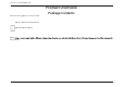
Section 1 - Product Overview Product Overview Package Contents Check for the supplied accessories below: DIR-513 Wireless N Pocket Router Quick Installation Guide Note: this product.
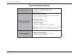
Section 1 - Product Overview System Requirements Network Requirements X I "OC@MI@O =GD@ION X "OC@MI@O Computer with the following: X 4DI?JRN] *<>DIOJNC JM )DIPS =
Section 1 - Product Overview Features t Internet Connectivity - In conjunction with a DSL or Cable Modem, this device provides high-speed Internet connectivity to your local network for up to four wired devices. t Wireless LAN functionality - This router supports features like WMM, RF Output Level Control, WPS, and much more. t Networking - This router comes with one WAN port and four LAN ports that enable up to four computers on your local network to be connected.
Section 2 - Hardware Installation Wireless Installation Considerations The router lets you access your network using a wireless connection from virtually anywhere within the operating range of your wireless network. Keep in mind, however, that the number, thickness and location of walls, ceilings, or other objects that the wireless signals must pass through, may limit the range. Ranges vary depending on the types of materials and background RF (radio frequency) noise in your home or office.
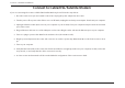
Section 2 - Hardware Installation Connect to Cable/DSL/Satellite Modem If you are connecting the router to a Cable/DSL/Satellite Modem, please follow the steps below: 1. Place the router in an open and central location. Do not plug the power adapter into the router. 2. Turn the power off on your modem. If there is no on/off switch, unplug the modem’s power adapter. Shut down your computer. 3.
Section 3 - Software Configuration Configuration This section will show you how to configure your new D-Link wireless router using the web-based configuration utility. Web-based Configuration Utility To access the configuration utility, open a web browser such as Internet Explorer and enter the IP address of the router (192.168.0.1). You may also connect using the NetBIOS name in the address bar (http://dlinkrouter). Enter your password. Admin is the default username and cannot be changed.
Section 3 - Software Configuration Setup Wizard Internet Connection Click Internet Connection Setup Wizard to quickly configure your router. Skip to the next page. If you want to enter your settings without running the wizard, click Manual Configuration and skip to page 20.
Section 3 - Software Configuration Internet Connection(Setup Wizard) When configuring the router for the first time, we recommend that you click Internet Connection Setup Wizard, and follow the instructions on the screen. This wizard is designed to assist user with a quick and easy method to configure the Internet connection of this router. Anytime during the Internet Connection Setup Wizard, you can click on Cancel to discard any changes made and return to the main Internet page.
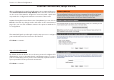
Section 3 - Software Configuration Step 2: Select Your Time Zone Select the appropriate time zone for your location. This information is required to configure the time-based options for the router. Click Next to continue. Step 3: Internet Connection Here the user will be able to configure the Internet Connectivity used by this device. If your ISP connection is listed in the drop-down menu select it and click Next.
Section 3 - Software Configuration Step 3: Internet Connection (Dynamic IP Address) After selecting the Dynamic IP Address Internet connection method, the following page will appear. MAC Address: Enter the MAC address of the Internet gateway (plugged into the Internet port of this device). Clone Button: If the configuration PC also acts as the Internet gateway, then click on the Clone Your PC’s MAC Address button to copy the PC’s MAC address into the space provided.
Section 3 - Software Configuration Step 3: Internet Connection (PPPoE) After selecting the PPPoE Internet connection method, the following page will appear: Address Mode: The user can specify whether this Internet connection requires the use of a Dynamic or Static IP address. PPPoE usually requires a Dynamic IP configuration. IP Address: Enter the PPPoE IP address used. This option is only available if Static IP is selected. User Name: Enter the PPPoE account user name used.
Section 3 - Software Configuration Step 3: Internet Connection (PPTP) After selecting the PPTP Internet connection method, the following page will appear: Address Mode: Here the user can specify whether this Internet connection requires the use of a Dynamic or Static IP address. PPTP usually requires a Dynamic IP configuration. PPTP IP Address: Enter the PPTP IP address used here. This option is only available if Static IP is selected. PPTP Subnet Enter the PPTP Subnet Mask used.
Section 3 - Software Configuration Step 3: Internet Connection (L2TP) After selecting the L2TP Internet connection method, the following page will appear: Address Mode: Here the user can specify whether this Internet connection requires the use of a Dynamic or Static IP address. L2TP usually requires a Dynamic IP configuration. L2TP IP Address: Enter the L2TP IP address used here. This option is only available if Static IP is selected. L2TP Subnet Enter the L2TP Subnet Mask used.
Section 3 - Software Configuration Step 3: Internet Connection (Static IP Address) After selecting the Static IP Address Internet connection method, the following page will appear: IP Address: Subnet Mask: Gateway Address: Primary DNS Address: Secondary DNS Address: Enter the Static IP address provided by the ISP. Enter the Subnet Mask provided by the ISP. Enter the Gateway IP address provided by the ISP. Enter the Primary DNS IP address used. Enter the Secondary DNS IP address used.
Section 3 - Software Configuration Manual Configuration On this page the user can configure the Internet Connection settings manually. To access the Manual Internet Connection Setup page, click on the Manual Internet Connection Setup button. On this page there are multiple parameters that can be configured regarding the Internet Connection setup. We’ll discuss them from top to bottom. At any given point the user can save the configuration done by clicking on the Save Settings button.
Section 3 - Software Configuration Secondary DNS: Enter the Secondary DNS IP address used. This field is normally optional. Only one DNS address is required for a functional Internet connection, but using a second DNS address provides more stability. MTU: Maximum Transmission Unit - you may need to change the MTU for optimal performance with your specific ISP. 1500 is the default MTU. MAC Address: The default MAC Address is set to the Internet port’s physical interface MAC address on the Broadband Router.
Section 3 - Software Configuration My Internet Connection is: PPPoE (Username/Password) Another Internet Connection type is PPPoE. This option is typically used if you have a DSL Internet Connection. Make sure to remove the PPPoE software installed on your computer first before using this connection type. Most of the information needed for this connection type is provided to you by your ISP.
Section 3 - Software Configuration Secondary DNS Enter the Secondary DNS IP address used here. This field is normally optional. Only one DNS address is required for a functional Server: Internet connection, but using a second DNS address provides more stability. MTU: Maximum Transmission Unit - you may need to change the MTU for optimal performance with your specific ISP. 1492 is the default MTU.
Section 3 - Software Configuration My Internet Connection is: PPTP (Username/Password) Another Internet Connection type is PPTP. This option is typically used if you have a secure DSL Internet Connection. Most of the information needed for this connection type is provided to you by your ISP. Address Mode: Here the user can specify whether this Internet connection requires the use of a Dynamic or Static IP address. PPTP usually requires a Dynamic IP configuration.
Section 3 - Software Configuration Maximum Idle Time: Primary DNS Server: Secondary DNS Server: MTU: Enter a maximum idle time during which the Internet connection is maintained during inactivity. To disable this feature, enable Auto-reconnect. Enter the Primary DNS IP address used. Enter the Secondary DNS IP address used. This field is normally optional. Only one DNS address is required for a functional Internet connection, but using a second DNS address provides more stability.
Section 3 - Software Configuration Address Mode: The user can specify whether this Internet connection requires the use of a Dynamic or Static IP address. L2TP usually requires a Dynamic IP configuration. L2TP IP Address: Enter the L2TP IP address used. This option is only available if Static IP is selected. L2TP Subnet Enter the L2TP Subnet Mask used. Mask: L2TP Gateway IP Enter the L2TP Gateway IP address used. Address: L2TP Server IP Enter the L2TP Server IP address used.
Section 3 - Software Configuration MTU: Maximum Transmission Unit - you may need to change the MTU for optimal performance with your specific ISP. 1400 is the default MTU. MAC Address: The default MAC Address is set to the Internet port’s physical interface MAC address on the Broadband Router. It is not recommended that you change the default MAC address unless required by your ISP.
Section 3 - Software Configuration My Internet Connection is: DS-Lite) Another Internet Connection type is DS-Lite. After selecting DS-Lite, the following parameters will be available for configuration: DS-Lite Select the DS-Lite DHCPv6 Option to let the router Configuration: allocate the AFTR IPv6 address automatically. Select the Manual Configuration to enter the AFTR IPv6 address in manually.
Section 3 - Software Configuration Wireless Settings On this page the user can configure the Wireless settings for this device. There are 3 ways to configure Wireless using this router. Firstly, the user can choose to make use for the quick and easy Wireless Connection Setup Wizard. Secondly, the user can choose to make use Wi-Fi Protected Setup. Lastly, the user can configure the Wireless settings manually.
Section 3 - Software Configuration Step 2: This step will only be available if the user selected ‘Manually assign a network key’ in the previous step. Here the user can manually enter the WPA/WPA2 pre-shared key in the Wireless Security Password space provided. The key entered must be between 8 and 63 characters long. Remember, this key will be used when wireless clients wants to connect to this device. So please remember this key to prevent future troubleshooting.
Section 3 - Software Configuration Wireless Settings: Wi-Fi Protected Setup Wizard If your Wireless Clients support the WPS connection method, this Wi-Fi Protected Setup Wizard can be used to initiate a wireless connection between this device and Wireless clients with a simple click of the WPS button. The Wi-Fi Protected Setup Wizard is specially designed to assist basic network users with a simple, step-by-step set of instructions to connect wireless clients to this router using the WPS method.
Section 3 - Software Configuration Step 2: After selecting Manual, the following page will appear. On this page to user can view the wireless configuration of this router. The wireless clients should configure their wireless settings to be identical to the settings displayed on this page for a successful connection. This option is for wireless clients that can’t use the WPS method to connect to this device. Click on the Prev button to return to the previous page.
Section 3 - Software Configuration The following parameters will be available for wireless distribution system (WDS) configuration: Enable WDS: Check the box to enable the WDS function. If you do not want to use WDS, uncheck the box to disable the service. Select the time frame that you would like your WDS enabled. The schedule may be set to Always. Any schedule you create will be available in the drop-down menu. Click New Schedule to create a new schedule.
Section 3 - Software Configuration The following parameters will be available for configuration: Wireless Band: Displays the wireless band being configured. In this option we find that the following parameters will be regarding the 2.4GHz band. Enable Wireless: Check the box to enable the wireless function. If you do not want to use wireless, uncheck the box to disable all the wireless functions. Select the time frame that you would like your wireless network enabled. The schedule may be set to Always.
Section 3 - Software Configuration By default the wireless security of this router will be disabled. In this next option the user can enabled or disable wireless security for the frequency band 2.4GHz. There are two types of encryption that can be used- WEP or WPA/WPA2. Wireless Security Mode: WEP Wired Equivalent Privacy (WEP) is the most basic form of encryption that can be used for wireless networks. Even though it is known as a ‘weak’ security method, it is better than no security at all.
Section 3 - Software Configuration Wireless Security Mode: WPA-Personal Wi-Fi Protected Access (WPA) is the most advanced and up to date wireless encryption method used today. This is the recommended wireless security option. WPA supports two authentication frameworks. Personal (PSK) and Enterprise (EAP). Personal requires only the use of a pass-phrase (Shared Secret) for security.
Section 3 - Software Configuration Wireless Security Mode: WPA-Enterprise Wi-Fi Protected Access (WPA) is the most advanced and up to date wireless encryption method used today. This is the recommended wireless security option. WPA supports two authentication frameworks. Personal (PSK) and Enterprise (EAP). Personal requires only the use of a pass-phrase (Shared Secret) for security.
Section 3 - Software Configuration Network Settings On this page the user can configure the internal network settings of the router and also able to configure the built-in DHCP server to assign IP addresses to computers on the network. The IP address that is configured here is the IP address that is used to access the Web-based management interface. If you change the IP address in this section, you may need to adjust your PC’s network settings to access the network again.
Section 3 - Software Configuration The following parameters will be available for configuration: Enable DHCP Check this box to enable the DHCP server on your Server: router. Uncheck to disable this function. DHCP IP Address Enter the starting and ending IP addresses for the Range: DHCP server’s IP assignment. DHCP Lease The length of time for the IP address lease. Enter Time: the Lease time in minutes.
Section 3 - Software Configuration NetBIOS node This field indicates how network hosts are to perform NetBIOS name registration and discovery. H-Node, this indicates a Hybridtype: State of operation. First WINS servers are tried, if any, followed by local network broadcast. This is generally the preferred mode if you have configured WINS servers. M-Node (default), this indicates a Mixed-Mode of operation.
Section 3 - Software Configuration Add/Edit DHCP Reservation This option lets you reserve IP addresses, and assign the same IP address to the network device with the specified MAC address any time it requests an IP address. This is almost the same as when a device has a static IP address except that the device must still request an IP address from the D-Link router. The D-Link router will provide the device the same IP address every time.
Section 3 - Software Configuration IPv6 On this page, the user can configure the IPv6 Connection type. There are two ways to set up the IPv6 Internet connection. You can use the Webbased IPv6 Internet Connection Setup Wizard, or you can manually configure the connection.
Section 3 - Software Configuration Step 1: Configure Your IPv6 Internet Connection The router will try and detect whether its possible to obtain the IPv6 Internet Connection type automatically. If this succeeds then the user will be guided through the input of the appropriate parameters for the connection type found.
Section 3 - Software Configuration Step 1: Configure Your IPv6 Internet Connection There are several connection types to choose from. If you are unsure of your connection method, please contact your IPv6 Internet Service Provider. Note: If using the PPPoE option, you will need to ensure that any PPPoE client software on your computers has been removed or disabled. The 3 options available on this page is IPv6 over PPPoE, Static IPv6 address and Route, and Tunneling Connection.
Section 3 - Software Configuration Set Static IPv6 Address Connection This mode is used when your ISP provides you with a set IPv6 addresses that does not change. The IPv6 information is manually entered in your IPv6 configuration settings. You must enter the IPv6 address, Subnet Prefix Length, Default Gateway, Primary DNS Server, and Secondary DNS Server. Your ISP provides you with all this information.
Section 3 - Software Configuration Tunneling Connection (6rd) After selecting the Tunneling Connection (6rd) option, the user can configure the IPv6 6rd connection settings. The following parameters will be available for configuration: 6rd IPv6 Prefix: Enter the 6rd IPv6 address and prefix value used here. IPv4 Address: Enter the IPv4 address used here. Mask Length: Enter the IPv4 mask length used here. Assigned IPv6 Displays the IPv6 assigned prefix value here.
Section 3 - Software Configuration Manual IPv6 Internet Connection Option For the advanced user that have configured a router before, click on the Manual IPv6 Internet Connection Setup button to input all the settings manually. On this page the user can manually configure the mode that the Router will use to access an IPv6 Internet connection. There are several connection types to choose from: Link-local, Static IPv6, DHCPv6, Stateless Auto-Configuration, PPPoE, IPv6 over IPv4 Tunnel and 6to4.
Section 3 - Software Configuration Use the section to configure the internal network settings of your router. The LAN IPv6 Link-Local Address is the IPv6 Address that you use to access the Web-based management interface. If you change the LAN IPv6 Address here, you may need to adjust your PC’s network settings to access the network again. DHCP-PD can be used to acquire a IPv6 prefix for the LAN interface. Enable DHCPPD: LAN IPv6 Address: LAN IPv6 LinkLocal Address: Select this option to enable DHCP PD.
Section 3 - Software Configuration IPv6 Address This option is only available when the autoRange (Start): configuration type is set to Stateful. Enter the start IPv6 Address for the DHCPv6 range for your local computers. IPv6 Address This option is only available when the autoRange (End): configuration type is set to Stateful. Enter the end IPv6 Address for the DHCPv6 range for your local computers. IPv6 Address This option is only available when the autoLifetime: configuration type is set to Stateful.
Section 3 - Software Configuration IPv6 Connection Type: Static IPv6 In the following section we’ll discuss the parameters that can be configured when setting up an Static IPv6 connection. This mode is used when your ISP provides you with a set IPv6 addresses that does not change. The IPv6 information is manually entered in your IPv6 configuration settings. You must enter the IPv6 address, Subnet Prefix Length, Default Gateway, Primary DNS Server, and Secondary DNS Server.
Section 3 - Software Configuration The following parameters will be available for configuration: LAN IPv6 Enter the LAN (local) IPv6 address for the router Address: here. LAN IPv6 Link- Displays the Router’s LAN Link-Local Address here. Local Address: The following parameters will be available for configuration: Enable Automatic The user can tick this option to enable the autoIPv6 address: configuration feature. Autoconfiguration The user can select the auto-configuration type Type: used here.
Section 3 - Software Configuration IPv6 Connection Type: Autoconfiguration (SLAAC/DHCPv6) In the following section we’ll discuss the parameters that can be configured when setting up an Autoconfiguration (SLAAC/DHCPv6) connection. This is a method of connection where the ISP assigns your IPv6 address when your router requests one from the ISP’s server. Some ISP’s require you to make some settings on your side before your router can connect to the IPv6 Internet.
Section 3 - Software Configuration The following parameters will be available for configuration: Enable Automatic The user can tick this option to enable the autoIPv6 address: configuration feature. Enable Automatic Tick this option to enable the automatic DHCPDHCP-PD in LAN: PD on the LAN. Autoconfiguration The user can select the auto-configuration type Type: used here. Router This option is only available when the autoAdvertisement configuration type is set to Stateless.
Section 3 - Software Configuration IPv6 Connection Type: PPPoE Select this option if your ISP requires you to use a PPPoE (Point to Point Protocol over Ethernet) connection to IPv6 Internet. DSL providers typically use this option. This method of connection requires you to enter a Username and Password (provided by your Internet Service Provider) to gain access to the IPv6 Internet. The supported authentication protocols are PAP and CHAP.
Section 3 - Software Configuration The following parameters will be available for configuration: Obtain IPv6: Select this option to obtain the DNS Server addresses automatically. Use IPv6: Select this option to manually enter the DNS Server addresses used. Primary DNS: Enter the primary DNS Server address used here. Secondary DNS: Enter the secondary DNS Server address used here. The following parameters will be available for configuration: Enable DHCP- Select this option to enable DHCP PD.
Section 3 - Software Configuration The following parameters will be available for configuration: Enable Automatic The user can tick this option to enable the IPv6 address: auto-configuration feature. Enable Automatic Tick this option to enable the automatic DHCPDHCP-PD in LAN: PD on the LAN. Autoconfiguration The user can select the auto-configuration Type: type used here. Router This option is only available when the autoAdvertisement configuration type is set to Stateless.
Section 3 - Software Configuration IPv6 Connection Type: IPv6 in IPv4 Tunnel In section to the user can configure the IPv6 connection to run in IPv4 Tunnel mode. IPv6 over IPv4 tunneling encapsulates IPv6 packets in IPv4 packets so that IPv6 packets can be sent over an IPv4 infrastructure. The following parameters will be available for configuration: Remote IPv4 Enter the remote IPv4 address used here. Address: Remote IPv6 Enter the remote IPv6 address used here.
Section 3 - Software Configuration The following parameters will be available for configuration: Enable DHCP- Select this option to enable DHCP PD. PD: LAN IPv6 Enter the LAN IPv6 address used here. This address Address: must be in the ‘/64’ subnet. LAN IPv6 Link- Displays the LAN IPv6 Link-Local address used Local Address: here. The following parameters will be available for configuration: Enable Automatic The user can tick this option to enable the autoIPv6 address: configuration feature.
Section 3 - Software Configuration IPv6 Connection Type: 6to4 In this section the user can configure the IPv6 6to4 connection settings. 6to4 is an IPv6 address assignment and automatic tunneling technology that used to provide unicast IPv6 connectivity between IPv6 sites and hosts across the IPv4 Internet. The following parameters will be available for configuration: 6to4 Address: Here the 6to4 configured address will be displayed. 6to4 Relay: Enter the 6to4 relay address used here.
Section 3 - Software Configuration The following parameters will be available for configuration: Enable Automatic The user can tick this option to enable the autoIPv6 address: configuration feature. Autoconfiguration The user can select the auto-configuration type Type: used here. IPv6 Address This option is only available when the autoRange (Start): configuration type is set to Stateful. Enter the start IPv6 Address for the DHCPv6 range for your local computers.
Section 3 - Software Configuration IPv6 Connection Type: 6rd In this section the user can configure the IPv6 6rd connection settings. The following parameters will be available for configuration: 6rd Select the desired 6rd configuration option here. Configuration: 6rd IPv6 Prefix: Enter the 6rd IPv6 address and prefix value used here. IPv4 Address: Enter the IPv4 address used here. Mask Length: Enter the IPv4 mask length used here. Assigned IPv6 Displays the IPv6 assigned prefix value here.
Section 3 - Software Configuration The following parameters will be available for configuration: Enable Automatic The user can tick this option to enable the autoIPv6 address: configuration feature. Autoconfiguration The user can select the auto-configuration type Type: used here. Router This option is only available when the autoAdvertisement configuration type is set to Stateless. Enter the Lifetime: router advertisement lifetime value used here.
Section 3 - Software Configuration IPv6 Connection Type: Local Connection Only The Link-local address is used by nodes and routers when communicating with neighboring nodes on the same link. This mode enables IPv6capable devices to communicate with each other on the LAN side. The following parameters will be available for configuration: LAN IPv6 Link- Displays the LAN IPv6 Link-Local address used Local Address: here. Click on the Save Settings button to accept the changes made.
Section 3 - Software Configuration Advanced Category This section allows the user to configure the more advanced features that can be done by this router. Features like Port Forwarding, Firewall settings, Quality of Service settings and more.
Section 3 - Software Configuration Virtual Server This router can be configured as a virtual server so that remote users accessing Web or FTP services via the public IP address can be automatically redirected to local servers in the LAN (Local Area Network). The router’s firewall feature filters out unrecognized packets to protect the LAN network so all computers networked with the router are invisible to the outside world.
Section 3 - Software Configuration Port: Enter the port that you want to open next to Public Port and Private Port. The public and private ports are usually the same. The public port is the port seen from the Internet side, and the private port is the port being used by the application on the computer within your local network. Traffic Type: Select TCP, UDP, or All from the Protocol drop-down menu. Schedule: Use the drop-down menu to schedule the time that the Virtual Server Rule will be enabled.
Section 3 - Software Configuration Port Forwarding The Port Forwarding option gives Internet users access to services on your LAN. This feature is useful for hosting online services such as FTP, Web or game servers. For each entry, you define a public port on your router for redirection to an internal LAN IP Address and LAN port. This option is used to open multiple ports or a range of ports in your router and redirect data through those ports to a single PC on your network.
Section 3 - Software Configuration Application Rules Some applications require multiple connections, such as Internet gaming, video conferencing, Internet telephony and others. These applications have difficulties working through NAT (Network Address Translation). Special Applications makes some of these applications work with the router.
Section 3 - Software Configuration QoS Engine The QoS Engine option helps improve your network gaming performance by prioritizing applications. By default the QoS Engine settings are disabled and application priority is not classified automatically. The QoS section contains a queuing mechanism, traffic shaping and classification. It supports two kinds of queuing mechanisms. Strict Priority Queue (SPQ) and Weighted Fair Queue (WFQ). SPQ will process traffic based on traffic priority.
Section 3 - Software Configuration After specifying the QoS framework used, in the QoS setup section, the user can now create individual rules for scenarios that require the use of traffic control and data priority manipulation. The following parameters will be available for configuration: Checkbox: Tick this option to enable the rule specified. Name: Enter a custom name for the rule being created here. This name is used for identification.
Section 3 - Software Configuration Network Filter The MAC (Media Access Controller) Address filter option is used to control network access based on the MAC Address of the network adapter. A MAC address is a unique ID assigned by the manufacturer of the network adapter. This feature can be configured to ALLOW or DENY network/ Internet access. In the MAC Filtering Rules section, the user can create and edit Network filter rules. This maximum amount of rules that can be created are 24 rules.
Section 3 - Software Configuration Access Control The Access Control option allows you to control access in and out of your network. Use this feature as Access Controls to only grant access to approved sites, limit web access based on time or dates, and/or block internet access for applications like P2P utilities or games. The following parameters will be available for configuration: Enable Access Tick this option to enable the Access Control Control: feature.
Section 3 - Software Configuration Step 2: In the second step, the user can configure the schedule settings for this rule. The following parameters will be available for configuration: Details: Select the appropriate predefined schedule rule to apply to this rule from the drop-down menu. Step 3: In the third step, the user can configure the address type and IP address of the machines used in this rule.
Section 3 - Software Configuration The following parameters will be available for configuration: Apply Web Filter: After selecting the ‘Block Some Access’ option, the user will be able to select this option. Selecting this option will allow the web filter access control feature to be applied to this rule. Apply Advanced After selecting the ‘Block Some Access’ option, Port Filters: the user will be able to select this option.
Section 3 - Software Configuration Website Filter Website Filters are used to allow you to set up a list of Web sites that can be viewed by multiple users through the network. Website Filter is used to allow or deny computers on your network from accessing specific web sites by keywords or specific Domain Names. Select ‘ALLOW computers access to ONLY these sites’ in order only allow computers on your network to access the specified URLs and Domain Names.
Section 3 - Software Configuration Inbound Filter The Inbound Filter option is an advanced method of controlling data received from the Internet. With this feature you can configure inbound data filtering rules that control data based on an IP address range. Inbound Filters can be used for limiting access to a server on your network to a system or group of systems. Filter rules can be used with Virtual Server, Port Forwarding, or Remote Administration features.
Section 3 - Software Configuration Firewall Settings A firewall protects your network from the outside world. The router offers a firewall type functionality. The SPI feature helps prevent cyber attacks. Sometimes you may want a computer exposed to the outside world for certain types of applications. If you choose to expose a computer, you can enable DMZ. DMZ is short for Demilitarized Zone. This option will expose the chosen computer completely to the outside world.
Section 3 - Software Configuration Firewall rules can be used to allow or deny traffic passing through the router. You can specify a single port by utilizing the input box at the top or a range of ports by utilizing both input boxes. DMZ means “Demilitarized Zone”. DMZ allows computers behind the router firewall to be accessible to Internet traffic. Typically, your DMZ would contain Web servers, FTP servers and others.
Section 3 - Software Configuration Routing The Routing option is an advanced method of customizing specific routes of data through your network. In the Routing List section, the user can configure routing rules used by this router. The maximum amount of rules that can be configured is 32. The following parameters will be available for configuration: Checkbox: To enable a route, check the box that is on the left side of the route. Name: Enter a name for the rule used here.
Section 3 - Software Configuration Advanced Wireless These options are for users that wish to change the behavior of their 802.11n wireless radio from the standard settings. We do not recommend changing these settings from the factory defaults. Incorrect settings may impact the performance of your wireless radio. The default settings should provide the best wireless radio performance in most environments.
Section 3 - Software Configuration Wi-Fi Protected Setup Wi-Fi Protected Setup (WPS) System is a simplified method for securing your wireless network during the “Initial setup” as well as the “Add New Device” processes. The Wi-Fi Alliance (WFA) has certified it across different products as well as manufactures. The process is just as easy, as depressing a button for the Push-Button Method or correctly entering the 8-digit code for the Pin-Code Method.
Section 3 - Software Configuration Step 1: In this step the user have two options to choose from. You can choose Auto if the wireless client supports WPS, or Manual if the wireless client does not support WPS. Click on the Prev button to return to the previous page. Click on the Next button to continue to the next page. Click on the Cancel button to discard the changes made and return to the main wireless page. Step 2: After selecting Auto, the following page will appear.
Section 3 - Software Configuration Advanced Network This section contains settings which can change the way the router handles certain types of traffic. We recommend that you not change any of these settings unless you are already familiar with them or have been instructed to change them by one of our support personnel. UPnP UPnP is short for Universal Plug and Play which is a networking architecture that provides compatibility among networking equipment, software, and peripherals.
Section 3 - Software Configuration Multicast Streams This section enables the user to allow IPv4 or IPv6 Multicast traffic to pass from the Internet to your network more efficiently. The following parameters will be available for configuration: IPv4 Enable Multicast Streams Enable IPv6 Multicast Streams Enable this option if you are receiving video on demand type of service from the Internet.
Section 3 - Software Configuration Tools Category In this category the user will be able to configure features that are related to the router itself. Features like the time settings, login accounts, firmware update and more.
Section 3 - Software Configuration Admin This page will allow you to change the Administrator password and configure the authentication settings. This window also allows you to enable Remote Management, via the Internet. For security reasons, it is recommended that you change the password for the Admin and User accounts. Be sure to write down the new password to avoid having to reset the router in case they are forgotten.
Section 3 - Software Configuration Enable Remote Tick this option to enable remote management. Management: This option will enable the router to be accessible from the Internet port. Remote Admin Enter the remote administration port number used here. Sometimes services like an internal web server will occupy the port Port: number 80. In this option the user can change the remote administration port to 8080 for example. Remote Admin Select the appropriate remote admin inbound filter behavior here.
Section 3 - Software Configuration Time The Time window allows you to configure, update, and maintain the correct time on the internal system clock. From this section you can set the time zone that you are in and set the Time Server. Daylight Saving can also be configured to automatically adjust the time when needed. Time and Date Configuration Here the user can configure the time zone as well as the daylight savings settings used for this router.
Section 3 - Software Configuration Set the Time and Date Manually Here the user can configure the time and date values, used by this router, manually. Here the user can also synchronize the router’s time with the configuration computer’s time. The following parameters will be available for configuration: Set Manually: Here the user can manually configure the date and time used by this device. Options to configure are Year, Month, Day, Hour, Minute, and Second.
Section 3 - Software Configuration Email Settings The Email feature can be used to send the system log files and router alert messages to your email address. Email Notification When this option is enabled, router activity logs or firmware upgrade notifications can be emailed to a designated email address. The following parameters will be available for configuration: Enable Email Tick this option to enable the Email notification Notification: feature.
Section 3 - Software Configuration Account Name: Enter your account for sending email. Password: Enter the password associated with the account. Verify Password: Re-enter the password associated with the account here. Send Mail Now: Click this button to send a test email from the Router to verify that the email settings have been configured correctly. Email Log When Full or on Schedule Normally emails are sent at the starting and ending time defined in the schedule.
Section 3 - Software Configuration System This section allows you to manage the router’s configuration settings, reboot the router, and restore the router to the factory default settings. Restoring the unit to the factory default settings will erase all settings, including any rules that you’ve created.
Section 3 - Software Configuration Firmware Use the Firmware window to upgrade the firmware of the Router and install language packs. If you plan to install new firmware, make sure the firmware you want to use is on the local hard drive of the computer. If you want to install a new language pack, make sure that you have the language pack available. Please check the support site for firmware updates. You can download firmware upgrades to your hard drive from the support site.
Section 3 - Software Configuration Dynamic DNS The DDNS feature allows you to host a server (Web, FTP, Game Server, etc…) using a domain name that you have purchased (www. whateveryournameis.com) with your dynamically assigned IP address. Most broadband Internet Service Providers assign dynamic (changing) IP addresses. Using a DDNS service provider, your friends can enter in your domain name to connect to your server no matter what your IP address is.
Section 3 - Software Configuration The following parameters will be available for configuration: Enable: Tick this option to enable the Dynamic DNS feature for IPv6 hosts. IPv6 Address: Enter the IPv6 Address used here. Alternatively, the user can select the Computer Name for the drop-down list and click on the << button to add it the IPv6 Address field. Host Name: Enter the IPv6 host name used for the DDNS account here. Click on the Save button to add the IPv6 host to the IPv6 Dynamic DNS List.
Section 3 - Software Configuration In the IPv6 Dynamic DNS List section, a list of IPv6 hosts will be displayed. Tick the Enable checkbox to make the host active. To edit a icon. To remove a specific entry, click on specific entry click on the icon. the Click on the Save Settings button to accept the changes made. Click on the Don’t Save Settings button to discard the changes made.
Section 3 - Software Configuration System Check This useful diagnostic utility can be used to check if a computer is on the Internet. It sends ping packets and listens for replies from the specific host. In the Ping Test section the user can test the Internet connectivity by entering in a host name or the IP address that you want to Ping and click on the Ping button. The status of your Ping attempt will be displayed in the Ping Result box.
Section 3 - Software Configuration Schedules Schedules can be created for use with enforcing rules. For example, if you want to restrict web access to Mon-Fri from 3pm to 8pm, you could create a schedule selecting Mon, Tue, Wed, Thu, and Fri and enter a Start Time of 3pm and End Time of 8pm. The following parameters will be available for configuration: Name: Enter the custom name for the new schedule rule here. This name is used for identification.
Section 3 - Software Configuration Status Category In this category the user will be able to view information regarding the configuration and functionality of this device. The information includes WAN, LAN and Wireless configurations, System, Firewall, Router logs, and more.
Section 3 - Software Configuration Device Info This page displays the current information for the router. It will display the LAN, WAN (Internet), and Wireless information. If your Internet connection is set up for a Dynamic IP address then a Release button and a Renew button will be displayed. Use Release to disconnect from your ISP and use Renew to connect to your ISP. In the General section, information about the time and firmware is being displayed.
Section 3 - Software Configuration In the Wireless LAN section, information about the Wireless Local Area Network configuration is being displayed. In the LAN Computers section, a list of actively connected nodes are being displayed. In the IGMP Multicast Memberships section, a list of Multicast Group Addresses are being displayed.
Section 3 - Software Configuration Logs The router automatically logs (records) events of possible interest in it’s internal memory. If there isn’t enough internal memory for all events, logs of older events are deleted but logs of the latest events are retained. The Logs option allows you to view the router logs. You can define what types of events you want to view and the level of the events to view.
Section 3 - Software Configuration Statistics The screen below displays the Traffic Statistics. Here you can view the amount of packets that pass through the router on both the WAN, LAN ports and the 802.11n/g (2.4GHz) wireless band. The traffic counter will reset if the device is rebooted. In the LAN Statistics section, the user can view the traffic statistics that occurred on the LAN interface.
Section 3 - Software Configuration Internet Sessions The Internet Sessions page displays full details of active Internet sessions through your router. An Internet session is a conversation between a program or application on a LAN-side computer and a program or application on a WAN-side computer. In the section all the active Internet sessions will be displayed. Wireless The wireless client table displays a list of current connected wireless clients.
Section 3 - Software Configuration IPv6 The IPv6 page displays a summary of the Router’s IPv6 settings and lists the IPv6 address and host name of any IPv6 clients. In the IPv6 Connection Information section, more information about the IPv6 connection will be displayed. Information like the connection type, gateway address, Link-Local address, DNS Servers, and more. In the LAN IPv6 Computers section, a list of actively connected LAN IPv6 computers will be displayed.
Federal Communication Commission Interference Statement: This device complies with Part 15 of the FCC Rules. Operation is subject to the following two conditions: (1) This device may not cause harmful interference, and (2) this device must accept any interference received, including interference that may cause undesired operation. This equipment has been tested and found to comply with the limits for a Class B digital device, pursuant to Part 15 of the FCC Rules.
Radiation Exposure Statement: This equipment complies with FCC radiation exposure limits set forth for an uncontrolled environment. This equipment should be installed and operated with minimum distance 20cm between the radiator & your body. FOR COUNTRY CODE SELECTION USAGE (WLAN DEVICES) Note: The country code selection is for non-US model only and is not available to all US model. Per FCC regulation, all WiFi product marketed in US must fixed to US operation channels only.