Version 1.
Preface D-Link reserves the right to revise this publication and to make changes in the content hereof without obligation to notify any person or organization of such revisions or changes. Manual Revisions Revision Date 1.0 June 23, 2015 Description t *OJUJBM SFMFBTF Trademarks D-Link and the D-Link logo are trademarks or registered trademarks of D-Link Corporation or its subsidiaries in the United States or other countries. iPhone, iPad, and iPod touch are registered trademarks of Apple Inc.
Table of Contents Table of Contents Preface ................................................................................. i Manual Revisions ........................................................................... i Trademarks ...................................................................................... i Package Contents ......................................................................... 1 System Requirements .................................................................
Table of Contents Connect a Wireless Client to your Router ......................69 WPS Button ...................................................................................69 Windows® 8...................................................................................70 WPA/WPA2 ............................................................................70 Windows® 7...................................................................................72 WPA/WPA2 .........................................
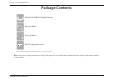
Section 1 - Product Overview Package Contents DIR-842 AC1200 Wi-Fi Gigabit Router Ethernet Cable Power Adapter :L )L &RQ¿JXUDWLRQ 1RWH WI-FI Configuration Note If any of the above items are missing, please contact your reseller. Note: Using a power supply with a different voltage rating than the one included with the DIR-842 will cause damage and void the warranty for this product.
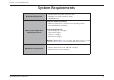
Section 1 - Product Overview System Requirements Network Requirements t "O &UIFSOFU CBTFE DBCMF PS %4- NPEFN t *&&& BD O H C B XJSFMFTT DMJFOUT t &UIFSOFU Computer with the following: t 8JOEPXT¥ .
Section 1 - Product Overview Introduction The D-Link DIR-842 is a IEEE 802.11ac compliant device that delivers up to 3x faster speeds than 802.11n while staying backward compatible with 802.11n/g/b/a devices. Connect the DIR-842 to a cable or DSL modem and provide high-speed Internet access to multiple computers, game consoles, and media players. Create a secure wireless network to share photos, files, music, videos, printers, and network storage. Powered by the 802.
Section 1 - Product Overview Features t 6MUJNBUF (JHBCJU 8JSFMFTT /FUXPSLJOH - The DIR-842 provides up to 300 Mbps wireless connection in 2.4 GHz band, and up to 867 Mbps wireless connection in 5 GHz with other 802.11ac and 802.11n wireless clients. This capability allows users to participate in real-time activities online, such as video streaming, online gaming, and real-time audio. The performance of this 802.11ac wireless router gives you the freedom of wireless networking at speeds 3x faster than 802.
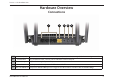
Section 1 - Product Overview Hardware Overview Connections 1 1 -"/ 1PSUT Internet Port 3 Power Receptor 4 Power Button 5 2 3 4 5 $POOFDU &UIFSOFU EFWJDFT TVDI BT DPNQVUFST TXJUDIFT TUPSBHF /"4 EFWJDFT BOE HBNF DPOTPMFT Using an Ethernet cable, connect your broadband modem to this port. Receptor for the supplied power adapter. Press the power button to power the DIR-842 on and off. WPS / Reset Button Short press to start the WPS process.
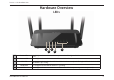
Section 1 - Product Overview Hardware Overview LEDs 1 3 2 1 Power LED Internet LED 3 WPS LED 4 WLAN LED 5 LAN LEDs 1-4 D-Link DIR-842 User Manual 5 4 A solid light indicates that the device is powered on. The light will blink while the device is in recovery mode. A solid light indicates that an Internet link is established. A solid light indicates that the WPS handshake has been completed. The light will blink while the WPS handshake is processing.
Section 2 - Installation Installation This section will walk you through the installation process. Placement of the router is very important. Do not place the router in an enclosed area such as a closet, cabinet, or in the attic or garage.
Section 2 - Installation Wireless Installation Considerations The D-Link wireless router lets you access your network using a wireless connection from virtually anywhere within the operating range of your wireless network. Keep in mind, however, that the number, thickness and location of walls, ceilings, or other objects that the wireless signals must pass through, may limit the range.
Section 2 - Installation Manual Setup 1. Turn off and unplug your cable or DSL broadband modem. This is required. 2. Position your router close to your modem and a computer. Place the router in an open area of your intended work area for better wireless coverage. 6OQMVH UIF &UIFSOFU DBCMF GSPN ZPVS NPEFN PS FYJTUJOH SPVUFS JG VQHSBEJOH UIBU JT DPOOFDUFE UP ZPVS DPNQVUFS Plug it into the LAN port labeled 1 on the back of your router. The router is now connected to your computer.
Section 2 - Installation 4. Plug one end of the included blue Ethernet cable that came with your router into the yellow port labeled INTERNET on the back of the router. Plug the other end of this cable into the Ethernet port on your modem. 4 modem INTERNET 5. Reconnect the power adapter to your cable or DSL broadband modem and wait for two minutes. 6. Connect the supplied power adapter into the power port on the back of the router and then plug it into a power outlet or surge protector.
Section 3 - Configuration Configuration There are several different ways you can configure your router to connect to the Internet and connect to your clients: t % -JOL 4FUVQ 8J[BSE - This wizard will launch when you log into the router for the first time. Refer to page 11. t 234 .PCJMF "QQ - Use your smart device to configure your router. Refer to page”QRS Mobile App” on page 15.
Section 3 - Getting Started Setup Wizard If this is your first time installing the router, open your web browser and enter IUUQ EMJOLSPVUFS MPDBM in the address bar. Alternatively, enter UIF *1 BEESFTT PG UIF SPVUFS EFGBVMU IUUQ Please refer to Configuration on page 19. The wizard is designed to guide you through a step-by-step process to configure your new D-Link router and connect to the Internet. Click Next to continue.
Section 3 - Getting Started If the router does not detect a valid Internet connection, a list of connection types to choose from will be displayed. 4FMFDU ZPVS *OUFSOFU DPOOFDUJPO UZQF UIJT JOGPSNBUJPO DBO CF PCUBJOFE GSPN ZPVS *OUFSOFU TFSWJDF QSPWJEFS BOE DMJDL Next to continue. If the router detected or you selected PPPoE, enter your PPPoE username and password and click Next to continue. Note: If your computer has PPPoE software, make sure to remove it from your computer.
Section 3 - Getting Started For both the 2.4 GHz and 5 GHz segments, create a Wi-Fi network name 44*% VTJOH VQ UP DIBSBDUFST $SFBUF B 8J 'J QBTTXPSE CFUXFFO DIBSBDUFST :PVS XJSFMFTT DMJFOUT will need to have this passphrase or key entered to be able to connect to your wireless network. Click Next to continue. *O PSEFS UP TFDVSF UIF SPVUFS QMFBTF FOUFS B OFX QBTTXPSE :PV XJMM CF prompted for this password every time you want to use the router’s web configuration utility.
Section 3 - Getting Started QRS Mobile App QRS Mobile app allows you to install and configure your router from your mobile device. Note: The screenshots may be different depending on your mobile device’s OS version. Step 1 Search for the free QRS Mobile App on the iTunes Store or Google Play. 4UFQ Once your app is installed, you may now configure your router. Connect to the router wirelessly by going to your wireless utility on your device.
Section 3 - Getting Started Step 4 :PV XJMM TFF UIF XFMDPNF TDSFFO 5BQ Start to proceed, then enter your device password and tap Log In. Tap Next once the Operation Mode screen appears. Step 5 At this point, please ensure that your the router is connected to a modem. Plug one end of the provided Ethernet cable into your DSL or cable modem, and plug the other end into the port marked INTERNET on the DIR-842. Tap Next to automatically detect your Internet connection and proceed to the next step.
Section 3 - Getting Started Step 6 'JSTUMZ FOUFS B OFUXPSL OBNF 44*% PG ZPVS DIPJDF PS MFBWF JU VODIBOHFE to accept the default SSID. Secondly, choose a Wi-Fi password of at least 8 characters. Any device trying to connect to the router wirelessly will need to enter this password the first time it connects. Finally, tap Next to proceed. :PV XJMM CF BTLFE UP FOUFS B 44*% BOE QBTTXPSE GPS ZPVS ()[ OFUXPSL Repeat step 6 and tap Next to proceed. Step 7 Enter the administrator password of your choice.
Section 3 - Getting Started Step 8 :PV XJMM CF QSFTFOUFE XJUI B TVNNBSZ PG ZPVS DIPTFO TFUUJOHT Tap Save to complete the setup and wait for your device to reboot. $POHSBUVMBUJPOT ZPVS EFWJDF IBT CFFO TVDDFTTGVMMZ DPOöHVSFE :PV DBO share this information by tapping Share By E-mail, or tap 'JOJTI to exit the app.
Section 4 - Configuration Configuration To access the configuration utility, open a web-browser such as Internet Explorer and enter IUUQ EMJOLSPVUFS MPDBM Windows and Mac users may also connect by typing the IP address of UIF SPVUFS CZ EFGBVMU UIJT JT IUUQ JO UIF BEESFTT CBS &OUFS ZPVS QBTTXPSE *G ZPV QSFWJPVTMZ GPMMPXFE UIF TFUVQ XJ[BSE TFF 4FUVQ 8J[BSE on page 12, please use the admin password you entered during the wizard. Otherwise, leave the password blank.
Section 4 - Configuration Home 5IF )PNF QBHF EJTQMBZT UIF DVSSFOU TUBUVT PG UIF SPVUFS JO UIF GPSN PG BO JOUFSBDUJWF EJBHSBN :PV DBO DMJDL FBDI JDPO UP EJTQMBZ information about each part of the network at the bottom of the screen. The menu bar at the top of the page will allow you to quickly navigate to other pages. Internet The Home page displays whether or not the router is currently connected to the Internet.
Section 4 - Configuration DIR-842 Click on the %*3 icon to view details about the router and its wireless settings. Here you can see the router’s current wireless settings, as well as its MAC address and IPv4/IPv6 addresses. To reconfigure the network settings, either click (P UP TFUUJOHT on the lower left, or click Settings BU UIF UPQ PG UIF QBHF BOE UIFO Network on the menu that appears. Refer to Network on page 50.
Section 4 - Configuration Connected Clients Click on the Connected Clients icon to view details about the router and its wireless settings. On this page you can see all the clients currently connected to the router, and their IP addresses. To edit each client’s settings, click the pencil icon on the client you want to edit. Name: Enter a custom name for this client. Vendor: Displays the vendor of the device. *1 "EESFTT Enter a specific IP address for this client.
Section 4 - Configuration Settings Wizard In the Settings menu on the bar on the top of the page, click 8J[BSE to open the setup wizard. This is the same wizard that appears when you start the router for the first time. Refer to 4FUVQ 8J[BSE on page 12for details. Internet In the Settings menu on the bar on the top of the page, click Internet to see the Internet configuration options. My Internet Choose your Internet connection type from the drop-down menu.
Section 4 - Configuration Dynamic IP (DCHP) Select Dynamic IP (DHCP) UP PCUBJO *1 BEESFTT JOGPSNBUJPO BVUPNBUJDBMMZ GSPN ZPVS *OUFSOFU 4FSWJDF 1SPWJEFS *41 4FMFDU UIJT PQUJPO JG ZPVS *41 does not give you an IP address to use. Host Name: The host name is optional but may be required by some ISPs. Leave it blank if you are not sure. Primary DNS Enter the primary DNS server IP address assigned by your ISP. This Server: address is usually obtained automatically from your ISP.
Section 4 - Configuration Static IP 4FMFDU 4UBUJD *1 JG ZPVS *1 JOGPSNBUJPO JT QSPWJEFE CZ ZPVS *OUFSOFU TFSWJDF QSPWJEFS *41 *1 "EESFTT Enter the IP address provided by your ISP. Subnet Mask: Enter the subnet mask provided by your ISP. Default Enter the default gateway address provided by your ISP. (BUFXBZ Primary DNS Enter the primary DNS server IP address assigned by your ISP. Server: Secondary DNS Enter the secondary DNS server IP address assigned by your ISP.
Section 4 - Configuration PPPoE Select PPPoE if your Internet connection requires you to enter a username and password. This information is provided by your Internet Service 1SPWJEFS *41 Username: Enter the username provided by your ISP. Password: Enter the password provided by your ISP. Reconnect Select either "MXBZT PO, 0O %FNBOE, or Manual. Mode: Maximum Idle Enter a maximum idle time during which the Internet connection is Time: maintained during inactivity.
Section 4 - Configuration PPTP Choose PPTP 1PJOU UP 1PJOU 5VOOFMJOH 1SPUPDPM JG ZPVS *OUFSOFU 4FSWJDF 1SPWJEFS *41 VTFT B 1151 DPOOFDUJPO :PVS *41 XJMM QSPWJEF ZPV XJUI B username and password. PPTP Server IP Enter the PPTP server IP address provided by your ISP. "EESFTT Username: Enter the username provided by your ISP. Password: Enter the password provided by your ISP. Reconnect Select either "MXBZT PO, 0O %FNBOE, or Manual.
Section 4 - Configuration Secondary DNS Enter the secondary DNS server IP address assigned by your ISP. Server: MTU: Maximum Transmission Unit - you may need to change the MTU for optimal performance with your ISP. Click Save when you are done.
Section 4 - Configuration L2TP Choose - 51 -BZFS 5VOOFMJOH 1SPUPDPM JG ZPVS *OUFSOFU 4FSWJDF 1SPWJEFS *41 VTFT B - 51 DPOOFDUJPO :PVS *41 XJMM QSPWJEF ZPV XJUI B VTFSOBNF and password. - 51 4FSWFS *1 Enter the L2TP server IP address provided by your ISP. "EESFTT Username: Enter the username provided by your ISP. Password: Enter the password provided by your ISP. Reconnect Select either "MXBZT PO, 0O %FNBOE, or Manual.
Section 4 - Configuration Secondary DNS Enter the secondary DNS server IP address assigned by your ISP. Server: MTU: Maximum Transmission Unit - you may need to change the MTU for optimal performance with your ISP. Click Save when you are done.
Section 4 - Configuration DS-Lite DS-Lite is an IPv6 connection type. After selecting DS-Lite, the following parameters will be available for configuration: DS-Lite Select DS-Lite DHCPv6 to let the router allocate the AFTR IPv6 Configuration: address automatically. Select Manual Configuration to enter the AFTR IPv6 address manually. "'53 *1W If you selected Manual Configuration above, enter the AFTR IPv6 "EESFTT address here. B4 IPv6 Enter the B4 IPv4 address value here.
Section 4 - Configuration IPv6 To configure an IPv6 connection, click the IPv6 link. To return to the IPv4 settings, click IPv4. My Internet $IPPTF ZPVS *1W DPOOFDUJPO UZQF GSPN UIF ESPQ EPXO NFOV :PV Connection Is: will be presented with the appropriate options for your connection type. $MJDL "EWBODFE 4FUUJOHT . to expand the list and see all of the options. For "VUP %FUFDUJPO refer to "VUP %FUFDUJPO on page 33. For Static IPv6 refer to Static IPv6 on page 35.
Section 4 - Configuration Auto Detection "VUP %FUFDUJPO NPEF OPU "VUP $POöHVSBUJPO NPEF BVUPNBUJDBMMZ EFUFDUT *1W UIF DPOOFDUJPO NFUIPE VTFE CZ ZPVS *OUFSOFU 4FSWJDF 1SPWJEFS *41 *G ZPVS *41 QSPWJEFT BO *1W TFSWJDF BOE "VUP %FUFDUJPO GBJMFE UP EFUFDU JU UIF VTFS NVTU NBOVBMMZ TFMFDU BOPUIFS *1W DPOOFDUJPO UZQF TVDI BT 111P& "VUP $POöHVSBUJPO SE %4 -JUF FUD DNS Type: Select either Obtain DNS server address automatically or Use the following DNS address.
Section 4 - Configuration Autoconfiguration 4FMFDU 4UBUFGVM %)$1W 4-""$ 3%/44 PS 4-""$ 4UBUFMFTT Type: DHCPv6. Router &OUFS UIF *1W BEESFTT MJGFUJNF JO NJOVUFT Advertisement Lifetime: Click Save when you are done.
Section 4 - Configuration Static IPv6 Select Static IP JG ZPVS *1W JOGPSNBUJPO JT QSPWJEFE CZ ZPVS *OUFSOFU TFSWJDF QSPWJEFS *41 BOE UIFZ SFRVFTU UIBU ZPV VTF B TUBUJD *1 Use Link-Local Enable or disable a link-local address. Address: IPv6 Address: If you disabled Use Link-Local Address, enter the address supplied by your ISP. Subnet Prefix If you disabled Use Link-Local Address, enter the subnet prefix length Length: supplied by your ISP. Default Enter the default gateway for your IPv6 connection.
Section 4 - Configuration Autoconfiguration 4FMFDU 4UBUFGVM %)$1W 4-""$ 3%/44 PS 4-""$ 4UBUFMFTT Type: DHCPv6. Router &OUFS UIF *1W BEESFTT MJGFUJNF JO NJOVUFT Advertisement Lifetime: Click Save when you are done.
Section 4 - Configuration Auto Configuration (SLAAC/DHCPv6) This is a connection method where the ISP assigns your IPv6 address when your router requests one from the ISP’s server. Some ISPs require you to make some settings on your side before your router can connect to the IPv6 Internet. DNS Type: Select either Obtain DNS server address automatically or Use the following DNS address. Primary DNS If you selected Use the following DNS address above, enter the Server: primary DNS server address.
Section 4 - Configuration Autoconfiguration 4FMFDU 4UBUFGVM %)$1W 4-""$ 3%/44 PS 4-""$ 4UBUFMFTT Type: DHCPv6. Router &OUFS UIF *1W BEESFTT MJGFUJNF JO NJOVUFT Advertisement Lifetime: Click Save when you are done.
Section 4 - Configuration PPPoE Select PPPoE if your Internet connection requires you to enter a username and password. This information is provided by your Internet service QSPWJEFS *41 PPPoE Session: Choose Share with IPv4 to re-use your IPv4 PPPoE username and password, or Create a new session. Username: If you selected Create a new session above, enter the PPPoE username provided by your ISP here.
Section 4 - Configuration Enable DHCP- Enable DHCP-PD for LAN IPv6. PD: LAN IPv6 Link- Displays the router’s LAN link-local address. Local Address: Enable Enable automatic IPv6 address assignment. Automatic IPv6 Address Assignment: Enable Enable or disable DHCP-PD for other IPv6 routers connected to the Automatic LAN interface. DHCP-PD in LAN: Note: This feature requires a smaller subnet prefix than /64 (i.e. allowing for a larger address allocation), such as /63. Contact your ISP for more information.
Section 4 - Configuration IPv6 in IPv4 Tunnel The user can configure the IPv6 connection to run in IPv4 Tunnel mode. IPv6 over IPv4 tunneling encapsulates IPv6 packets in IPv4 packets so that IPv6 packets can be sent over an IPv4 infrastructure. Remote IPv4 Enter the IPv4 remote address you will use. Address: Remote IPv6 Enter the IPv6 remote address you will use. Address: Local IPv4 Enter the IPv4 local address you will use. Address: Local IPv6 Enter the IPv6 local address you will use.
Section 4 - Configuration LAN IPv6 Link- Displays the router’s LAN link-local address. Local Address: Enable Enable or disable the Automatic IPv6 Address Assignment feature. Automatic IPv6 Address Assignment: Enable Enable or disable DHCP-PD for other IPv6 routers connected to the Automatic LAN interface. DHCP-PD in LAN: Note: This feature requires a smaller subnet prefix than /64 (i.e. allowing for a larger address allocation), such as /63. Contact your ISP for more information.
Section 4 - Configuration 6 to 4 In this section the user can configure the IPv6 6 to 4 connection settings. 6to4 is an IPv6 address assignment and automatic tunneling technology that is used to provide unicast IPv6 connectivity between IPv6 sites and hosts across the IPv4 Internet. 6 to 4 Address: Displays the 6 to 4 address. 6 to 4 Relay: Enter the 6 to 4 relay supplied by your ISP. Primary DNS Enter the primary DNS server address. Server: Secondary DNS Enter the secondary DNS server address.
Section 4 - Configuration 6rd In this section the user can configure the IPv6 6rd connection settings. Assign IPv6 Currently unsupported. Prefix: Primary DNS Enter the primary DNS server address. Server: Secondary DNS Enter the secondary DNS server address. Server: Enable Hub and Enable if you want to minimize the number of routes to the Spoke Mode: destination by using a hub and spoke method of networking.
Section 4 - Configuration Enable Check to enable the Automatic IPv6 Address Assignment feature. Automatic IPv6 Address Assignment: Auto Select Stateful (DHCPv6), 4-""$ 3%/44 or 4-""$ 4UBUFMFTT Configuration DHCPv6. Type: Router &OUFS UIF *1W BEESFTT MJGFUJNF JO NJOVUFT Advertisement Lifetime: Click Save when you are done.
Section 4 - Configuration Local Connectivity Only -PDBM $POOFDUJWJUZ 0OMZ allows you to set up an IPv6 connection that will not connect to the Internet. Enable ULA: Click here to enable Unique Local IPv6 Unicast Addresses settings. Use Default Checking this box will automatically configure the ULA prefix for ULA Prefix: the default setting. Current IPv6 This section will display the current settings for your IPv6 ULA.
Section 4 - Configuration Wireless In the Settings menu on the bar on the top of the page, click Wireless to see the wireless configuration options. To configure the router’s guest zone, click the (VFTU Zone link. Refer to (VFTU ;POF on page 11 for details. Click "EWBODFE 4FUUJOHT to expand the list and see all of the options. The following options apply to both the 2.4 GHz and the 5 GHz wireless frequency bands: Status: Enable or disable the wireless frequency band.
Section 4 - Configuration Schedule: Use the drop-down menu to select the time schedule that the Wi-Fi network will be active during. The schedule may be set to "MXBZT Enable, or you can create your own schedules in the Schedules TFDUJPO SFGFS UP Schedule PO QBHFw4DIFEVMFw PO QBHF Click Save when you are done.
Section 4 - Configuration Guest Zone The guest zone feature will allow you to create temporary zones that can be used by guests to access the Internet. These zones will be separate from your main wireless OFUXPSL :PV NBZ DPOöHVSF EJòFSFOU [POFT GPS UIF ()[ BOE ()[ XJSFMFTT CBOET In the Settings menu on the bar on the top of the page, click Wireless, then click the (VFTU ;POF link. Click "EWBODFE 4FUUJOHT to expand the list and see all of the options. The following options apply to both the 2.
Section 4 - Configuration Network This section will allow you to change the local network settings of the router and to configure the DHCP settings. In the Settings menu on the bar on the top of the page, click Network. Click "EWBODFE 4FUUJOHT to expand the list and see all of the options. LAN IP Address: Enter the IP address of the router. The default IP address is .
Section 4 - Configuration DHCP Lease Enter the length of time for the IP address lease in minutes. Time: Always Enable this feature to broadcast your networks DHCP server to LAN/ Broadcast: WLAN clients. WAN Port :PV NBZ TFU UIF QPSU TQFFE PG UIF *OUFSOFU QPSU UP 10 Mbps, Speed: 100 Mbps or "VUP SFDPNNFOEFE UPnP: &OBCMF PS EJTBCMF 6OJWFSTBM 1MVH BOE 1MBZ 61O1 61O1 QSPWJEFT compatibility with networking equipment, software and peripherals.
Section 4 - Configuration Features QoS Engine This section will allow you to prioritize particular clients over others, so that those clients receive higher bandwidth. For example, if one client is streaming a movie and another is downloading a non-urgent file, you might wish to assign the former device a higher priority than the latter so that the movie streaming is not disrupted by the traffic of the other devices on the network. In the Features menu on the bar on the top of the page, click QoS Engine.
Section 4 - Configuration Firewall Settings The router’s firewall protects your network from malicious attacks over the Internet. In the Features menu on the bar on the top of the page, click 'JSFXBMM 4FUUJOHT. Click "EWBODFE 4FUUJOHT to expand the list and see all of the options. Enable DMZ: &OBCMF PS EJTBCMF %FNJMJUBSJ[FE ;POF %.; 5IJT DPNQMFUFMZ FYQPTFT the client to threats over the Internet, and is not recommended in ordinary situations.
Section 4 - Configuration PPTP: Allows multiple machines on the LAN to connect to their corporate network using the PPTP protocol. IPSec (VPN): Allows multiple VPN clients to connect to their corporate network using IPSec. Some VPN clients support traversal of IPSec through /"5 5IJT "QQMJDBUJPO -FWFM (BUFXBZ "-( NBZ JOUFSGFSF XJUI UIF operation of such VPN clients. If you are having trouble connecting with your corporate network, try turning this ALG off.
Section 4 - Configuration IPv4/IPv6 Rules The IPv4/IPv6 Rules section is an advanced option that lets you configure what kind of traffic is allowed to pass through the network. To configure the IPv4 rules, from the Firewall Settings page click IPv4 Rules. To configure IPv6 rules, from the Firewall Settings page click IPv6 Rules. To return to the main Firewall Settings page, click "EWBODFE.
Section 4 - Configuration Port Forwarding Port forwarding allows you to specify a port or range of ports to open for specific devices on the network. This might be necessary for certain applications to connect through the router. In the Features menu on the bar on the top of the page, click 1PSU 'PSXBSEJOH. If you wish to remove a rule, click on its trash can icon in the Delete column. If you wish to edit a rule, click on its pencil icon in the Edit column.
Section 4 - Configuration Virtual Server The virtual server allows you to specify a single public port on your router for redirection to an internal LAN IP Address and Private LAN port. To configure the virtual server, from the Port Forwarding page click Virtual Server. To return to the main Port Forwarding page, click 1PSU 'PSXBSEJOH. If you wish to remove a rule, click on its trash can icon in the Delete column. If you wish to edit a rule, click on its pencil icon in the Edit column.
Section 4 - Configuration Website Filter 5IF XFCTJUF öMUFS TFUUJOHT BMMPX ZPV UP CMPDL BDDFTT UP DFSUBJO XFC TJUFT :PV DBO FJUIFS DSFBUF B MJTU PG TJUFT UP CMPDL PS DSFBUF B MJTU PG TJUFT UP BMMPX XJUI BMM PUIFS TJUFT CFJOH CMPDLFE In the Features menu on the bar on the top of the page, click 8FCTJUF 'JMUFS. If you want to create a list of sites to block, select %&/: DPNQVUFST BDDFTT UP 0/-: these sites from the drop-down menu. All other sites will be accessible.
Section 4 - Configuration Static Routes The Static Routes section allows you to define custom routes to control how data traffic is moved around your network. In the Features menu on the bar on the top of the page, click Static Routes. To configure IPv6 rules, click IPv6 and refer to IPv6 on page 60. To return to the main IPv4 static routes page, click IPv4. If you wish to remove a rule, click on its trash can icon in the Delete column.
Section 4 - Configuration IPv6 To configure IPv6 rules, on the Static Routes page click IPv6. To return to the main IPv4 static routes page, click IPv4. If you wish to remove a rule, click on its trash can icon in the Delete column. If you wish to edit a rule, click on its pencil icon in the Edit column. If you wish to create a new rule, click the "EE 3VMFT button. Click Save when you are done. If you edit or create a rule, the following options will appear: Name: Enter a name for the rule.
Section 4 - Configuration Dynamic DNS .PTU *OUFSOFU 4FSWJDF 1SPWJEFST *41T BTTJHO EZOBNJD DIBOHJOH *1 BEESFTTFT 6TJOH a dynamic DNS service provider, people can enter your domain name in their web browser to connect to your server no matter what your IP address is. In the Features menu on the bar on the top of the page, click Dynamic DNS. Enable Enabling dynamic DNS will reveal further configuration options. Dynamic DNS: Status: Displays the current dynamic DNS connection status.
Section 4 - Configuration IPv6 Host The IPv6 host settings are found at the bottom of the Dynamic DNS page. If you wish to remove a rule, click on its trash can icon in the Delete column. If you wish to edit a rule, click on its pencil icon in the Edit column. If you wish to create a new rule, click the "EE 3FDPSE button. Click Save when you are done. If you edit or create a rule, the following options will appear: Host Name: Enter the host name that you registered with your dynamic DNS service provider.
Section 4 - Configuration Management Time & Schedule Time The Time page allows you to configure, update, and maintain the correct time on the internal system clock. From here you can set the time zone, the Network Time 1SPUPDPM /51 TFSWFS BOE FOBCMF PS EJTBCMF EBZMJHIU TBWJOH UJNF In the Management menu on the bar on the top of the page, click Time & Schedule. Time Zone: Select your time zone from the drop-down menu. Time: Displays the current date and time of the router.
Section 4 - Configuration Schedule Some configuration rules can be set according to a pre-configured schedule. To create, edit, or delete schedules, from the Time page click Schedule. To return to the Time page, click Time. If you wish to remove a rule, click on its trash can icon in the Delete column. If you wish to edit a rule, click on its pencil icon in the Edit column. If you wish to create a new rule, click the "EE 3VMFT button. Click Save when you are done.
Section 4 - Configuration System Log The router keeps a running log of events. This log can be sent to a Syslog server, and sent to your email address. In the Management menu on the bar on the top of the page, click System Log. Enable Logging Check this box to send the router logs to a SysLog Server. If this is to Syslog disabled, there will be no other options on this page. Server: Syslog Server IP Enter the IP address for the Syslog server.
Section 4 - Configuration Admin 5IJT QBHF XJMM BMMPX ZPV UP DIBOHF UIF BENJOJTUSBUPS "ENJO QBTTXPSE BOE FOBCMF remote management. In the Management menu on the bar on the top of the page, click "ENJO. Password: &OUFS B OFX QBTTXPSE GPS UIF BENJOJTUSBUPS BDDPVOU :PV XJMM OFFE UP enter this password whenever you configure the router using a web browser.
Section 4 - Configuration System This page allows you to save the router’s current configuration, load a previously saved configuration, reset the router to its factory default settings, or reboot the router. From the Admin page click System. To return to the Admin page, click "ENJO. Save Settings This option will save the current router configuration settings to a file To Local Hard on your computer. Drive: Load Settings This option will load previously saved router configuration file.
Section 4 - Configuration Upgrade This page will allow you to upgrade the router’s firmware or language pack, either automatically or manually. To manually upgrade the firmware or language pack, you must first download the relevant file from IUUQ TVQQPSU EMJOL DPN. In the Management menu on the bar on the top of the page, click Upgrade. Firmware The current firmware’s version and date will be displayed.
Section 4 - Configuration Statistics On the Statistics page you can view the amount of packets that pass through the router on the WAN, LAN, and wireless segments. In the Management menu on the bar on the top of the page, click Statistics. :PV DBO WJFX UIF Internet, -"/, 8J 'J ()[, or 8J 'J ()[ by clicking on the respective tabs at the top. The graph will update in real time. To clear the information on the graph, click Clear. The traffic counter will reset if the device is rebooted.
Section 4 - Connecting to a Wireless Network Connect a Wireless Client to your Router WPS Button 5IF FBTJFTU BOE NPTU TFDVSF XBZ UP DPOOFDU ZPVS XJSFMFTT EFWJDFT UP UIF SPVUFS JT 814 8J 'J 1SPUFDUFE 4FUVQ .
Section 4 - Connecting to a Wireless Network Windows® 8 WPA/WPA2 *U JT SFDPNNFOEFE UP FOBCMF XJSFMFTT TFDVSJUZ 81" 81" PO ZPVS XJSFMFTT SPVUFS PS BDDFTT QPJOU CFGPSF DPOöHVSJOH ZPVS XJSFMFTT BEBQUFS *G ZPV BSF KPJOJOH BO FYJTUJOH OFUXPSL ZPV XJMM OFFE UP LOPX UIF TFDVSJUZ LFZ 8J 'J QBTTXPSE CFJOH VTFE To join an existing network, locate the wireless network icon in the taskbar, next to the time display.
Section 4 - Connecting to a Wireless Network :PV XJMM UIFO CF QSPNQUFE UP FOUFS UIF OFUXPSL TFDVSJUZ LFZ 8J 'J QBTTXPSE GPS UIF XJSFMFTT OFUXPSL &OUFS UIF QBTTXPSE JOUP UIF box and click Next. *G ZPV XJTI UP VTF 8J 'J 1SPUFDUFE 4FUVQ 814 UP DPOOFDU UP UIF router, you can also press the WPS button on your router at the point to enable the WPS function.
Section 4 - Connecting to a Wireless Network Windows® 7 WPA/WPA2 *U JT SFDPNNFOEFE UP FOBCMF XJSFMFTT TFDVSJUZ 81" 81" PO ZPVS XJSFMFTT SPVUFS PS BDDFTT QPJOU CFGPSF DPOöHVSJOH ZPVS wireless adapter. If you are joining an existing network, you will need to know the security key or passphrase being used. $MJDL PO UIF XJSFMFTT JDPO JO ZPVS TZTUFN USBZ MPXFS SJHIU DPSOFS Wireless Icon 2. The utility will display any available wireless networks in your area.
Section 4 - Connecting to a Wireless Network )JHIMJHIU UIF XJSFMFTT DPOOFDUJPO XJUI 8J 'J OBNF 44*% ZPV would like to connect to and click the Connect button. If you get a good signal but cannot access the Internet, check your TCP/IP settings for your wireless adapter. Refer to the Networking Basics section in this manual for more information. 4. The following window appears while your computer tries to connect to the router.
Section 4 - Connecting to a Wireless Network &OUFS UIF TBNF TFDVSJUZ LFZ PS QBTTQISBTF 8J 'J QBTTXPSE UIBU is on your router and click Connect :PV DBO BMTP DPOOFDU CZ pushing the WPS button on the router. It may take 20-30 seconds to connect to the wireless network. If the connection fails, please verify that the security settings are correct. The key or passphrase must be exactly the same as on the wireless router.
Section 4 - Connecting to a Wireless Network WPS The WPS feature of the DIR-842 can be configured using Windows® 7. Carry out the following steps to use Windows® 7 to configure the WPS feature: 1. Click the Start button and select Computer from the Start menu. 2. Click Network on the left side.
Section 4 - Connecting to a Wireless Network 3. Double-click the DIR-842. DIR-842 *OQVU UIF 814 1*/ OVNCFS PO UIF SPVUFS MBCFM JO UIF Setup > Wireless Setup NFOV JO UIF SPVUFS T XFC 6* BOE DMJDL Next.
Section 4 - Connecting to a Wireless Network 5. Type a name to identify the network. 6. To configure advanced settings, click the icon. Click Next to continue.
Section 4 - Connecting to a Wireless Network 7. The following window appears while the router is being configured. Wait for the configuration to complete. 8. The following window informs you that WPS on the router has been setup successfully. Make a note of the security key as you may need to provide this security key if adding an older wireless device to the network in the future. 9. Click Close to complete WPS setup.
Section 4 - Connecting to a Wireless Network Windows Vista® Windows Vista® users may use the built-in wireless utility. If you are using another company’s utility, please refer to the user manual of your wireless adapter for help with connecting to a wireless network. Most utilities will have a “site survey” option similar to the Windows Vista® utility as seen below. If you receive the Wireless Networks Detected bubble, click on the center of the bubble to access the utility.
Section 4 - Connecting to a Wireless Network WPA/WPA2 *U JT SFDPNNFOEFE UP FOBCMF XJSFMFTT TFDVSJUZ 81" 81" PO ZPVS XJSFMFTT SPVUFS PS BDDFTT QPJOU CFGPSF DPOöHVSJOH ZPVS wireless adapter. If you are joining an existing network, you will need to know the security key or passphrase being used. 1. Open the Windows Vista® Wireless Utility by right-clicking on the XJSFMFTT DPNQVUFS JDPO JO ZPVS TZTUFN USBZ MPXFS SJHIU DPSOFS PG TDSFFO 4FMFDU Connect to a network. 2.
Section 4 - Connecting to a Wireless Network &OUFS UIF TBNF TFDVSJUZ LFZ PS QBTTQISBTF 8J 'J QBTTXPSE UIBU is on your router and click Connect. It may take 20-30 seconds to connect to the wireless network. If the connection fails, please verify that the security settings are correct. The key or passphrase must be exactly the same as on the wireless router.
Section 4 - Connecting to a Wireless Network WPS/WCN 2.0 The router supports Wi-Fi protection, referred to as WCN 2.0 in Windows Vista®. The following instructions for setting this up depends on whether you are using Windows Vista® to configure the router or third party software. When you first set up the router, Wi-Fi protection is disabled and unconfigured. To enjoy the benefits of Wi-Fi protection, the router must be both enabled and configured.
Section 4 - Connecting to a Wireless Network Windows® XP 8JOEPXT¥ 91 VTFST NBZ VTF UIF CVJMU JO XJSFMFTT VUJMJUZ ;FSP $POöHVSBUJPO 6UJMJUZ 5IF GPMMPXJOH JOTUSVDUJPOT BSF GPS 4FSWJDF Pack 2 users. If you are using another company’s utility, please refer to the user manual of your wireless adapter for help with connecting to a wireless network. Most utilities will have a “site survey” option similar to the Windows® XP utility as seen below.
Section 4 - Connecting to a Wireless Network WPA/WPA2 It is recommended to enable WPA on your wireless router or access point before configuring your wireless adapter. If you are joining an existing network, you will need to know the WPA key being used. 1. Open the Windows® XP Wireless Utility by right-clicking on the XJSFMFTT DPNQVUFS JDPO JO ZPVS TZTUFN USBZ MPXFS SJHIU DPSOFS PG TDSFFO 4FMFDU 7JFX "WBJMBCMF 8JSFMFTT /FUXPSLT.
Section 4 - Connecting to a Wireless Network 3. The Wireless Network Connection box will appear. Enter the WPA-PSK Wi-Fi password and click Connect. It may take 20-30 seconds to connect to the wireless network. If the connection fails, please verify that the WPA-PSK settings are correct. The Wi-Fi password must be exactly the same as on the wireless router.
Section 5 - Troubleshooting Troubleshooting This chapter provides solutions to problems that can occur during the installation and operation of the DIR-842. Read the following descriptions if you are having problems. The examples below are illustrated in Windows® XP. If you have a different operating system, the screenshots on your computer will look similar to the following examples. 1.
Section 5 - Troubleshooting t $POöHVSF ZPVS *OUFSOFU TFUUJOHT t (P UP Start > Settings > Control Panel. Double-click the *OUFSOFU 0QUJPOT Icon. From the Security tab, click the button to restore the settings to their defaults. t $MJDL UIF Connection tab and set the dial-up option to Never Dial a Connection. Click the LAN Settings button. Make sure nothing is checked. Click 0,. t (P UP UIF "EWBODFE tab and click the button to restore these settings to their defaults. Click 0, three times.
Section 5 - Troubleshooting 3. Why can’t I connect to certain sites or send and receive emails when connecting through my router? If you are having a problem sending or receiving email, or connecting to secure sites such as eBay, banking sites, and Hotmail, XF TVHHFTU MPXFSJOH UIF .56 JO JODSFNFOUT PG UFO &Y FUD To find the proper MTU Size, you’ll have to do a special ping of the destination you’re trying to go to. A destination could be another computer, or a URL.
Section 5 - Troubleshooting :PV TIPVME TUBSU BU BOE XPSL ZPVS XBZ EPXO CZ FBDI UJNF 0ODF ZPV HFU B SFQMZ HP VQ CZ VOUJM ZPV HFU B GSBHNFOUFE packet. Take that value and add 28 to the value to account for the various TCP/IP headers. For example, lets say that 1452 was the QSPQFS WBMVF UIF BDUVBM .56 TJ[F XPVME CF XIJDI JT UIF PQUJNVN GPS UIF OFUXPSL XF SF XPSLJOH XJUI Once you find your MTU, you can now configure your router with the proper MTU size.
Appendix A - Wireless Basics Wireless Basics D-Link wireless products are based on industry standards to provide easy-to-use and compatible high-speed wireless connectivity within your home, business or public access wireless networks. Strictly adhering to the IEEE standard, the D-Link XJSFMFTT GBNJMZ PG QSPEVDUT XJMM BMMPX ZPV UP TFDVSFMZ BDDFTT UIF EBUB ZPV XBOU XIFO BOE XIFSF ZPV XBOU JU :PV XJMM CF BCMF to enjoy the freedom that wireless networking delivers.
Appendix A - Wireless Basics What is Wireless? Wireless or Wi-Fi technology is another way of connecting your computer to the network without using wires. Wi-Fi uses radio frequency to connect wirelessly, so you have the freedom to connect computers anywhere in your home or office network. Why D-Link Wireless? D-Link is the worldwide leader and award winning designer, developer, and manufacturer of networking products. D-Link delivers the performance you need at a price you can afford.
Appendix A - Wireless Basics 8JSFMFTT 1FSTPOBM "SFB /FUXPSL 81"/ Bluetooth is the industry standard wireless technology used for WPAN. Bluetooth devices in WPAN operate in a range up to 30 feet away. Compared to WLAN the speed and wireless operation range are both less than WLAN, but in return it doesn’t use nearly as much power which makes it ideal for personal devices, such as mobile phones, PDAs, headphones, laptops, speakers, and other devices that operate on batteries.
Appendix A - Wireless Basics Where is wireless used? Wireless technology is expanding everywhere not just at home or office. People like the freedom of mobility and it’s becoming so popular that more and more public facilities now provide wireless access to attract people. The wireless connection in public places is usually called “hotspots”.
Appendix A - Wireless Basics Security Don’t let you next-door neighbors or intruders connect to your wireless network. Secure your wireless network by turning on the WPA or WEP security feature on the router. Refer to product manual for detail information on how to set it up. Wireless Modes There are basically two modes of networking: t Infrastructure – All wireless clients will connect to an access point or wireless router.
Appendix B - Networking Basics Networking Basics Check your IP address After you install your new D-Link adapter, by default, the TCP/IP settings should be set to obtain an IP address from a DHCP TFSWFS J F XJSFMFTT SPVUFS BVUPNBUJDBMMZ 5P WFSJGZ ZPVS *1 BEESFTT QMFBTF GPMMPX UIF TUFQT CFMPX Click on Start > Run. In the run box type cmd and click 0, 8JOEPXT¥ 7JTUB¥ VTFST UZQF cmd in the Start Search CPY At the prompt, type ipconfig and press Enter.
Appendix B - Networking Basics Statically Assign an IP address If you are not using a DHCP capable gateway/router, or you need to assign a static IP address, please follow the steps below: Step 1 Windows® 7 Click on Start > Control Panel > Network and Internet > Network and Sharing Center. Windows Vista® - Click on Start > Control Panel > Network and Internet > Network and Sharing Center > Manage Network Connections. Windows® XP Click on Start > Control Panel > Network Connections.
Appendix C - Technical Specifications Technical Specifications Hardware Specifications t LAN Interface: Four 10/100/1000 Mbps Gigabit Ethernet LAN ports t WAN Interface: One 10/100/100 Mbps Gigabit Ethernet WAN port t 8JSFMFTT *OUFSGBDF ()[ *&&& C H O t 8JSFMFTT *OUFSGBDF ()[ *&&& B O BD Operating Voltage t Input: 100~240 V AC, 50~60 Hz t Output: 12 V DC, 1 A Temperature t Operating: 32 ~ 104 o' _ o$ t Non-Operating: -4 ~ 149 o' _ o$ Humidity t Operating: 10%
Appendix D - Regulatory Information Regulatory Information 'FEFSBM $PNNVOJDBUJPO $PNNJTTJPO *OUFSGFSFODF 4UBUFNFOU This equipment has been tested and found to comply with the limits for a Class B digital device, pursuant to Part 15 of the FCC Rules. These limits are designed to provide reasonable protection against harmful interference in a residential installation.
Appendix D - Regulatory Information 5IJT EFWJDF NBZ OPU DBVTF JOUFSGFSFODF BOE 5IJT EFWJDF NVTU BDDFQU BOZ JOUFSGFSFODF JODMVEJOH JOUFSGFSFODF UIBU NBZ DBVTF VOEFTJSFE operation of the device. Cet appareil est conforme aux CNR exemptes de licence d’Industrie Canada.