FCC Notices This device complies with Part 15 of the FCC Rules. Operation is subject to the following two conditions: (1) this device may not cause harmful interference, and (2) this device must accept any interference received, including interference that may cause undesired operation. CAUTION: Change or modification not expressly approved by the party responsible for compliance could void the user’s authority to operate this equipment.
FCC Federal Communication Commission Interference Statement This equipment has been tested and found to comply with the limits for a Class B digital device, pursuant to Part 15 of the FCC Rules. These limits are designed to provide reasonable protection against harmful interference in a residential installation. This equipment generates, uses and can radiate radio frequency energy and, if not installed and used in accordance with the instructions, may cause harmful interference to radio communications.
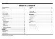
Table of Contents Table of Contents PACKAGE CONTENTS .......................................................................................... 1 SYSTEM REQUIREMENTS ..................................................................................... 1 FEATURES .......................................................................................................... 2 HARDWARE OVERVIEW ........................................................................................ 3 Connections ..................
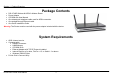
Section 1 - Product Overview • • • • • • Package Contents DSL-2740R Wireless N ADSL2+ Modem Router Power Adapter CD-ROM with User Manual One twisted-pair telephone cable used for ADSL connection One straight-through Ethernet cable One Quick Installation Guide Warning: The Router must be used with the power adapter included with the device.
Section 1 - Product Overview 11 • • • • • • • • • • • • • Features PPP (Point-to-Point Protocol) Security – The Router supports PAP (Password Authentication Protocol) and CHAP (Challenge Handshake Authentication Protocol) for PPP connections. The Router also supports MSCHAP. DHCP Support – Dynamic Host Configuration Protocol automatically and dynamically assigns all LAN IP settings to each host on your network. This eliminates the need to reconfigure every host whenever changes in network topology occur.
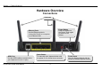
Section 1 - Product Overview Hardware Overview Connections Antennas Ethernet Ports Use the Ethernet ports to connect the Router to a computer or an Ethernet LAN. ADSL Port Use the ADSL cable to connect to the your telephone line (RJ-11 port). D-Link DSL-2740R User Manual Power Button Push in to power-on the Router. Push again to power-off the Router. Reset Button To manually reset, depress button with the power on for at least seven seconds.
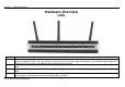
Section 1 - Product Overview Hardware Overview LEDs LED Power LAN WLAN DSL Description A steady green light indicates the unit is powered on. When the device is powered off this remains dark. Lights steady green during power on self-test (POST). Once the connection status has been settled, the light will blink green. If the indicator lights steady red after the POST, the system has failed and the device should be rebooted. A solid green light indicates a valid link on startup.
Section 1 - Product Overview Internet A solid green light indicates the WAN IP address from IPCP or DHCP and DSL is up or a static IP address is configured and PPP negotiation has been successfully completed. If the indicator blinks green, this means the Router is active. If the Router power is off, this remains dark. A solid red light indicates there is no DHCP response, no PPPoE response, PPPoE authentication has failed, and/or there is no IP.
Section 2 – Installation Installation This section will walk you through the installation process. Placement of the Router is very important. Do not place the Router in an enclosed area such as a closet, cabinet, or in the attic or garage. Before You Begin Please read and make sure you understand all the prerequisites for proper installation of your new Router. Have all the necessary information and equipment on hand before beginning the installation.
Section 2 – Installation Web Browser Any common Web browser can be used to configure the Router using the Web configuration management software. The program is designed to work best with more recently released browsers such as Opera, Microsoft Internet Explorer® version 6.0, Netscape Navigator® version 6.2.3, or later versions. The Web browser must have JavaScript enabled. JavaScript is enabled by default on many browsers.
Section 2 – Installation Information you will need from your ADSL service provider Username This is the Username used to log on to your ADSL service provider’s network. Your ADSL service provider uses this to identify your account. Password This is the Password used, in conjunction with the Username above, to log on to your ADSL service provider’s network. This is used to verify the identity of your account.
Section 2 – Installation VPI Most users will not be required to change this setting. The Virtual Path Identifier (VPI) is used in conjunction with the Virtual Channel Identifier (VCI) to identify the data path between your ADSL service provider’s network and your computer. If you are setting up the Router for multiple virtual connections, you will need to configure the VPI and VCI as instructed by your ADSL service provider for the additional connections.
Section 2 – Installation Information you will need about your LAN or computer : Ethernet NIC If your computer has an Ethernet NIC, you can connect the DSL-2740R to this Ethernet port using an Ethernet cable. You can also use the Ethernet ports on the DSL-2740R to connect to other computer or Ethernet devices. DHCP Client status Your Router is configured, by default, to be a DHCP server. This means that it can assign an IP address, subnet mask, and a default gateway address to computers on your LAN.
Section 2 – Installation Power on Router The Router must be used with the power adapter included with the device. 1. Insert the AC Power Adapter cord into the power receptacle located on the rear panel of the Router and plug the adapter into a suitable nearby power source. 2. Depress the Power button into the on position. You should see the Power LED indicator light up and remain lit. The Status LED should light solid green and begin to blink after a few seconds. 3.
Section 2 – Installation Network Connections Connect ADSL Line Use the ADSL cable included with the Router to connect it to a telephone wall socket or receptacle. Plug one end of the cable into the ADSL port (RJ-11 receptacle) on the rear panel of the Router and insert the other end into the RJ-11 wall socket. If you are using a low pass filter device, follow the instructions included with the device or given to you by your service provider.
Section 3 – Configuration Setup This section will show you how to set up and configure your new D-Link Router using the Web-based configuration utility. Web-based Configuration Utility Connect to the Router To configure the WAN connection used by the Router it is first necessary to communicate with the Router through its management interface, which is HTML-based and can be accessed using a web browser.
Section 3 – Configuration Quick Setup This chapter is concerned with using your computer to configure the WAN connection. The following chapter describes the various windows used to configure and monitor the Router including how to change IP settings and DHCP server setup. QUICK SETUP Click the Setup Wizard link in the middle of the top of the window of the Router’s opening page to launch a series of setup windows.
Section 3 – Configuration QUICK SETUP – OPENING WINDOW The first window of the Setup Wizard lists the basic steps in the process. These steps are as follows: 1. Change the Router password. 2. Configure the connection to the Internet. 3. Save the new configuration settings and reboot the system. QUICK SETUP – CHANGE YOUR ROUTER PASSWORD This window of the Setup Wizard is used to change the Router password.
Section 3 – Configuration QUICK SETUP – SELECT THE INTERNET CONNECTION TYPE Now use the drop-down menus to select the Country, ISP Provider, and Connection Type used for the Internet connection, and enter VPI and VCI values if applicable. Your ISP has given this information to you—any information that is not required for your provider will automatically be grayed out in this window and subsequent Quick Setup windows.
Section 3 – Configuration QUICK SETUP – PPPOE/PPPOA CONFIGURATION Type in the User Name and Password used to identify and verify your account to the ISP. If you are instructed to change the VPI or VCI number, type in the correct setting in the available entry fields. Most users will not need to change these settings. The Internet connection cannot function if these values are incorrect. Some users may have to adjust the Connection Type from the drop-down menu at the bottom of this Setup Wizard window.
Section 3 – Configuration QUICK SETUP – DYNAMIC IP CONFIGURATION If you are instructed to change the VPI or VCI numbers, type in the correct setting in the available entry fields. The Internet connection cannot function if these values are incorrect. Select the specific Connection Type from the drop-down menu. The available connection and encapsulation types are 1483 Bridged IPLLC and 1483 Bridged IP VC-Mux. You may want to copy the MAC address of your Ethernet adapter to the Router.
Section 3 – Configuration QUICK SETUP – STATIC IP CONFIGURATION Enter values for VPI, VCI, IP Address, Subnet Mask, Default Gateway IP address, Preferred DNS Server IP address, and Alternate DNS Server IP address as instructed by your ISP. The Internet connection cannot function if these values are incorrect. Select the specific Connection Type from the drop-down menu.
Section 3 – Configuration QUICK SETUP – FINISH Finally you can confirm that the setup process is completed. If you are satisfied that you have entered all the necessary information correctly, click the Finish button to save the new configuration. If you need to change settings from a previous window, click the Back button.
Section 3 – Configuration ADSL Setup To access the ADSL Setup window, simply login to the Router or click either ADSL Setup in the Setup directory or Setup on the tool bar at the top of the Web manager window. The Manual Setup check box is selected by default.
Section 3 – Configuration PPPoE/PPPoA To configure a PPPoE or PPPoA type WAN connection, follow these steps: 1. Type the Username and Password used for your ADSL account. A typical User Name will be in the form “user1234@isp.co.uk.” The Password may be assigned to you by your ISP or you may have selected it when you set up the account with your ISP. The Service Name field is used for the name of your Internet Service Provider. This is optional. 2. Choose the Connection Type from the drop-down menu.
Section 3 – Configuration Dynamic IP Address A Dynamic IP Address connection configures the Router to automatically obtain its global IP address from a DHCP server on the ISP’s network. The service provider assigns a global IP address from a pool of addresses available to the service provider. Typically the IP address assigned has a long lease time, so it will likely be the same address each time the Router requests an IP address. To configure a Dynamic IP Address WAN connection, follow these steps: 1.
Section 3 – Configuration Static IP Address When the Router is configured to use Static IP Address assignment for the WAN connection, you must manually assign a global IP Address, Subnet Mask, and Default Gateway IP address used for the WAN connection. To configure a Static IP Address WAN connection, follow these steps: 1. Change the IP Address, Subnet Mask, and Default Gateway as instructed by your ISP. These are the global IP settings for the WAN interface.
Section 3 – Configuration Bridge Mode For Bridged connections it will be necessary for most users to install additional software on any computer that will use the Router for Internet access. The additional software is used for the purpose of identifying and verifying your account, and then granting Internet access to the computer requesting the connection. The connection software requires the user to enter the User Name and Password for the ISP account.
Section 3 – Configuration Wireless Setup To access the Wireless Setup window, click the Wireless Setup button in the Setup directory. The two essential settings for wireless LAN operation are the Wireless Network Name (SSID) and Wireless Channel. The SSID (Service Set Identifier) is used to identify a group of wireless LAN components. The SSID can be visible (broadcast) or hidden (not broadcast). Follow the instructions below to change wireless network settings. 1. The Wireless LAN is enabled by default.
Section 3 – Configuration WEP WEP (Wireless Encryption Protocol or Wired Equivalent Privacy) encryption can be enabled for security and privacy. WEP encrypts the data portion of each frame transmitted from the wireless adapter using one of the predefined keys. Decryption of the data contained in each packet can only be done if the both the receiver and transmitter have the correct key. By default, authentication is disabled on the access point. To enable WEP, select WEP in the Security Mode drop-down list.
Section 3 – Configuration WPA-Personal WPA uses an encryption method combined with an authentication procedure that requires an acceptance of a pre-configured password. WPA or Wireless Protection Access is an improved standard of wireless security. The T-KD 318 also supports two common encryption types TKIP and AES (explained below). To configure WPA settings, select WPA-Personal in the Security Mode drop-down list.
Section 3 – Configuration LAN Setup To access the LAN Setup window, click the LAN Setup button in the Setup directory. You can configure the LAN IP address to suit your preference. Many users will find it convenient to use the default settings together with DHCP service to manage the IP settings for their private network. The IP address of the Router is the base address used for DHCP.
Section 3 – Configuration You may also configure DNS settings when using the Router in DHCP mode (Advanced > DNS Setup). When “Obtain DNS server address automatically“ is clicked under DNS Server Configuration on the DNS Setup window, the Router will automatically relay DNS settings to properly configured DHCP clients. To manually enter DNS IP addresses, click the “Use the following DNS server addresses“ radio button and type in a Preferred DNS Server and Alternate DNS Server in the fields provided.
Section 3 – Configuration Time and Date To access the Time and Date window, click the Time and Date button in the Setup directory. The Router provides a number of options to maintain current date and time including NTP. To configure system time on the Router, select the method used to maintain time.