DVX-7090 VoIP Router User's Guide © 2006 D-Link Computer Corp.
D-Link Voice System DVX-7090 VoIP Router for organizations Document №: 1 Document type: User's Guide Document status: Version 1.2.0.0 Date of issue: 10.10.2006 TRADEMARKS T rad emarks us ed in th is te xt: D-L ink and the D -L IN K lo go a re trad emarks o f DL ink C ompu ter Cor por ation ; Micr oso ft an d W ind ows ar e reg is te re d tra demarks o f Micr oso ft Co rpor a tion .
Contents 1 INTRODUCTION ......................................................................................................................................5 1.1 1.2 1.3 1.4 2 DOCUMENT PROFILE ..............................................................................................................................5 AUDIENCE..............................................................................................................................................5 TYPOGRAPHICAL CONVENTIONS ........
Contents 6 USER INTERFACE .................................................................................................................................72 6.1 6.2 6.3 7 CONFIGURING USER’S DATA ................................................................................................................72 VIEWING STATISTICS ...........................................................................................................................74 MANAGING VOICE PROMPTS ..............................
Introduction 1 INTRODUCTION 1.1 DOCUMENT PROFILE This manual describes the D-Link DVX-7090 VoIP Router and explains how to configure and operate it. 1.2 AUDIENCE This document is intended for computer systems specialists tasked with deployment and configuration of the DVX-7090 VoIP Router. The readers of this document are assumed to be familiar with the concepts of IP telephony and principles of networking.
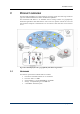
Product overview 2 PRODUCT OVERVIEW The DVX-7090 VoIP Router is a packet telephony switching system with a full range of features typical for traditional PBXs and a number of additional capabilities. The DVX-7090 VoIP Router is an affordable branch exchange solution for geographically distributed organizations that eliminates the need to have two separate networks for voice and data and allows telephone communications over the same line that subscribers use for Internet access. Fig.
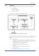
Product overview 2.2 SOFTWARE The DVX-7090 software has a modular structure that includes five functional components: Control Unit (CU), Switching Unit (SU), Database server (DBS) and Web-interface (WI). Fig. 2 presents a block diagram of the D-Link VoIP Router software Fig.
Product overview The DBS is a suite of XML files. The DBS is a repository of data used to store and provide access to user records, the routing table, information about gateways and the system configuration. 2.3 ROUTER FEATURES The DVX-7090 VoIP Router allows: 2.4 Call holds Call transfer Conditional and unconditional call forwarding Conference calls (max.
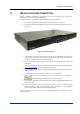
Installation and connection 3 INSTALLATION AND CONNECTION Prepare a Windows workstation connected to the local area network. You will need the workstation to access the newly installed Router. To install and power on your DVX-7090 VoIP Router, proceed as follows: 1. Unpack the supplied Router and install the box at a location of your choice 2. Connect the DVX-7090 VoIP Router to the LAN switch through the Ethernet port (port 2 in Fig. 3) Fig. 3 DVX-7090 front panel 3.
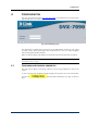
Configuration 4 CONFIGURATION Start your web browser and enter http://192.168.224.226 on the address line to access the logon page of the Router’s web interface. Fig. 4 DVX-7090 logon page The initial logon credentials that provide access to the administration interface of your system are admin, qwerty. If the entered login name and password are correct, you will be displayed with the main page of the Web interface.
Configuration Fig.
Configuration Fig.
Configuration Fig. 7 SMTP server settings box Note: It is assumed that the configured SMTP Server does not require authorization. The date-time dialog box allows you to set the current date and time. Fig. 8 Date and time setting box Use NTP. Select the checkbox Use NTP if you wish to use automatic time synchronization and configure NTP time servers. Deselect the checkbox when you plan to make manual date-time setting.
Configuration When setting the date and time manually, enter the current date and time in the respective boxes and click . Click remove an erroneous entry. whenever you want to update the date-time setting or The purpose of the dialog Change password is self-explanatory. A change of the access credentials set by the manufacturer (admin, qwerty) should be the first procedure you perform on your newly deployed system. Fig. 9 Change password dialog The configuration boxes SIP registrar and H.
Configuration Fig. 11 Table of configured user extensions You can change the quantity of records displayed simultaneously by entering the desired number of records in the text box Show users per page above the table and clicking . You can skip directly to any portion of the records or page through the displayed listing successively by clicking the page numbers on the blue bar under the table.
Configuration - Registered – the endpoint is successfully registered with the system; - Unregistered – the endpoint is unregistered; - In-call – the endpoint has established a connection with a remote party; - Failed – unsuccessful endpoint registration. - empty field - no successful endpoint registration has occurred includes two buttons – and . is the button that you click to make a duplicate of the record is the delete button used to remove the record.
Configuration Fig. 13 User configuration form The configuration form comprises five types of configuration parameters: Basic settings (User name, Phone number, Signaling, IP address, IP Port ,E-mail Pincode, and Web password) Registration settings (Login, Password, Web password) General options (NAT, Fax T.38, Convert etc.) SIP options (Ringback Tone, Allow SIP Redirect, Allow noproxy) H.323 options (Tunneling, Fast Start, Multiple Fast Start, Ext, T.38 compatibility, Start H.
Configuration Note: You may skip entering an IP address and port if the checkbox Registration is selected, meaning that the endpoint being configured is a registering entity 6. Type the user’s email address in the E-mail edit field as the destination for voice messages delivered by the DVX-7090 Router Voice-to-email mechanism. 7. Enter the user’s PIN-code in the edit field Pin code to grant the user access to the Impersonate functionality. 8.
Configuration Fig. 16 NAT- , fax-related and protocol-specific settings The combo box NAT serves to select a NAT traversal policy and offers triple choice: direct means that call packets will go direct without enabling NAT traversal forced stands for the NAT traversal function enabled detect denotes automatic detection of NAT presence - Select direct when you are positive that communication with the endpoint you are configuring does not involve network address translation (NAT).
Configuration DTMF Options the DTMF Options combo box is used to select a type of DTMF digits payload. The available options include: 1. RFC2833 for all terminal equipment types 2. INFO V.1 for CISCO SIP terminals 3. INFO V.2 for Nortel SIP terminals Dealing with H.323 Options: Tunneling enables/disables encapsulation of H.245 messages Fast Start enables/disables FastStart Multiple FastStart. With Multiple FastStart set to ‘true’ the system includes FastStart in every packet Ext T.
Configuration 1. Click 2. Select a condition (Busy, No answer, Unreachable, Unconditional) that will cause call forward using the combo box in the column Fwd Condition 3. If the forward rule being configured applies to a particular calling number only, type the necessary calling number in the edit box Source. Alternatively, you can write a regular expression that covers a series of numbers. Leave the edit box intact if the calling number is of no importance for the call forward you are configuring.
Configuration Fig. 18 Codeсs options Enter a number of frames per packet in the neighboring edit box FPP with due regard to the endpoint capability and buffer size. Information about codec frame sizes is given in the table below. Table 2 Frame sizes by codecs Codec Frame size G.729 10 ms G.729A 10 ms G.723 30 ms G.711-aLaw 1 ms G.711-uLaw 1 ms GSM 06.01 20 ms Therefore, if an endpoint can accept no more than, say, 60ms worth of audio per packet, for G.711 you can enter the value 60; for G.
Configuration 4.2.6 DEFAULT USER The Default user account is the only preconfigured user account that exists in the system at the time of the first startup. Fig. 19 Users table on first start The existence of the Default user record is a must therefore you cannot delete this record. The system uses the Default user account whenever a call comes originated by a user not registered with the system. 4.3 CONFIGURING GATEWAYS To access the page Gateways, press gateways as shown in Fig. 20 .
Configuration shows the name the gateway is assigned in the system includes , the button that invokes the groups dialog shows the gateway’s current registration status. Possible values include: - Registered – the gateway is successfully registered with the DVX-7090 Router - In Call – the gateway is handling calls - External – the DVX-7090 Router is registered to the gateway - Both – combination of Registered and External incorporates the button that you click to delete the record.
Configuration 4.3.1 - Parameters for DVX-7090 Router registrations with external registrars (Login, Password, Port, TTL, Security type, Endpoint type) - NAT-, fax-related and signaling-dependent settings - Codec capability settings BASIC GATEWAY SETTINGS Basic gateway settings include the following configuration parameters: Fig. 22 Basic gateway attributes Note: The name entered in the field Gateway name is used as the gateway’s identifier in registrations to a remote gatekeeper/SIP registrar.
Configuration Fig. 23 Gateway registration panel This category of settings is used to configure the registration parameters of the gateway that include: 4.3.3 - the checkbox Registration. A selected checkbox means that the gateway being configured will register to the DVX-7090 Router. - Login is a text box for the gateway’s registration name - Password is an edit field for password entries. - TTL is a box for registration time-to-live data. D-LINK DVX-7090 ROUTER REGISTRATION SETTINGS Fig.
Configuration - TTL provides an edit box for entering a time-to-live registration period in seconds - Security type is a combo box with types of logon credentials encryption: - 4.3.
Configuration Fig. 26 Table of services The intent of the table columns is as follows: contains the checkbox Enabled that shows if the service is available in the system. contains the edit button . Click this button to change the voice prompt or prompts associated with the service. shows a descriptive name of the service presents the command associated with the service contains the delete button To add a new service, click DVX-7090 VoIP Router .
Configuration Fig. 27 New service dialog The displayed new-service configuration form is shown in Fig. 27. Note: The way the invoked new-service configuration form looks depends on what service you are configuring. The Prompts configuration dialog is displayed only when DISA and Impersonate commands are selected in the combo box Command. The dialog Forward options appears only when configuring DISA and Group call services. 1. Select the checkbox Enabled to make the newly created record active 2.
Configuration Whenever necessary click to refresh the view. Click to remove unneeded records only. Whenever it is required to disable a service record for some time, deselect the checkbox Enabled to save the trouble of configuring the service anew. 4.4.1 COMMANDS THAT INVOKE SERVICES The items that populate the drop-down list of the combo box Command are actually command options that cause execution of a certain algorithm.
Configuration 4.5 CONFIGURING THE ROUTING TABLE Preparation of the routing table essentially means creation of call handling rules. Click the tab to access the configuration page illustrated in Fig. 28 Fig. 28 Routing table The columns of the routing table have the following meaning: contains a checkbox. A selected checkbox identifies a call handling rule currently in effect. A deselected checkbox disallows the DVX-7090 Router to apply the rule. contains , the Edit button.
Configuration - Service shows the name of the invoked service (when the command is Service ) or the name of the target gateway (when the command is Dial gateway). includes the button that invokes the groups dialog. To include the rule you are configuring into a group, select the necessary checkbox in the displayed groups dialog box and click . Note: The configured rule will apply only if the call originator and the rule belong to the same access group.
Configuration Service 4.5.2 Service name Provides the specified service WHY POSITION OF ROUTING RULES IN THE TABLE IS IMPORTANT The Router picks rules in the routing table one by one starting from the topmost.
Configuration 4.6 GROUPS AND GROUPING 4.6.1 GENERAL In the DVX-7090 Router you can do grouping based on access to the Router’s features and an organizational principle. Grouping allows you to economize on the configuration effort, and is a prerequisite to some of the Router functions and services (for example, pick up and group calls.) You need to specify groups when you configure users, services and routes. Users.
Configuration - pick up. Groups of the type ‘pickup’ include members with the capability to perform call pick up and group call recipients. contains a checkbox selection/deselection of which allows/disallows access to the call transfer service. contains a checkbox selection/deselection of which allows/disallows access to the call forwarding service contains a checkbox selection/deselection of which allows/disallows access to the conferencing service.
Configuration 4.7 MANAGING VOICE PROMPTS Voice prompts management consists in an authorized person (system administrator or user) replacing the default prompts with customized ones. Prompt management rights of users vary with the type of the user account in the system. The system administrator has access to all prompts and can replace default prompts with customized ones. After replacement the prompts newly added by the administrator become default.
Configuration Fig. 33 Prompt upload dialog to open the file dialog, find the .wav file with the necessary prompt and Click click . The prompt file must be a valid .wav file with voice encoded using the PCM codec (PCM – 16 bits mono, 8 KHz). PCM encoding can be done with the help of the standard Microsoft recorder utility that comes with the operating system. Note: The uploaded custom prompt overwrites the current sound file and becomes the default prompt in the system.
Configuration 4.8 CDRS AND LOGS 4.8.1 CALL DETAIL RECORDS (CDRS) The DVX-7090 Router writes information about calls to files comprised of CDRs (Call Detail Records). The system generates two types of CDRs: 4.8.2 • User CDRs that contain information about calls involving the user extension. A user CDR provides data about the call originator and destination, date and time of the call session start and end, call disconnect reason etc. Each new call entails creation of a new record with call details.
Configuration shows the date and time of the call. presents the caller’s number displays the number of the called party provides information about the in-call time in the hh:mm:ss notation shows the disconnect reason for the call. The disconnect reason is output as a verbal interpretation of a Q931 disconnect cause code or SIP disconnect response where no applicable Q931 code is found. The underlined column name is an indication that you can click the name to sort the table records accordingly.
Configuration Fig. 35 User CDRs User CDRs are call detail records that include information about the date and time of the call, call direction (incoming or outgoing), the other call party’s name and number, and the call’s disconnect reason. You can view downloaded CDR data in Microsoft Excel. To view a downloaded CDR file in Microsoft Excel: 1. Start Excel 2. Click File –> Open 3. Find the downloaded CDR file you wish to inspect 4.
Configuration 7. The text-import wizard will display the next dialog where you may wish to specify the type of data column-wise. It is advisable to leave the type of data General as it appears in all the columns of the table, though. 8. Click Finish to complete the data import procedure. The result of the import is shown in Fig.
Configuration Fig. 36 CDR file data imported to Excel Note: The function for calculating the duration of a call session is =(Cn-Bn)/10,000,000 (seconds), where n denotes the number of a row of cells. For example, the duration of the call session shown in the first row of the table in Fig. 36 is (C1-B1)/10,000,000 = 19 sec. 4.8.3 LOGS In addition to CDR files the DVX-7090 Router writes log files designed to keep track of the system operation and events..
Configuration When addressing the customer support service, attach the pertinent four log files to the bug report. Note: CDR and log files take up quite a large amount of disk space. So, at the expiry of a certain period of time the system archives the logs and saves the archive to the Router flash drive. Click to access the Logs page (see Fig. 37): Fig. 37 Logs page The Logs page consists of two parts: the CDRs and logs management form and the table of log files.
Configuration – the column for log file names. contains two buttons and . Use workstation, use to delete the selected file. Note: Deletion of the currently open log file is impossible. The button refreshes the table view. button deletes all files from the table. The 4.8.4 to download the selected file to your VIEWING LOGS Log files are necessary for debugging purposes. In case of a addressing to the customer support service you can attach a log file to the bug report.
Configuration How-to’s 4.
Configuration How-to’s Click to bring up the upload dialog (see Fig. 40). Fig. 40 Version upload dialog box Click to display the file dialog and find the SW update on the host you are using to access the Router. Click to upload the update to the Router host server. If there is not enough free disk space, an error message appears above the table of versions: Delete one of the earlier versions to be able to add a new one.
Configuration How-to’s When the newly uploaded version appears in the table of versions, chose a version selected to be operational at the moment and click for the made changes to take effect. allows you to make backups of the current The button configuration database and save them to your computer. button allows you to upload the saved version of the The configuration database to the Router host. button allows you to cancel all the application settings and revert to The the ‘ex-works’ configuration.
Configuration How-to’s 6. The OS image selected, click Router host. to upload the image to the DVX-7090 The uploaded OS installs automatically and becomes current. The newly installed and current OS version is displayed on the bottom line of the table ‘Operating system updates’ allows you to roll back to the previous version of the OS. It is The button strongly recommended that you use this button only when it is absolutely necessary.
Configuration How-to’s 5 CONFIGURATION HOW-TO'S 5.1 HOW TO CONFIGURE ROUTING PATH TO VOICE TO EMAIL When started, the Voice-to-email service prompts the caller to leave a message after the tone, records the caller’s message, converts it into a .wav sound file and sends the file to the user’s email address. To configure a routing path to the Voice-to-email service: to access the routing table page. 1. Click 2. Click 3. Replace the default name Route #...
Configuration How-to’s 8. Click to add the newly configured record to the table of configured routes. This done, you will return to the Routes page again. This step completes the Voice-to-eMail route configuration procedure.
Configuration How-to’s 5.2 HOW TO CONFIGURE ROUTING PATH TO DIRECT INWARD SYSTEM ACCESS To enable an authorized user to access all or some of the D-Link DVX-7090 Router services from a remote location, create the DISA service with the required range of accessible features. Suppose your objective is to create two routes to two different DISA services – the main one with unlimited access to all of the DVX-7090 Router features and customized DISA with access to conference calls only.
Configuration How-to’s 8. Click 9. Click to confirm your choice to add another record 10. Give the new DISA service some other name (say, DISA limited) 11. Repeat steps 4 through 6 of the configuration sequence. 12. Click in the column Conferences only. and in the pop-up menu select the checkbox to confirm your choice 13. Click 14. Click to access the routing table page 15. Click to bring up the add-new-route dialog 16.
Configuration How-to’s DVX-7090 VoIP Router 2. Replace the default route name DISA main clone with the name you have chosen for the limited DISA (DISA_conferences, for example) 3. Select the option DISA limited in the combo box Argument 4. Replace the destination number 799 with the destination number 798 in the Match entry box on the line Destination 5. Click to add the newly configured record to the table of configured routes. This done, you will return to the Routes page again.
Configuration How-to’s 5.3 HOW TO CONFIGURE ROUTING PATH TO EXTENSION NUMBERS To configure call routing to DVX-7090 Router extensions: to access the routing table page. 1. Click 2. Click 3. In the text box Route name of the add-new-route dialog replace the default name Route #... entering some descriptive name, for example Route to local users. 4. Make sure the checkbox Enabled is selected or the routing rule will remain inactive 5. Select the option Dial User in the combo box Command 6.
Configuration How-to’s 5.4 HOW TO CONFIGURE ROUTING PATH FOR OUTBOUND CALLS To create a rule for calls leaving the system do the following: 1. Click to access the routing table page. 2. Click to add a call handling rule. 3. In the text box Route name of the add-new-route dialog replace the default name Route #... entering a descriptive name to your liking, for example Outgoing calls. 4. Select the option Dial Gateway in the combo box Command 5.
Configuration How-to’s 5.5 HOW TO CONFIGURE ROUTING PATH TO CALL PICKUP The DVX-7090 Router provides for two types of call pickup: 1. group call pickup and 2. directed call pickup Group call pickup allows you to answer any ringing phone that is in the same pickup group with you simply by dialing the pickup number. In directed call pickup you must enter the call pickup key sequence and dial the extension number of the ringing phone to answer the call.
Configuration How-to’s Note: To make call pick up possible the owner of the ringing phone and the configured rule must belong to the same access group. 10. Click DVX-7090 VoIP Router to confirm your choice.
Configuration How-to’s 5.6 HOW TO CONFIGURE ROUTING PATH TO IMPERSONATE FUNCTION The Impersonate function allows a caller who enters a specific PIN code to access the Router‘s services and features configured for the account of the user to which the entered PIN code belongs. Suppose, the administrator assigns the Impersonate function key sequence 777.
Configuration How-to’s DVX-7090 VoIP Router page 59 of 83
Configuration How-to’s 5.7 HOW TO CONFIGURE ROUTING PATH TO GROUP CALL SERVICE A group call is a call intended for a particular group of DVX-7090 Router subscribers. When a group call comes, telephone sets of all the group members start ringing simultaneously. When one of the group members answers the call, all other telephones stop ringing. Suppose the administrator has assigned the Group call service key sequence 444.
Configuration How-to’s Note: Remember that the configured rule and the dialing user must belong to the same access group.
Configuration How-to’s 5.8 HOW TO CONFIGURE ROUTING PATH TO AUTO REDIAL The Auto Redial function saves the user the trouble of repeated dialing when the called number is busy or unreachable for some reason. Suppose, the administrator assigns the Auto Redial function key sequence 003.
Configuration How-to’s 5.9 HOW TO USE MATCH AND PATTERN FIELDS IN THE ROUTING TABLE Regular expressions are character strings used to build search patterns. Regular expressions also provide a powerful string handling tool. Regular expressions may include both alphanumeric characters, i.e. letters and digits normally used in writing and the so-called metacharacters. Metacharacters are symbols that have special meaning and use.
Configuration How-to’s For example, to give local users whose extension numbers start with 56 the capability to make outgoing calls through dialing technical prefix 0, configure source and destination number transformation as shown in the table below: Match Pattern Result Source ^56.* ^(56.*) $1 Destination ^0.* ^0(.
Configuration How-to’s .
Configuration How-to’s X*+ X, zero or more times X++ X, one or more times X{n}+ X, exactly n times X{n,}+ X, at least n times X{n,m}+ X, at least n but not more than m times Logical operators XY X followed by Y X|Y Either X or Y DVX-7090 VoIP Router page 66 of 83
Configuration How-to’s 5.10 HOW TO CREATE A NETWORKING ALIAS FOR SUBNET 192.168.224.0 On a PC with the Windows OS click Start → Control Panel and double click the Network Connections option in the displayed Control Panel window.
User’s Interface Double-click Local Area Connection and press the Properties button on the tab sheet General.
User’s Interface In the appearing LocalArea Connection Properties window select the item Internet Protocol (TCP/IP) and click the Properties button. In the Internet Protocol (TCP/IP) Properties view, click the button Advanced...
User’s Interface Type 192.168.224.n in the appearing TCP/IP Address dialog. n can be any number in the 0255 range. Click the Add button to finalize the procedure.
User’s Interface DVX-7090 VoIP Router page 71 of 83
User’s Interface 6 USER INTERFACE To access the logon page of the Web interface the user must start a Web browser and point it to http://ROUTER_IP, where ROUTER_IP is the IP specified by the system administrator in the IP address field of the WAN Settings box. The login name and password that allow access to the user’s personal interface are usually the user’s telephone number configured in the DVX-7090 Router. 6.
User’s Interface 2. Select a condition (Busy, No answer, Unreachable, Unconditional) that will cause call forward using the combo box in the column Fwd Condition 3. If the forward rule being configured applies to a particular calling number only, type the necessary calling number in the edit box Source. Leave the field intact if the calling number does not matter. 4. When necessary, you can limit call forward to a particular time period and day or days of week.
User’s Interface 6.2 VIEWING STATISTICS To access the Statistics page, click endpoint. . The page presents call statistics for the user Fig. 47 User’s endpoint call statistics The delete button Click Click DVX-7090 VoIP Router allows removal of the selected record. to repaint the statistics view. to remove all the records from the table.
User’s Interface 6.3 MANAGING VOICE PROMPTS To access the Prompts page, click the tab : Fig. 48 The Prompts page of the user’s interface You can play or save the prompts on your computer using the button . You can upload new prompts from your computer with the help of the button. Click this button, to invoke the Upload Prompt dialog box that appears above the prompts table: Fig. 49 “Upload prompt” dialog to invoke the file dialog, select the .wav file you need and click Click .
User’s Interface Fig.
Usage how-to’s 7 USAGE HOW-TO’S 7.1 HOW TO USE CALL TRANSFER The DVX-7090 Router provides for 2 types of transfer: • Attended (consultative) transfer when the transferor first contacts the transfer target before leaving the call, and • Blind (unsupervised) transfer when the transferor just transfers the call to the called extension and hangs up. To use the transfer service the user should belong to a group authorized to use the Transfer service (See the Configuring groups section for details).
Usage how-to’s 1. User A calls user B 2. User B answers the call 3. User B wishes to transfer the call to user C (the procedure when user A does the transfer to user C is the same). 4. User B presses the Flash button to place user A on hold. (Note: If there is no Flash button hitting the Flash key can be emulated by sequentially pressing * and # within one second time.) 5. User B dials user C. 6. User C answers the call 7. User B presses the Flash key.
Appendix A APPENDIX A ACRONYMS Table 6 List of acronyms used in this manual Acronym Expansion CDR Call Details Record CHAP Challenge Handshake Authentication Protocol DB Database DHCP Dynamic Host Configuration Protocol DISA Direct Inward System Access DNS server Domain Name Server DTMF Dual Tone Multi-Frequency LAN Local Area Network MIME Multipurpose Internet Mail Extension NAT Network Address Translation PBX Private Branch Exchange RAS Remote Access Service RBT Ring-Back Tone
List of illustrations Illustrations Fig. 1 DVX-7090 deployment in a geographically distributed organization.........................................................6 Fig. 2 Block diagram of D-Link VoIP Router software modules..........................................................................7 Fig. 3 DVX-7090 front panel ................................................................................................................................9 Fig. 4 DVX-7090 logon page .........................
List of illustrations Fig. 37 Logs page ................................................................................................................................................43 Fig. 38 A list of control unit protocol logs ..........................................................................................................44 Fig. 39 Software management page ....................................................................................................................45 Fig.
List of tables Tables Table 1: Conventions.............................................................................................................................................5 Table 2 Frame sizes by codecs ............................................................................................................................22 Table 3 Commands and invoked algorithms (services).......................................................................................
List of tables Document history DVX-7090 VoIP Router page 83 of 83