DWM-800A HW User Guide
CONTENT 1. INTRODUCTION ...............................................................................................................................................3 1.1. 1.2. 1.3. 1.4. 2. OVERVIEW ............................................................................................................................................................................3 APPLICATION TYPE......................................................................................................................
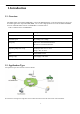
1.Introduction 1.1. Overview The HSPA+ Mini PCIe module DWM-800A , powered by MT6280 chipset, can be integrated into any devices for 3G mobile applications. It provides SMS, MMS, Call as well as high speed internet access to HSPA+and UMTS networks worldwide.
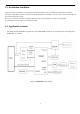
1.3. Installation Guidelines Careful planning and preparation of any installation will always benefit the end result, always read and follow all installation instructions. Follow ESD precautions and prepare an SD safe workspace for installation. Turn the power to the host off and ground yourself to dissipate static charge. Mount only in sockets and locations intended for Mini PCIe cards consult manufacturer on thermal management recommendations for the module mounted within the host. 1.4.
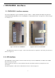
2. DWM-800A interfaces 2.1. DWM-800A interface summary The module DWM-800A supports multimode operation: HSPA+, UMTS (850/1900/2100 MHz) and quad-band GSM (850/900/1800/1900 MHz). The size of DWM-800A is 51mm*30mm*4.7mm. The appearance is shown in Figure 2-1 and Figure 2-2. Figure 2-2 The rear view of DWM-800A Figure 2-1 The front view of DWM-800A The MINI PCI-E is shown as in Figure , which is the main interface for application. RF antenna pad connector is shown as in Figure 2-1 . 2.1.1.
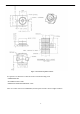
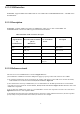
Figure 2-3 The sketch map of RF connector It’s required to use RF cable of which the insertion loss should comply with: • GSM850/900<1dB • DCS1800/PCS1900<1.5dB • UMTS2100/ UMTS1900/ UMTS850<1.
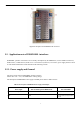
Figure 2-4 description of DWM-800A RF connectors 2.2. Application note of DWM-800A interfaces DWM-800A provides rich interfaces for secondary development by the MINI PCI-E, such as USIM card interface, USB interface, UART interface, PCM(Pulse Code Modulation) interface, I2C interface, power supply interface and so on. The detailed information will be described in the following sections. 2.2.1. Power supply and Ground The power supply input for DWM-800A module is listed as follows: DC +3.3V~+3.
2.2.2. USB interface 2.2.2.1. Description DWM-800A provides a high-speed USB interface by MINI PCI-E, which supports USB 2.0 protocol. The detailed information is given in Table 2-2. Table 2-2 DWM-800A USB interface description Signals of The correlative pins in SN. of MINI PCI-E Description MINI PCI-E DMUSB interface USB_HS_DM 36 USB Data- DP USB_HS_DP 38 USB Data+ GND GND 4,9,15,18,21,26,27,29,34,35,37, GND 43,50 2.2.2.2.
2.2.3. USIM interface DWM-800A supports USIM card in UMTS mode as well as SIM card in GSM/GPRS/EDGE mode,and UIM card in WCDMA mode. 2.2.3.1. Description DWM-800A provides USIM card interface by MINI PCI-E which can be used in both UMTS and GSM/GPRS/EDGE networks. The Table 2-3 gives more detailed information. Table 2-3 DWM-800A USIM card interface description Signals offered by The name of the correlative pins in USIM interface SN.
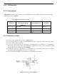
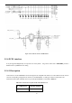
Figure 2-6 The reference circuit of USIM interface 2.2.4. PCM interface It can just support PCM(Optional). It can provide voice call by PCM ,using external audio codec . DWM-800A provides a UART interface by MINI PCI-E for debug. 2.2.4.1. Description PCM interfaces on the DWM-800A have been designed to be compatible with others so as to meet different needs. And we can make corresponding configuration for interfaces on the DWM-800A according to customer's requirements.
47 PCM_SYNC/PCM_IN 49 PCM_OUT/PCM_IN 51 PCM_IN/PCM_SYNC 2.2.5. SD card tntreface 2.2.5.1. Description There are seven pins for SD card in the MINI PCI-E. And the detailed information is given in Table 2-5 below. Table 2-5 DWM-800A SD card interface description pcie Pin.NO Signal name Description 13 SDC1_CMD SD Command/Response 17 SDC1_DATA0 SD Data 0 19 SDC1_DATA1 SD Data 1 23 SDC1_DATA2 SD Data 2 25 SDC1_DATA3 SD Data 3 31 SDC1_CLK SD Clock 32 VREG_SD SD Supply voltage 2.2.6.
I2C_SDA 32 2.6 I2C Interface SPI_SDI 3 SPI_SDO 5 2.6 Serial port control data output SPI_CS# 6 2.6 Serial port control Chip Select SPI_SCLK 7 2.6 Serial Port Bit Clock Serial port control data input 3. Electrical Characteristics and Safety Information 3.1. Absolute Maximum Ratings Absolute maximum rating for power supply and voltage on I/O pins of DWM-800A are list in table1 as follows.
The CPU(MT6280) power on sequence is as below: 3.3.
3.4. RF Exposure Compliance The antenna(s) used for this transmitter must be installed to provide a separation distance of at least 20 cm from all persons and must not be co-located or operating in conjunction with any other antenna or Transmitter.
The end user manual shall include all required regulatory information/warning as show in this manual. 4. Pins description of mini PCIE connector SN Definition Description Volt Remark The WAKE# signal is an open drain, active low signal that is driven low by a PCI Express Mini Card function to reactivate the PCI Express Link hierarchy’s main power rails and reference clocks. 1 WAKE_N OUTPUT 1.8 3 SPI_SDI Serial port control data input 1.8 5 SPI_SDO Serial port control data output 1.
20 W_DISABLE_N 2.6 22 EXT_RST_IN Reset 2.6 24 VDD3V3 POWER 3.3 26 GND Ground 28 Reserved Reserved 30 I2C_SCL I2C Clock 32* ** 34 The W_DISABLE# signal is an active low signal that when asserted (driven low) by the system shall disable radio operation. Reset module Power Supply Reserved For Future Use I2C_SDA/VMC_PMU I2C Data/VMC_PMU 2.6 I2C Interface 2.
- Reorient or relocate the receiving antenna. - Increase the separation between the equipment and receiver. - Connect the equipment into an outlet on a circuit different from that to which the receiver is connected. - Consult the dealer or an experienced radio/TV technician for help. FCC Caution: Any changes or modifications not expressly approved by the party responsible for compliance could void the user's authority to operate this equipment.