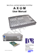
DIGITAL AUDIO MIXING SYSTEM A·X·U·M User Manual Version 2.5 - 2011-01-28 D&R Electronica Weesp BV Rijnkade 15B 1382GS Weesp The Netherlands Phone: +31 (0)294-418014 Fax: +31 (0)294-416987 Website: http://www.d-r.nl E-mail: info@d-r.
Dear Customer, Thank you for choosing the AXUM audio mixing system. Specialists in the field of Radio/TV Broadcast and audio production designed the AXUM. It is a system that is capable of working in a multitude of applications that need a 24-hour "On-Air"/Production system. To be able to improve our products we always value suggestions once you have become familiar with your system. We will certainly learn from your comments and very much appreciate you dropping us a mail at info@d-r.
A·X·U·M User Manual Version 2.5 - 2011-01-28 1 Table of contents 1 TABLE OF CONTENTS 3 2 PACKAGE CONTENTS 5 3 INTRODUCTION 6 4 SYSTEM OVERVIEW 7 4.1 SYSTEM PARTS 4.2 COMMUNICATION 4.3 FEATURES AND HIGHLIGHTS 4.4 PRINCIPLE OF OPERATION 4.4.1 AXUM system 4.4.2 Mixing console 7 9 10 11 11 11 5 CONTROL SURFACES 14 6 AXUM ENGINE 15 6.1 CONSOLE 1-4 CONFIGURATION 6.1.1 IP/Clock configuration 6.1.2 Global configuration 6.1.3 Mix buss configuration 6.1.4 Monitor buss configuration 6.1.
A·X·U·M User Manual 10.6 10.7 10.8 10.9 10.10 11 Version 2.5 - 2011-01-28 COBRANET IN/OUTPUT CARD ADAT IN/OUTPUT CARD HYBRID IN/OUTPUT CARD FIREWIRE IN/OUTPUT CARD DSP CARD PATCH PANELS 11.1 19” PATCH PANELS / BREAKOUT PANELS 11.2 W IRING 11.2.1 GPIO/Remote 11.2.2 MIC 11.2.3 Phones 11.2.4 Stereo line input and output 11.3 STANDARD RJ45 WIRING 11.3.1 GPIO TTL/Relay selection 12 12.1 12.2 12.3 12.
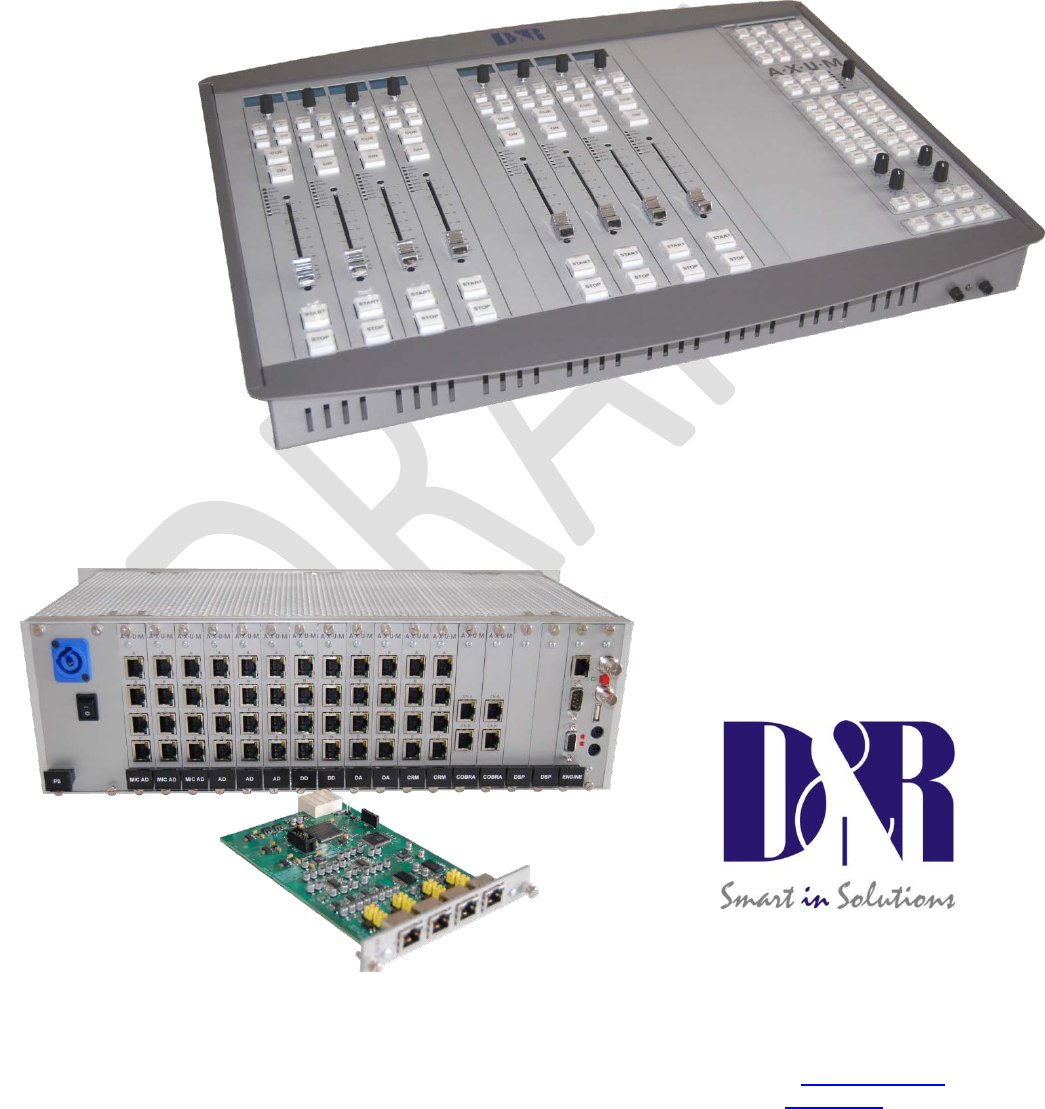
A·X·U·M User Manual Version 2.5 - 2011-01-28 2 Package Contents The AXUM package comes normally with the following parts inside: • AXUM Getting started document • AXUM System in the configuration you have ordered. One or more 19” IO-Racks with the I/O, DSP and power supply cards. Optional Control Surface(s) with external power supply. Optional patch panels. Optional RJ45 Shielded cables.
A·X·U·M User Manual Version 2.5 - 2011-01-28 3 Introduction This manual will give you an overview of the functionality of the AXUM digital audio system and all its features. It is advisable to read this manual at least once before touching any control, or even thinking about hooking up the system. We know that this is actually the first thing you want to do, but please do not and discipline yourself to read the manual first.
A·X·U·M User Manual Version 2.5 - 2011-01-28 4 System overview The Axum is a digital modular audio system that can solve your digital mixing/routing requirements in your broadcast studio or in your complete broadcast facility. The modular system can be used in all your mixing/routing applications like on-air broadcast, self-op, production and voice tracking. 4.
A·X·U·M User Manual Version 2.5 - 2011-01-28 Figure 1: Basic system layout AXUM from D&R - Phone: +31 294 418014 - E-Mail: info@d-r.
A·X·U·M User Manual Version 2.5 - 2011-01-28 4.2 Communication All control communication takes place with MambaNet and gives the surface flexibility and power to the AXUM digital audio system. To understand the AXUM digital audio system it would help to know some principles of MambaNet. MambaNet definitions: - Objects A fader, switch will have to trigger an action in the AXUM digital audio system. In MambaNet, we call these faders and switches ‘objects’.
A·X·U·M User Manual Version 2.5 - 2011-01-28 4.3 Features and highlights Because the AXUM digital audio system is highly flexible, you can make many solutions for your mixing and routing.
A·X·U·M User Manual Version 2.5 - 2011-01-28 4.4 Principle of operation 4.4.1 AXUM system The AXUM system will be build up around the matrix/router that gives a lot of routing flexibility. Up to 4 DSP cards can be inserted to create mixing power as requested.
A·X·U·M User Manual Version 2.5 - 2011-01-28 4.4.2.1 Sources Each module can receive audio from the matrix using so called ‘sources’. A source is given a name, left/right physical input and some additional settings (think of phantom, pad, redlight settings). For example if we make source ‘MIC1’ with phantom on we can route this to module 1 and/or module 13. So the MIC 1 is used at console 1 but also at console 2 (or 3). 4.4.2.2 Destinations Audio is sent to physical outputs by so called ‘destinations’.
A·X·U·M User Manual - Version 2.5 - 2011-01-28 When a source is selected (can also be in the startup-defaults) the corresponding processing preset is loaded. When a module preset is loaded, the complete module settings can be preset. With the console preset you are able to change: module-settings , buss master en monitor buss settings. AXUM from D&R - Phone: +31 294 418014 - E-Mail: info@d-r.
A·X·U·M User Manual Version 2.5 - 2011-01-28 5 Control Surfaces The engine will recognize the control surfaces of the AXUM digital audio system as ‘nodes with objects’. Each object can connect to an engine (mixing console) function. Below you see an example of a control surface and a short description of the node/object structure.
A·X·U·M User Manual Version 2.5 - 2011-01-28 6 AXUM Engine The engine of the Axum drives all audio processing/routing and from the surfaces and remote locations, it can be controlled using MambaNet. Therefore it is required that you setup the engine/system with your settings before it will work according your requirements. Of course, we deliver the system in a default configuration that will cover 90% of the functionality you wish.
A·X·U·M User Manual Version 2.5 - 2011-01-28 6.1 Console 1-4 configuration This pages shows all configuration possibilities to setup your console 1-4. Your system is preconfigured but you may step through the menus for personal adjustments. Figure 5: Console 1-4 configuration AXUM from D&R - Phone: +31 294 418014 - E-Mail: info@d-r.
A·X·U·M User Manual 6.1.1 Version 2.5 - 2011-01-28 IP/Clock configuration Figure 6: IP/Clock configuration 6.1.1.1 IP Here you can setup the network settings to be compatible with the required settings in your situation and you can set the time zone to where you are. It’s possible to change the IP, subnet, gateway and DNS server address by clicking on the address. For more information on IP addressing: http://en.wikipedia.org/wiki/IP_address WARNING: These setting become active after reboot. 6.1.1.
A·X·U·M User Manual Version 2.5 - 2011-01-28 The AXUM uses the NTP protocol for accurate clock synchronization. In the section ‘current’ you find the IP address of the used ‘clock master’ and its ‘stratum’. For more information on NTP: http://en.wikipedia.org/wiki/Network_Time_Protocol When IP and DNS settings are setup correct, the AXUM will automatically synchronize to a pool of time servers. The AXUM is also able to use a GPS receiver via USB for time synchronization.
A·X·U·M User Manual 6.1.2 Version 2.5 - 2011-01-28 Global configuration Some overall system settings can be filled in on this webpage. Figure 7: Global configuration • Sample rate You can select a sample rate of 32 kHz, 44.1 kHz en 48kHz. According to this setting, the filters are setup so you have to make sure to select the sample rate you work with. Also when using an external clock. • Extern(al) clock If you want to use the external clock (Frame clock in) you can turn it on here.
A·X·U·M User Manual 6.1.3 Version 2.5 - 2011-01-28 Mix buss configuration You have to setup the busses to create the names, console assignment and functionality of the Busses. Here we see the setup for a single console buss setup: Figure 8: Buss configuration • Label The name given to this buss. • 2 Mono busses It is possible to make 2 mono busses from one stereo buss. All buss-sends, to this buss, on the module’s will now include stereo to mono summing.
A·X·U·M User Manual 6.1.4 Version 2.5 - 2011-01-28 Monitor buss configuration Per DSP card, you have 4 stereo monitor busses that can be used. They need a name, console assignment and configuration so they can work properly: Figure 9: Monitor buss configuration • Label Here you give a name to this monitor buss • Interlock Yes means only one source is active at the same time, on this monitor buss.
A·X·U·M User Manual 6.1.5 Version 2.5 - 2011-01-28 Source configuration The 19” rack unit can accept various I/O cards. These inserted I/O cards can accept audio in various formats. This is because the audio connected to the I/O cards can have different channel relations (mono, stereo). To create a user readable label you have to configure sources. Such a source is the entity you can select to be the input of your module in the mixing console.
A·X·U·M User Manual Version 2.5 - 2011-01-28 • Processing preset If this source is selected on a module, by the ‘source select’ function (not via module or console preset), this processing preset is ‘set’ on the module. • Trigger start Here you can configure how the source start/stop change is triggered: - Dedicated, the module fader and on are not triggering start/stop only the dedicated start/stop controllers. - Module fader on, the fader on will trigger the start as well.
A·X·U·M User Manual 6.1.6 Version 2.5 - 2011-01-28 Extern source configuration Each DSP card can handle four stereo monitor busses (with 4 DSP cards a max of 16 stereo monitor busses is possible). For each DSP card you can configure 8 external stereo sources, beyond the 16 stereo mixing busses which are fixed available in the monitor section. Figure 11: External source configuration • Safe Extern source can be configured to be ‘interlock safe’.
A·X·U·M User Manual 6.1.7 Version 2.5 - 2011-01-28 Destination configuration The 19” rack unit can accept various I/O cards. With these cards, you can send audio from the Axum digital audio system to the audio format you require. Because the audio connected to the I/O cards can have different channel relations (mono, stereo) a combination has to be made. A user readable label has to be created to configure destinations.
A·X·U·M User Manual Version 2.5 - 2011-01-28 (this field is only available when the destination-level function is also assigned to an object; e.g. via rack configuration) • Default signal from This destination/output will send audio from the default selected source (except if a N-1 is active, then automatically the N-1 signal is selected). You can choose: - Input sources (Mic, line, dig etc. etc.
A·X·U·M User Manual 6.1.8 Version 2.5 - 2011-01-28 Talkback configuration This page makes it possible to select the sources for the 16 talkback busses available in the AXUM. A talkback buss may be summed/switched to any destination of the AXUM system, this will not require any DSP resources. Figure 13: Talkback configuration • Source Here you can select which signal routes to a talkback buss. You can choose: - Input sources (Mic, line, dig etc. etc.
A·X·U·M User Manual 6.1.9 Version 2.5 - 2011-01-28 Processing presets It is possible to set the module processing when a source is selected (via ‘source select’ or a module preset) , the information for this functionality is stored in the processing presets. Figure 14: Processing presets • Nr Here you can reposition the preset to make the list in a convenient order. • Label Name of the preset. • Settings. Shows a new page where you can configure the preset.
A·X·U·M User Manual 6.1.9.1 Version 2.5 - 2011-01-28 Settings All processing parameters can be configured in the processing preset settings webpage Figure 15: Processing preset settings • Override module If set to no, the module setting will not be affected by this preset. If set to yes, this preset will change the settings of the module for the corresponding processing section (Digital gain, Low cut etc. etc.
A·X·U·M User Manual Version 2.5 - 2011-01-28 For EQ and dynamics, a popup window is shown. Here you can set multiple values. Figure 16: Processing preset EQ/Dynamics settings EQ Range Maximal adjustment you may generate with this band. EQ Level Level of the band that this preset will set. The value must be within the EQ Range EQ Frequency Frequency of the band that this preset will set. The frequency range is 20-20000 Hz. EQ Bandwidth Bandwidth of the band that this preset will set.
A·X·U·M User Manual Version 2.5 - 2011-01-28 6.1.10 Module assignment Modules can be assigned to one of the 4 consoles, after this and a correct assignment of the busses (in buss configuration) to the consoles you may click ‘generate’ to make a correct assignment configuration. Afterwards you can override the generate assignments by clicking the ‘y’/’n’ fields. For example you can create a buss that is available to all consoles.
A·X·U·M User Manual Version 2.5 - 2011-01-28 6.1.11 Module configuration The module configuration makes it possible to give modules a default setting (after powering on) and you can also configure module presets 1A/1B, 2A/2B, 3A/3B, 4A/4B. Figure 18: Input module configuration • Console Shows to which console the module is assigned. • Preset 1A/1B, 2A/2B, 3A/3B, 4A/4B Shows the source and processing preset selected for corresponding module preset.
A·X·U·M User Manual Version 2.5 - 2011-01-28 6.1.11.1 Module configuration page On this page you can setup the default module configuration, used at startup if programmed default is selected in global configuration. If you have made your settings and you would like to copy them to all modules in this console (for example if you want to use the same EQ center frequencies) you can simply hit ‘To all console x modules’ after you made and checked the settings on the current module.
A·X·U·M User Manual Version 2.5 - 2011-01-28 6.1.11.2 Module preset 1A/1B, 2A/2B, 3A/3B, 4A/4B Here you select the source, processing preset and routing preset that is used when module preset 1A/1B, 2A/2B, 3A/3B, 4A/4B is selected. After a click on ‘routing’ a popup appears with the routing possibilities (this depends on the console assignment). • Source If you click here a popup appears with a list of all available sources. Select the source you want to use in this module preset.
A·X·U·M User Manual • Version 2.5 - 2011-01-28 Ignore module state When presets are recalled, it checks the module state to prevent recalling ‘onair’ signals. The preset will wait till the module is switched off air. If the ignore module state function is switched to yes, the presets will not check the module state and forces the recall to be done always! 6.1.11.3 Processing These are the programmed processing defaults for the modules.
A·X·U·M User Manual Version 2.5 - 2011-01-28 6.1.11.4 Routing The field ‘Use at source select’ determines if the default module routing is used when a source is assigned via the module source select functionality . The following routing sections are available: • Buss level You may predefine the send level of a module to the busses (e.g. Aux send). • Buss status You have to setup the startup status for the busses. With this setting you set the buss routing (e.g. Program on/off or CUE on/off).
A·X·U·M User Manual Version 2.5 - 2011-01-28 6.1.12 Mix/monitor buss presets It is possible to make mix/monitor buss presets to make sure the correct buss master states and levels are set for different programs. Also you can make sure the required monitor buss selection is made. Figure 21: Mix/monitor buss presets • Nr Here you can reposition the preset to make the list in a convenient order. • Label Name of the preset. • Settings. Shows a new page where you can configure the preset.
A·X·U·M User Manual Version 2.5 - 2011-01-28 6.1.12.1 Settings On this page you can set the required levels and state for all busses and monitor busses which are used in the mix/monitor buss preset. Figure 22: Mix/monitor buss preset settings 6.1.12.2 Mix buss settings • Console Displays the console where this mix buss is assigned to. • Use When set to ‘yes’ the settings for this mix buss overrides the current mix settings if the preset is loaded.
A·X·U·M User Manual • Version 2.5 - 2011-01-28 State This must be set to ‘on’ to force this monitor-buss routing to be active. When it is set to ‘off’ the monitor-buss routing will be forced to go ‘off’. AXUM from D&R - Phone: +31 294 418014 - E-Mail: info@d-r.
A·X·U·M User Manual Version 2.5 - 2011-01-28 6.1.13 Console presets To recall a complete console you use the console presets, what exactly is recalled is depending on the underlying configuration of: - Source configuration - Processing presets - Module configuration - Mix/monitor buss presets When a console preset is recalled it will set all modules to the module preset ‘A’-‘H’ as configured. Secondly it will load the Mix/monitor preset as given in the console preset.
A·X·U·M User Manual Version 2.5 - 2011-01-28 6.1.14 Surface configuration You can see an overview of the boards in the surface(s) on this page. These are grouped together, like their physical layout. Figure 24: Surface configuration • MambaNet Address Show information on the internal used MambaNet addresses • Node name Logical name of the node • Default Number of objects that have a default value set. • Config Number of objects that are configured to an engine function.
A·X·U·M User Manual Version 2.5 - 2011-01-28 same or a different node (of the same type). When you import Module 5-8 with an offset of -4 the configuration will be as you expect Module 1-4. • User level Here you can define to which console the module belongs in terms of user level. The user level depends on the user logged on to the AXUM system. If ‘None’ is selected this node will always have full access.
A·X·U·M User Manual Version 2.5 - 2011-01-28 6.1.15 Rack configuration You can see an overview of the cards in the rack on this page. You can find information like the slot number, MambaNet address, card name, number of inputs and outputs. The link Configure will go to a page for connecting objects of the card to Axum engine’s functions. You can consider this as the remote control configuration.
A·X·U·M User Manual Version 2.5 - 2011-01-28 • User level Here you can define which console user level the I/O card will use (e.g. for its GPIs). • Configure The page shown below gives an indication how the CRM output level objects connect to the Speaker level engine functions. By following the links, you can reconfigure the functions that connect to the objects. The sensor and actuator data types determine which function assigns to the object.
A·X·U·M User Manual Version 2.5 - 2011-01-28 6.1.16 Source pools You can see an overview of the source pools on this page. A source pool may be assigned to a user to give them a comfortable source list for selection from the control surface. Figure 28: Source pool configuration • Type Type of the source. • Label Name of the source. • Source pool Per console there are 2 source pools A/B If y is selected the source will be available in the selected source pool.
A·X·U·M User Manual Version 2.5 - 2011-01-28 6.1.17 Preset pools You can see an overview of the preset pools on this page. A preset pool may be assigned to a user to give them a comfortable source list for selection from the control surface. Figure 29: Preset pool configuration • Label Name of the preset. • Preset pool Per console there are 2 preset pools A/B If y is selected the preset will be available in the selected preset pool. If n is selected the preset won´t be available.
A·X·U·M User Manual Version 2.5 - 2011-01-28 6.1.18 Users You can see an overview of the users on this page. You can see the user level/preset per user and per console. Figure 30: User configuration • Login Here you can login as a user to the selected console. • Write Here you can write the selected user to a plugged in chipcard. • Active account The account that is currently active in this console (this may be different from the chipcard if overruled by software).
A·X·U·M User Manual Version 2.5 - 2011-01-28 • Console preset It is possible to select a console preset which will be loaded if the user logs in. • Pool Per console you can select which preset and which source pool the user may use. Per pool you can choose between A, B or all. (see also 6.1.16 Source pools and 6.1.17 Preset pools) • Delete When you click on this column the user will be deleted.
A·X·U·M User Manual Version 2.5 - 2011-01-28 6.2 System configuration If you browse to the url http://192.168.0.200/system (where 192.168.0.200 should be your local AXUM IP address) you have a system menu with give some management/service possibilities. Figure 31: Service menu • MambaNet node overview Will show all nodes that are found in the local Ethernet network. • Generate sources WARNING: this function deletes all sources and their configuration.
A·X·U·M User Manual 6.2.1 Version 2.5 - 2011-01-28 MambaNet node overview This pages shows all nodes found in the local Ethernet network. Also nodes that are not online can be seen as ‘grayed out’ nodes. Figure 32: MambaNet node overview • Address This is the MambaNet address used in this setup. This address is used for all communication and configuration. • UniqueID This shows the ‘ManufacturerID:ProductID:UniqueID’ in hexadecimal format.
A·X·U·M User Manual Version 2.5 - 2011-01-28 which is most easy for systems with only one engine. • Parent Easy node can store its parent node so we can determine the physical-location of nodes. • User level Here you can define which console user level the node will use. • Default, Config and Objects This column shows the numbers of objects and how many have a default value or configuration • Delete/Refresh Grayed out nodes may be deleted by pressing the delete image.
A·X·U·M User Manual 6.2.2 Version 2.5 - 2011-01-28 Templates The learner continuously checks for unknown nodes. When a unknown node is found it will read the object information and store it in the database. A template is unique by: ManufactureID, ProductID and Major Firmware Revision. Figure 33: Node templates • Count Shows the number of objects that are located in this template. • Delete When because of a failure a template is wrong you may delete it so the learner will read the information again.
A·X·U·M User Manual 6.2.3 Version 2.5 - 2011-01-28 Predefined node configurations The configurations that are exported are listed here. When you mistakenly did export a configuration you may delete it from here. Figure 34: Stored configurations • Config Config gives the number of configured objects that are stored. • Default Default gives the number of configured defaults that are stored. AXUM from D&R - Phone: +31 294 418014 - E-Mail: info@d-r.
A·X·U·M User Manual 6.2.4 Version 2.5 - 2011-01-28 Engine functions This is a list of all available engine functions. Figure 35: Engine functions • Pos Here it is possible to reposition the functions for easier/faster access in the surface/rack configuration menu’s • Type Shows the group the functions belongs to and determines which number range is used.
A·X·U·M User Manual Version 2.5 - 2011-01-28 • Xmt The transmit column shows which datatype is required at the object-actuator to be able to receive data from the engine. • Label This label will be used if default function label for remote software applications. It can be changed here globally. In the surface/rack configuration you may give labels per configured object-function.
A·X·U·M User Manual 6.2.6 Version 2.5 - 2011-01-28 Change web accounts The webserver requires authentication. On this page you change the username and password. Figure 37: Change password AXUM from D&R - Phone: +31 294 418014 - E-Mail: info@d-r.
A·X·U·M User Manual Version 2.5 - 2011-01-28 7 Surface(s) website To set the time displayed in the meter of the console. Simply enter the IP address of the console in your browser and log-on to the configuration pages. By default the IP Address is: http://192.168.0.234 (at first time startup you can use a network or cross wire with a static IP given to your network interface, e.g. 192.168.0.10).
A·X·U·M User Manual Version 2.5 - 2011-01-28 7.1 IP/Clock configuration Figure 39: IP/Clock configuration 7.1.1.1 IP Here you can setup the network settings to be compatible with the required settings in your situation and you can set the time zone to where you are. It’s possible to change the IP, subnet, gateway and DNS server address by clicking on the address. For more information on IP addressing: http://en.wikipedia.org/wiki/IP_address 7.1.1.
A·X·U·M User Manual Version 2.5 - 2011-01-28 7.1.1.3 Clock To change the time zone, click on the used time zone (in our example ‘Europe/Amsterdam’). You can select the desired time zone in the list box. The AXUM uses the NTP protocol for accurate clock synchronization. In the section ‘current’ you find the IP address of the used ‘clock master’ and its ‘stratum’. For more information on NTP: http://en.wikipedia.
A·X·U·M User Manual Version 2.5 - 2011-01-28 8 Block diagrams – Must be created With all configuration options, it is possible to make many different systems using a single I/O rack. We will show some example block diagrams on possible setups within an Axum system. 32 stereo module, 16 stereo buss and 4 stereo monitor buss console: Note: These diagrams will follow in future manuals, sorry AXUM from D&R - Phone: +31 294 418014 - E-Mail: info@d-r.
A·X·U·M User Manual Version 2.5 - 2011-01-28 9 I/O Rack description The AXUM digital audio system has a 19” rack (for 21 slots) that requires at least one power supply (3 slots) and one engine card (2 slots). You then have space for a maximum of 16 in and output cards. Because the AXUM is a modular system it is up to you how many in and output cards are necessary to do the job.
A·X·U·M User Manual Version 2.5 - 2011-01-28 9.1 Power supply At the far left in the I/O RACK is the position where the power supply Card is inserted; an optional second power supply card can be inserted alongside this first one. With two power supplies, you have created automatic power supply redundancy. The LED will blink green to show the power supply is up and running. At failure of the local power, this LED activity will be blinking red or not blinking at all.
A·X·U·M User Manual Pin 1 GND Pin name Centre GND Version 2.5 - 2011-01-28 Function Frame Clock in Ground Frame Clock in Comment 32kHz, 44.1kHz, 48kHz, +/- 100ppm, +5V TTL, switchable 75Ohm terminator. Table 9-1: Frame clock input BNC Pin 1 Pin name Centre GND GND Function Frame Clock Out Ground Frame Clock out Comment 32kHz, 44.1kHz, 48kHz, +5V TTL, imp.
A·X·U·M User Manual Pin 1 6 2 7 3 8 4 9 5 S Pin name DCD DSR RD RTS TD CTS DTR RI GND Shield Version 2.5 - 2011-01-28 Function Carrier Detect Data Set Ready Receive Data Request To Send Transmit Data Clear To Send Data Terminal Ready Ring Indicator Ground Ground Table 9-6: RS232 9pin SUB-D connector Pin 1 2 3 6 5 4 7 8 S Con.
A·X·U·M User Manual Version 2.5 - 2011-01-28 9.3 GPIO In rack configuration you can connect objects of MambaNet nodes to AXUM engine functions. Here you can also configure the GPIO objects of your I/O cards (MambaNet nodes). By following the links, you can reconfigure the functions that connect to the objects. The sensor and actuator data types determine which function assigns to the object. For a complete list of the functions, you can look up chapter 20 Appendix C – Engine functions. 9.3.
A·X·U·M User Manual Version 2.5 - 2011-01-28 or 1). A value of ‘1’ makes sure that if the GPI is +5V the function is made active. The value ‘0’ makes sure that if the GPI is 0V the function is made active. When you submit an empty box the object returns to the startup default value. 9.3.3 GPO Figure 43: GPO configuration • Default The gray value is the startup default, this may be changed by assigning a custom value(0 or 1). A value of ‘1’ makes sure the GPO is active at startup.
A·X·U·M User Manual Version 2.5 - 2011-01-28 The value must be between 0 – 250, where 0 is a continuous signal and 1 - 250 is the pulse width in milliseconds. When you submit an empty box the object returns to the startup default value. 9.3.5 GPO Active-state Figure 45: GPO Active-state configuration • Default The gray value ‘1’ is the startup default, this may be changed by assigning a custom value (0 or 1).
A·X·U·M User Manual Version 2.5 - 2011-01-28 10 Available I/O rack cards Depending on your audio-connections, you can select the I/O cards. The next paragraphs will give you a detailed overview on the currently available cards. 10.1 MIC input card There are four balanced MIC inputs available on each card. Each RJ45 connector represents a MIC input and two GPIO’s which can be connected to the 19” patch panels with a shielded twisted pair (STP) cable.
A·X·U·M User Manual Version 2.5 - 2011-01-28 10.2 Line input card There are four balanced stereo line inputs available on each card. Each RJ45 connector represents a stereo line input and two GPIO’s which can be connected to the 19” patch panels with a shielded twisted pair (STP) cable. For each GPIO you can choose, by way of a hardware jumper on de board, between TTL Input/output or Photo-MOS relay output see chapter 11.3.1 GPIO TTL/Relay selection. For software configuration see chapter 9.3 GPIO.
A·X·U·M User Manual Version 2.5 - 2011-01-28 10.3 Digital in/output card (optional SRC) There are four balanced digital inputs and outputs available on each card. Each RJ45 connector represents a stereo line input and two GPIO’s which can be connected to the 19” patch panels with a shielded twisted pair (STP) cable. There is also a card available with built in sample rate converters (SRC).
A·X·U·M User Manual Version 2.5 - 2011-01-28 10.4 Line output card There are four balanced stereo line outputs available on each card. Each RJ45 connector represents a stereo line output and two GPIO’s which can be connected to the 19” patch panels with a shielded twisted pair (STP) cable. For each GPIO you can choose, by way of a hardware jumper on de board, between TTL Input/output or Photo-MOS relay output see chapter 11.3.1 GPIO TTL/Relay selection. For software configuration see chapter 9.3 GPIO.
A·X·U·M User Manual Version 2.5 - 2011-01-28 10.5 CRM output card There are four stereo outputs available on this card. RJ45 connector A&B represents the CRM stereo line output. RJ45 connector C&D represents the stereo phones outputs. Each RJ45 connector has also two GPIO’s which can be connected to the 19” patch panels with a shielded twisted pair (STP) cable. This stereo output card has some special functions: - Analog level and mute functionality. - Headphone amplifiers.
A·X·U·M User Manual Version 2.5 - 2011-01-28 10.6 CobraNet in/output card This CobraNet In/output card converts the CobraNet network signals into digital audio so it can be processed in the AXUM system’s 19” inch rack. The CobraNet In/out card can be ordered with various channel counts, please contact your sales contact for the available options. Pin 1 2 3 6 5 4 7 8 S Con.
A·X·U·M User Manual Version 2.5 - 2011-01-28 10.7 ADAT in/output card This ADAT In/output card converts the ADAT optical signals into digital audio which can be received by the 19” inch rack. The ADAT card has to run synchronous with the connected devices, allowed sample rate frequencies are 32kHz, 44.1kHz or 48kHz. AXUM from D&R - Phone: +31 294 418014 - E-Mail: info@d-r.
A·X·U·M User Manual Version 2.5 - 2011-01-28 10.8 Hybrid in/output card Pin connection Hybrid card. Pin RJ14 Pin RJ11 Pin name 1 R2 + 2 1 R1 3 2 T1 + 4 T2 - Pair 2 1 2 Function Comment To Handset R + From Wall RFrom Wall T+ To Handset T - Table 10-8 Hybrid Rj14 (Telephone) connection This Hybrid In/output card converts the analog telephone signals into digital audio so it can be processed by the 19” inch rack. The Hybrid card allows external callers to be connected to the AXUM.
A·X·U·M User Manual Version 2.5 - 2011-01-28 10.9 Firewire in/output card This Firewire In/output card converts the Firewire digital signals into digital audio which can be processed by the 19” inch rack. The Firewire card has to run synchronous with the connected devices, allowed sample rate frequencies are 32kHz, 44.1kHz or 48kHz. WDM and ASIO Drivers are available. Via WDM driver the device is seen as a single multi-channel WDM device (8 channels). Normally this means your card acts like a 7.
A·X·U·M User Manual Version 2.5 - 2011-01-28 10.10DSP card The DSP card adds mixing capabilities to your 19” rack. In combination with the Axum engine, this card gives you 32 stereo processing channels to create a mixing desk. The system may be loaded with four DSP cards, which generates a mixing console with 128 stereo channels. The ACT(ive) LED blinks when this card functions properly. AXUM from D&R - Phone: +31 294 418014 - E-Mail: info@d-r.
A·X·U·M User Manual Version 2.5 - 2011-01-28 11 Patch panels All distribution of audio within the AXUM digital audio system is with shielded twisted pair cable. The Breakout 19” panels, you need to connect equipment use standard audio connectors. 11.1 19” Patch panels / Breakout panels The AXUM 19” Break out patch panels convert the RJ45 Shielded connection to the industry standard connectors such as XLR and Jack.
A·X·U·M User Manual Version 2.5 - 2011-01-28 11.2 Wiring 11.2.1 GPIO/Remote The remote jack connects to all kinds of remote in-/outputs. Such as remote start/stop, external red lights or cough. The function of the remote jack depends on the I/O card and function setup for this GPIO. The software determines its function and where it is connected to.
A·X·U·M User Manual Version 2.5 - 2011-01-28 GPO connection example for remote START Pioneer CD-player. 11.2.2 MIC The MIC input connects microphones to the AXUM. The AXUM Mic Rack Module supports 48 volts DC phantom power if it is switched on in the software. Female XLR Pin Function Comment 2 +Audio Audio in phase 3 –Audio Audio out phase 1 Shield Ground Table 11-1: MIC patch panel XLR wiring 11.2.3 Phones The Phones jacks connect headphones to the AXUM console.
A·X·U·M User Manual Version 2.5 - 2011-01-28 11.2.4 Stereo line input and output The line I/O jack patch panel houses female jack connecters, the line I/O XLR patch panel houses XLR type connectors (male or female). Female XLR Male XLR Name 2 3 1 Function +Audio -Audio Pinning Audio in phase Audio out phase Shield Ground Table 11-3: Line I/O patch panel XLR wiring 11.
A·X·U·M User Manual • Version 2.5 - 2011-01-28 Relay out (no input available). this is selected by GPIO1 jumpers in the place 23 and GPIO2 jumpers in place 56. These jumpers are located on the I/O cards, close to the RJ45 connectors. Pin 1 2 3 6 5 4 Con.
A·X·U·M User Manual Line inputs Version 2.5 - 2011-01-28 : Electronically balanced : Input impedance 10k Ohm : input sensitivity +6dBu, maximum input +26dBu (+/- 20dB gain range). : CMRR Line inputs: 30dB @ 1 kHz, maximum gain : Transformer balancing is optional on the patch panels Line Outputs : Electronically balanced : Output impedance 56R Ohm.
A·X·U·M User Manual Power supply Version 2.5 - 2011-01-28 TM TM : Neutrik PowerCon (delivered in the package). : 100-240 Volt, 50/60Hz (1.7A Max) 12.
A·X·U·M User Manual Version 2.5 - 2011-01-28 13 List Of Figures Figure 1: Basic system layout ................................................................................................................. 8 Figure 2: MambaNet logo ........................................................................................................................ 9 Figure 3: 12 fader control surface .........................................................................................................
A·X·U·M User Manual Version 2.5 - 2011-01-28 14 List Of Tables Table 9-1: Frame clock input BNC ........................................................................................................ 63 Table 9-2: Frame clock output BNC ...................................................................................................... 63 Table 9-3: VGA 15p D-Sub connector ...................................................................................................
A·X·U·M User Manual Version 2.5 - 2011-01-28 15 Declaration Of Conformity DECLARATION OF CONFORMITY Manufacturers Name: D&R Electronica Weesp B.V.
A·X·U·M User Manual Version 2.5 - 2011-01-28 16 Product Safety This product is been manufactured with the highest standards and is double-checked in our quality control department for reliability in the "HIGH VOLTAGE" section. CAUTION • Never remove any panels, or open this equipment. • No user serviceable parts inside. • Equipment power supply must be grounded at all times. • Only use this product as described, in user manual or brochure.
A·X·U·M User Manual Version 2.5 - 2011-01-28 17 Disclaimer Due to a policy of continuous product improvement, D&R Electronica Weesp B.V. reserves the right to change specifications, appearance and performance without prior notice. Since the use of this information and the conditions by which the products are used are beyond the control of D&R Electronica Weesp B.V.
A·X·U·M User Manual Version 2.5 - 2011-01-28 18 Appendix A - Network design for AXUM The platform AXUM design is according to the OSI-Model and makes use of protocols on different levels. It is important to understand the philosophy on the different levels in networking and the way the AXUM implemented this. With this knowledge, you can make an advanced network setup within your studio(s) give you possibilities for: - Remote configuration - Remote service - Connecting multiple AXUM racks to internet.
A·X·U·M User Manual Version 2.5 - 2011-01-28 18.2.2 MambaNet example 2 - MambaNet over layer 3(UDP or TCP) Is used for the Axum internal communication, where you have to think of fader, knob data etc. etc. - Configuration over layer 3 (IP) Is used for the Axum configuration and service access. The MambaNet over UDP (and TCP) is connection oriented. With the destination IP address you determine to which rack this surface hooks up. 18.
A·X·U·M User Manual Version 2.5 - 2011-01-28 ONLY IP AXUM 1 LAN AXUM 2 LAN OFFICE LAN In the next chapters we show you some solutions how to implement this structure. Because these structures are well known in network-technologies there are also several different solutions where you can pick the most interesting/efficient for you. AXUM from D&R - Phone: +31 294 418014 - E-Mail: info@d-r.
A·X·U·M User Manual Version 2.5 - 2011-01-28 18.3.1 Practical solution 1: Physical separated switches and IP router If you give the AXUMs and OFFICE networks their own physical Ethernet switch, you ofcourse have good ‘level 2’ (Ethernet) separation. If you additional hook up an IP router to the Ethernet switches it is possible to make IP routes between the different networks, without ‘level 2’ interference.
A·X·U·M User Manual Version 2.5 - 2011-01-28 18.3.2 Practical solution 2: single managed level 3 switch/router When you select an level 3 managed switch with the following features: - Port VLAN - Inter VLAN routing (IP) (VLAN stands for Virtual Local Area Network) It will be possible to hook up all your network equipment to the same switch and configure the switch so it functions equal to ‘Practical solution 1’. Therefore you have to make 3 VLANs and make correct Inter VLAN IP routes.
A·X·U·M User Manual Version 2.5 - 2011-01-28 18.3.3 Practical solution 3: Physical separated switches and PCs if IP router It is also possible to have a PC configured to do IP routing. Of course, it is necessary to have two or more network cards before you can make IP routing. In our example we will show an setup with two PCs with two network card.
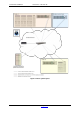
A·X·U·M User Manual Version 2.5 - 2011-01-28 18.4 Network design (MambaNet over Layer 3) When using MambaNet over UDP or TCP it is possible to use multiple racks in a single network. It is important you realize that a single surface may connect to a single rack only. Layer 2 network (Ethernet), also office network. MambaNet cloud 2 UDP to 192.168.0.100:34848 AXUM Surface IP :192.168.0.201 Mask : 255.255.255.0 GW : 192.168.0.1 IP :192.168.0.10 Mask : 255.255.255.0 GW : 192.168.0.1 AXUM Rack IP :192.
A·X·U·M User Manual Version 2.5 - 2011-01-28 18.5 IP subnets and IP routes When you have made your network design, where the level 2 is separated and you IP routing is available you need to care about correct IP addressing, subnets and routes. Altough your internal AXUM configuration will function without problem. These IP addressing are necessary for: - Configuration - NTP time synchronization - Remote access. First you have to define a different subnet for each separated ‘level 2’ network.
A·X·U·M User Manual Version 2.5 - 2011-01-28 18.6 Remote access Now you have setup your network and IP addressing correct you have to do one last step before you can remote access your AXUM systems. There are also different methods for remote access, for all methods you have to check the manual of your modem/router how to setup. 1) VPN connection Virtual Private Network is a secure way to have remote access and you can use the internal IP numbers at your remote location.
A·X·U·M User Manual Version 2.5 - 2011-01-28 19 Appendix B – Surface service If you browse to the url http://192.168.0.234/service (where 192.168.0.234 should be your local console IP address) you have a service menu with give some management possibilities. Figure 51: Console service menu • Package versions Shows the packages, version and build/install date. • Download backup Downloads a file which is a complete image of the internal flash disk.
A·X·U·M User Manual Version 2.5 - 2011-01-28 19.1 Package versions This page shows the installed packages with their version number, build and install date. Figure 52: Package versions AXUM from D&R - Phone: +31 294 418014 - E-Mail: info@d-r.
A·X·U·M User Manual Version 2.5 - 2011-01-28 19.2 Change password The webserver requires authentication. On this page you change the username and password. Figure 53: Change password AXUM from D&R - Phone: +31 294 418014 - E-Mail: info@d-r.
A·X·U·M User Manual Version 2.5 - 2011-01-28 19.3 Upload logo On this page you can upload you own logo which will appear on the meter screen. Figure 54: Logo upload • Logo upload Choose the logo you want to use and upload it to the website. The logo must be a .png image. It will be resized to 256x150 pixels. After a reboot the logo will be visible on the meter screen from the AXUM console. AXUM from D&R - Phone: +31 294 418014 - E-Mail: info@d-r.
A·X·U·M User Manual Version 2.5 - 2011-01-28 20 Appendix C – Engine functions The engine houses all mixing console functions and is able to connect various objects to its function as has been described in the previous chapters. Below we give a list of all available functions within the engine. 20.1 Modules If four DSP cards are inserted, it is possible to have 128 modules (32 stereo modules per DSP card).
A·X·U·M User Manual Function name EQ Band 2 Bandwidth reset EQ Band 2 Type EQ Band 3 Level EQ Band 3 Frequency EQ Band 3 Bandwidth EQ Band 3 Level reset EQ Band 3 Frequency reset EQ Band 3 Bandwidth reset EQ Band 3 Type EQ Band 4 Level EQ Band 4 Frequency EQ Band 4 Bandwidth EQ Band 4 Level reset EQ Band 4 Frequency reset EQ Band 4 Bandwidth reset EQ Band 4 Type EQ Band 5 Level EQ Band 5 Frequency EQ Band 5 Bandwidth EQ Band 5 Level reset EQ Band 5 Frequency reset EQ Band 5 Bandwidth reset EQ Band 5 Type E
A·X·U·M User Manual Function name Fader and on inactive Fader and on active/inactive Fader on Fader off Fader on/off Buss 1/2 level Buss 1/2 level reset Buss 1/2 on Buss 1/2 off Buss 1/2 on/off Buss 1/2 pre Buss 1/2 balance Buss 1/2 balance reset Buss 3/4 level Buss 3/4 level reset Buss 3/4 on Buss 3/4 off Buss 3/4 on/off Buss 3/4 pre Buss 3/4 balance Buss 3/4 balance reset Buss 5/6 level Buss 5/6 level reset Buss 5/6 on Buss 5/6 off Buss 5/6 on/off Buss 5/6 pre Buss 5/6 balance Buss 5/6 balance reset Bu
A·X·U·M User Manual Function name Buss 11/12 balance Buss 11/12 balance reset Buss 13/14 level Buss 13/14 level reset Buss 13/14 on Buss 13/14 off Buss 13/14 on/off Buss 13/14 pre Buss 13/14 balance Buss 13/14 balance reset Buss 15/16 level Buss 15/16 level reset Buss 15/16 on Buss 15/16 off Buss 15/16 on/off Buss 15/16 pre Buss 15/16 balance Buss 15/16 balance reset Buss 17/18 level Buss 17/18 level reset Buss 17/18 on Buss 17/18 off Buss 17/18 on/off Buss 17/18 pre Buss 17/18 balance Buss 17/18 balance r
A·X·U·M User Manual Function name Buss 25/26 on Buss 25/26 off Buss 25/26 on/off Buss 25/26 pre Buss 25/26 balance Buss 25/26 balance reset Buss 27/28 level Buss 27/28 level reset Buss 27/28 on Buss 27/28 off Buss 27/28 on/off Buss 27/28 pre Buss 27/28 balance Buss 27/28 balance reset Buss 29/30 level Buss 29/30 level reset Buss 29/30 on Buss 29/30 off Buss 29/30 on/off Buss 29/30 pre Buss 29/30 balance Buss 29/30 balance reset Buss 31/32 level Buss 31/32 level reset Buss 31/32 on Buss 31/32 off Buss 31/32
A·X·U·M User Manual Function name Control 2 reset Control 3 Control 3 label Control 3 reset Control 4 Control 4 label Control 4 reset Peak Signal Processing preset Routing preset 1A Routing preset 1B Routing preset 2A Routing preset 2B Routing preset 3A Routing preset 3B Routing preset 4A Routing preset 4B Talkback 1 to related destination Talkback 2 to related destination Talkback 3 to related destination Talkback 4 to related destination Talkback 5 to related destination Talkback 6 to related destin
A·X·U·M User Manual Function name Select 3 Select 4 Console Audio level left Audio level right Audio phase Version 2.
A·X·U·M User Manual Version 2.5 - 2011-01-28 20.2 Busses The Axum has 16 stereo busses.
A·X·U·M User Manual Function name Talkback 15 Talkback 16 Version 2.5 - 2011-01-28 comments Switches all destinations to talkback 15 if this buss is the ‘signal from’ buss Switches all destinations to talkback 16 if this buss is the ‘signal from’ buss Object to connect to Switch Switch AXUM from D&R - Phone: +31 294 418014 - E-Mail: info@d-r.nl Version 2.5 2.
A·X·U·M User Manual Version 2.5 - 2011-01-28 20.3 Monitor busses With 4 DSP cards, the Axum will have 16 stereo monitor busses (4 per DSP card).
A·X·U·M User Manual Function name Ext 5 off Ext 5 on/off Ext 6 on Ext 6 off Ext 6 on/off Ext 7 on Ext 7 off Ext 7 on/off Ext 8 on Ext 8 off Ext 8 on/off Mute Dim Phones level Mono Phase Speaker level Talkback 1 Talkback 2 Talkback 3 Talkback 4 Talkback 5 Talkback 6 Talkback 7 Talkback 8 Talkback 9 Talkback 10 Talkback 11 Talkback 12 Talkback 13 Talkback 14 Talkback 15 Talkback 16 Audio level left Audio level right Audio phase Label Select 1 Select 2 Select 3 Select 4 Version 2.
A·X·U·M User Manual Version 2.5 - 2011-01-28 20.4 Console Console functions are extracted from the the global functions in version engine 2.5.
A·X·U·M User Manual Function Name Control mode buss 9/10 Control mode buss 9/10 balance Control mode buss 11/12 Control mode buss 11/12 balance Control mode buss 13/14 Control mode buss 13/14 balance Control mode buss 15/16 Control mode buss 15/16 balance Control mode buss 17/18 Control mode buss 17/18 balance Control mode buss 19/20 Control mode buss 19/20 balance Control mode buss 21/22 Control mode buss 21/22 balance Control mode buss 23/24 Control mode buss 23/24 balance Control mode buss 25/26 Control
A·X·U·M User Manual Function Name Master & control mode buss 17/18 Master & control mode buss 19/20 Master & control mode buss 21/22 Master & control mode buss 23/24 Master & control mode buss 25/26 Master & control mode buss 27/28 Master & control mode buss 29/30 Master & control mode buss 31/32 Console preset label Module select Selected module active Buss select Selected buss active Monitor buss select Selected monitor buss active Source select Selected source active Destination select Selected destinat
A·X·U·M User Manual Version 2.5 - 2011-01-28 20.
A·X·U·M User Manual Function Name Console preset 20 Console preset 21 Console preset 22 Console preset 23 Console preset 24 Console preset 25 Console preset 26 Console preset 27 Console preset 28 Console preset 29 Console preset 30 Console preset 31 Console preset 32 Initialization status Version 2.5 - 2011-01-28 Comments After one second recalls the preset on-air safe. After three seconds it forces the on-air channels to recall. After one second recalls the preset on-air safe.
A·X·U·M User Manual Name Module buss 3/4 off Module buss 3/4 on/off Module buss 5/6 on Module buss 5/6 off Module buss 5/6 on/off Module buss 7/8 on Module buss 7/8 off Module buss 7/8 on/off Module buss 9/10 on Module buss 9/10 off Module buss 9/10 on/off Module buss 11/12 on Module buss 11/12 off Module buss 11/12 on/off Module buss 13/14 on Module buss 13/14 off Module buss 13/14 on/off Module buss 15/16 on Module buss 15/16 off Module buss 15/16 on/off Module buss 17/18 on Module buss 17/18 off Module
A·X·U·M User Manual Version 2.5 - 2011-01-28 Name Select 2 Select 3 Select 4 comments When source select for console 2 is activated the source will be selected When source select for console 3 is activated the source will be selected When source select for console 4 is activated the source will be selected Example object to connect to future use Version 2.3 future use 2.3 future use 2.3 20.7 Destinations Some objects have functionality that relates to the destination selected on a send module.
A·X·U·M User Manual Name Talkback 7 & Monitor talkback 7 Talkback 8 Talkback 8 & Monitor talkback 8 Talkback 9 Talkback 9 & Monitor talkback 9 Talkback 10 Talkback 10 & Monitor talkback 10 Talkback 11 Talkback 11 & Monitor talkback 11 Talkback 12 Talkback 12 & Monitor talkback 12 Talkback 13 Talkback 13 & Monitor talkback 13 Talkback 14 Talkback 14 & Monitor talkback 14 Talkback 15 Talkback 15 & Monitor talkback 15 Talkback 16 Talkback 16 & Monitor talkback 16 Routing Select 1 Select 2 Select 3 Select 4