D.W.
How to Contact us: Telephone: 610-793-2526 Fax: 610-793-1479 Mail: P.O. Box 57, Pocopson, PA 19366 U.S.A. Shipping Address: 182 Bragg Hill Road West Chester, PA 19382 U.S.A. e-mail: dwfearn@dwfearn.com www.dwfearn.com D.W.
D.W. FEARN www.dwfearn.com H AND - CRAFTED PROFESSIONAL RECORDING EQUIPMENT P.O. Box 57 Pocopson, PA 19366 U.S.A. Tel: 610-793-2526 Fax: 610-793-1479 Certificate of RoHS Compliance D.W. Fearn is committed to manufacturing products that are fully-compliant with the EU RoHS Directive.
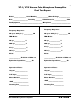
VT-1 / VT-2 Vacuum Tube Microphone Preamplifier Final Test Report Model _______________ Serial Number_______________Mains Voltage ______________ Date ___________________ Tested by ________ VU Calibrated to _______________ dBm Test Equipment ____________________________ Microphone ________________________ Channel b Channel A Frequency Response: Frequency Response: 20 cps to 20 kc/s +/- ___________ dB 20 cps to 20 kc/s +/- ___________ dB THD+Noise: THD+Noise: 20 cps ______________ % 20 cps ________
Table of Contents Final Test Report CE Certification Data Warranty .........................................................................................7 History of the VT-1 and VT-2 ..........................................................9 1. Specifications ..........................................................................13 2. Description...............................................................................15 3. Installation ......................................................
D.W. Fearn shall not be liable for technical or editorial errors or omissions in this manual, nor for incidental or consequential damages resulting from the use of this material. This instruction manual contains information protected by copyright. No part of this manual may be photocopied or reproduced in any form without prior written consent from D.W. Fearn. Copyright ©1995-2004 D.W. Fearn & Associates D.W.
Limited 5-Year Warranty During the warranty period, D.W. Fearn will, at no additional charge, repair or replace defective parts with new parts. This warranty does not extend to any VT-1 or VT-2 that has been damaged or rendered defective as a result of accident, misuse, or abuse; by the use of parts not manufactured or supplied by D.W. Fearn; or by unauthorized modification of the VT-1 or VT-2. Vacuum tubes are excepted from the 5-year warranty, but are warranted for 90 days from date of purchase.
History of the VT-1 and VT-2 Vacuum Tube Microphone Preamplifiers ONE DAY IN 1991 I was going through some old masters in a closet at home and came across a reel from 1968. It was one of the first studio recordings I ever made. I pulled the tape box off the shelf and thought about those days. Although I suspected that the recording might be a bit crude, I remembered that the music was pretty good, so I made a cassette to listen to in the car.
Over the years much has changed in the world of electronic components. Were the necessary parts still available? I found out that they were (though not necessarily cheap) and, in many cases, they were vastly better than the components available back in the age of vacuum tubes. Carbon resistors could be replaced with quieter metal film types. Sonically superior polystyrene and polypropylene capacitors were preferable to the old paper types. The power supplies could be solid state — and easily regulated.
is gross distortion — the output becomes a square wave. Square waves are not found in sounds that we consider musical, so our ears’ response to them is negative. When a tube circuit distorts, the primary distortion product is even order harmonics. It so happens that musical instruments also produce primarily even harmonics. By definition, that’s what makes them “musical.” So you could say that tube circuits can add a musical component to recorded sound.
The VT-2 was developed in 1995 in answer to requests from a number of our customers for a two-channel version of the preamp. The VT-2 occupies the same amount of rack space, but is four inches deeper than the VT-1. D.W.
1. S P E C I F I C AT I O N S Input 150 ohms Input Load Impedance 1.5k ohms Minimum Input Level -65 dBm nominal Maximum Input Level @ 20 cps Gain Frequency Response -30 dBm without pad -5 dBm with 20 dB pad 53 dB minimum ± 0.2 dB 20 cps to 20 kc ± 0.5 dB 11 cps to 28 kc -3 dB @ 0.5 cps & 50 kc THD + Noise <0.25% 20 cps to 20 kc Intermodulation Distortion SMPTE: <0.
2. DESCRIPTION The Model VT-1 and VT-2 Vacuum Tube Microphone Preamplifiers are designed to provide recording professionals with a sonically superior input device. (Unless there is a specific reason to address a difference between the VT-1 and VT-2 preamplifiers, the device will be referred to as the “VT-2.”) It is typically used in sound recording studios for recording individual tracks. A quality microphone is connected to a VT-2 input, and the VT-2 provides a line-level output.
3. I N S TA L L AT I O N The VT-2 is carefully packed for shipment and it should survive all but the most brutal handling. If there is any damage, keep the shipping material for use during any possible claim for damage with the shipper. Included in the box: 1) The VT-2 Microphone Preamplifier 2) Line cord 3) This instruction manual Mounting The VT-2 is designed for installation in a standard 19 inch rack. It requires 5.
if necessary. (Call the factory for detailed instructions). The ground pin of the power cord is internally connected to the chassis. This configuration is standard in professional equipment and is required by most electrical codes. A grounding screw is provided on the back panel for installations that use separate chassis grounding. If ground loop hum is detected, a careful check of the studio grounding scheme is needed. The VT-2 is less susceptible to grounding problems than many studio devices.
All connectors are wired according to AES standard: pin 1 is ground (shield), pin 2 is “high” or “+,” and pin 3 is “low” or “-.” A positive voltage on pin 2 of the input will result in a positive voltage on pin 2 of the output (with the Phase Reverse switch set to Normal). Grounding and Shields A full discussion of proper studio wiring schemes is beyond the scope of this manual, but, in general, the Input mating XLR connector must have the cable shield connected to pin 1.
D.W.
4. O P E R AT I O N Input Since the input cable will be carrying very low level audio, it is important that a well-shielded cable is used. There should be no additional connectors, patch jacks, switches, etc. between the microphone and the VT-2 input. This can be achieved with a dedicated line from an XLR connector in the studio to each VT-2 in the control room.
The VT-2 can feed balanced or unbalanced inputs with no need for any modification in output wiring. Either pin 2 or 3 can be grounded, although pin 2 is normally used as the ”hot” and pin 3 grounded in unbalanced configurations. CONTROLS (see Figure 2.) +48 volt phantom power on/off switch. Supplies 48 volts for phantom powered condenser microphones. Switch the 48 volts off for dynamic and ribbon microphones, or condenser microphones with their own power supplies (e.g. vacuum tube condensers).
Input “-20” position. In the “-20” position, a pad is inserted between the input connector and the input transformer. This position would be used when the level is too high for the “0” position. On condenser microphones that have a switchable pad, it will usually be necessary to use a -10 or -20 dB pad in the mic when recording very high sound levels to prevent overload of the microphone electronics.
The phantom powering circuit used in the VT-2 is suitable for use with all Neumann microphones, AKG 12 and 48 volt microphones, B&K phantom powered mics, all Schoeps mics, Shure SM81 and 85 mics, Crown PZM mics, and virtually all other phantom powered mics that require any voltage between 12 and 48. When turned off, the phantom-power resistors are completely disconnected from the circuit in the VT-2.
cate 0 on the meter. This is the standard “0 VU” level for all professional audio recording equipment built since the early 1970s. “0 VU” on the VT-2 should result in “0 VU” on a properly aligned recorder. (This reference level can be changed; see the Maintenance Section.) This is a true VU meter, and conforms to ASA Standard C16.5-1954. In some applications, or while testing the VT-2, the output level may be considerably higher than 0 VU.
The controls should be set as follows. The numbers refer to Figure 2 on page 21. • Power (8). . . . . . . . . . . . . . . . . . . . . . On • Input (2). . . . . . . . . . . . . . . . . . . . . . . 0 • Attenuation (3) . . . . . . . . . . . . . . . . . mid-point • Phase (4) . . . . . . . . . . . . . . . . . . . . . . Normal • Meter (5) . . . . . . . . . . . . . . . . . . . . . . On • +48 (1) . . . . . . . . . . . . . . . . . . . . . . . . as required for mic If necessary, use the Phase reverse switch.
4. The output of the VT-2 should be fed directly to the recorder through the shortest practical length of quality cable. Avoid additional cables, connectors, junction boxes, punch blocks, or patch jacks. Use gold contact connectors if possible. Do not go through the mixing console unless you absolutely need its features for the track you are cutting. 5. In general, for superior sound, we recommend recording directly to the recorder with no processing (compression, equalization, gating, etc).
D.W.
5. T H E O RY O F O P E R AT I O N Input section Microphone level (150 ohm source impedance, balanced, -50 dBm nominal) audio enters through the XLR-3 female INPUT connector to the three-position Input selector switch. In the 0 position, the input is connected directly to the input transformer. The load imposed on the microphone is 1500 ohms, but varies slightly with frequency but is never lower than 1100 ohms. In the -20 position, the input passes through a balanced 20 dB pad.
Input transformer The input transformer is custom-made for D.W. Fearn by Jensen Transformers, Inc. and represents the state of the art in transformer design. It exhibits extremely flat frequency response, low phase shift, excellent square wave response, low distortion, and high noise immunity. The secondary of is connected directly to the grid of the first amplifier stage. Figure 4.
Third Stage The arm of the Attenuation potentiometer feeds the grid of the third stage (a 6072A), which also operates Class A with a gain of approximately 30. This stage is capacitively-coupled to the grid of the output stage through a polystyrene capacitor. Output Stage The output stage operates as a cathode follower, presenting a comparitively low output impedance (approximately 800 ohms).
Filament Supply The power transformer output is rectified by a bridge rectifier and filtered before being regulated to 12.0 volts by a three-terminal regulator. The negative output of this supply is grounded. Although the filaments are rated for 12.6 volts, utilization of 12.0 volts has no effect on the operation of the VT-1/VT-2. Meter Amplifier Supply A negative version of the filament supply provides regulated -12 volts for the IC operational amplifiers in the meter amplifier circuit.
6. MAINTENANCE The VT-2 is built with only the highest quality parts and will prove to be extremely reliable. Vacuum tubes and electrolytic capacitors, however, have a finite useful life and must be replaced eventually. Top Cover Removal Removing the top cover allows access to the vacuum tubes, the VU meter calibration, and to the rotary switches. 6-32 allen-head bolts must be removed (phillips-head machine screws are used on the VT-1).
and grade them according to noise, microphonic response, distortion, and other characteristics. A low-noise tube from us will meet the original VT-2 specifications. The base pins of vacuum tubes supplied by D.W. Fearn have been chemically treated for low contact resistance and oxidation prevention. When handling these tubes, care should be taken to avoid removing or contaminating the treatment. Use a lint-free cloth or paper towel to avoid direct contact between any part of the tube and your fingers.
VU Meter Calibration The meter amplifier circuit is stable and re-adjustment of the meter calibration is not normally required. If the output reference level needs to be changed, here is the procedure: 1. Remove the VT-2 top cover (see above). 2. Terminate the output in the same impedance as the VT-2 will normally be feeding. This will almost always be a high-impedance bridging termination of 20k ohms or more. 3. Apply AC power. Allow at least a fifteen minute warm-up.
Warranty Repair If the VT-2 should develop a problem during the five-year warranty period, call the factory for return shipping instructions. We will repair and return your VT-2 quickly. Note that the warranty does not cover vacuum tubes, which must be periodically replaced. D.W.
LP -1 Line Pad Accessory The LP-1 Line Pad is an accessory for the VT-1 and VT-2 Vacuum Tube Microphone Preamplifiers that allows the preamp to accommodate a line-level signal of approximately +4 dBm. This is used when it is necessary for the VT-2 to process a line-level signal, such as in final processing of a mix. Note that the LP-1 is not designed to be used as a “direct box.” For most musical instruments, the level and impedance are not correct for use with the LP-1.