
Operating instructions


D.W. FEARN
VT-1 & VT-2 Microphone Preamplifers
24
The VT-2 can feed balanced or unbalanced inputs with no need for any modification in out-
put wiring. Eit
her pin 2 or 3 can be gr
ounded, alt
hough pin 2 is normally used as the ”hot”
and pin 3 grounded in unbalanced configurations.
C
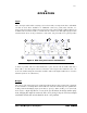
ONTROLS (see Figure 2.)
+48 volt phantom power on/off switch. Supplies 48 volts for phantom powered condenser
microphones. Switch the 48 volts off for dynamic and ribbon microphones, or condenser
micr
ophones with their own power supplies (e.g. vacuum tube condensers).
Attenuation contr
ol. Adjusts the output level.
Phase switch
.
Usually in the Normal position except when it is necessary to reverse
the polarity of a microphone.
Meter
switch.
T
urns on or off the VU meter. Normally ‘on’ except during some test
procedures or when purposely over
-driving the
VT-2.
VU meter
.
Monitors the output level of the
VT
-2.
Pilot lamp
. Illuminates when AC power is applied and the Power switch is on.
Power
switch. Controls primary AC power to the VT-2.
P
ower switch and indicator
Primary power is applied to the VT-2 circuits when the Power switch (8) is in the up position.
The amber pilot lamp (7) indicates that the unit is on. It takes about twenty seconds for the
preamp to start working, but it is suggested that you turn on the power at least five minutes
prior to use. The tubes ar
e often noisy until all the internal elements reach a stable operat-
ing tem
perature.
Input “0” position.
In t
he “0” position, microphone audio is connected directly to the input transformer. This
provides the proper amplification for most condenser microphones, and will be used in many
micing situations. In the “0” position, the VT-2 can accept up to about a -30 dBm input sig-
nal at 20 cps wit
h full g
ain (53 dB) without an increase in distortion.