
Operating instructions


D.W. FEARN
VT-1 &
VT-2 Microphone Preamplifers
31
5.
THEOR
Y OF OPER
A
TION
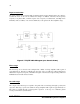
Input section
Micr
ophone level (150 ohm source impedance, balanced, -50 dBm nominal) audio enters
t
hrough the XLR-3 female INPUT connector to the three-position Input selector switch. In
the 0 position, the input is connected directly to the input transformer. The load imposed on
t
he microphone is 1500 ohms, but varies slightly with frequency but is never lower than 1100
ohms.
In the -20 position, the input passes through a balanced 20 dB pad. This pad is designed to
maint
ain appr
oximately the same load on the microphone as the input transformer.
All switching is t
hrough sealed gold-contact instrumentation relays with bifurcated contacts.
Phantom po
w
ering
+5
1 fr
om the phantom power supply is switched on and off by the front panel +48 switch. A
resistor drops the voltage as required depending on the current being drawn by the con-
denser micr
ophone electronics. This makes the phantom power supply universal for most 12
and 48 volt condenser microphones. The phantom powering resistors are precision matched
to 0.10% or better. They provide exactly equal voltage to pins 2 and 3 respectively of the input
connector
. The switching is t
hrough sealed gold-contact instrumentation relays with bifur-
cated contacts. In the “Off” position, the phantom power resistors are completely discon-
nected fr
om the microphone connector.
Phase re
versal switch
In the Normal position, input/output phase (polarity) is maintained (which must be inverted
due to t
he design of the circuit). The balanced output is polarity reversed in the Reverse posi-
tion. Switching is accom
plished with a sealed, gold-contact instrumentation relay with bifur-
cated contacts.