
Manual

4
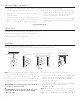
Screen Adjustment For Screens Without A Built-In Low Voltage Control
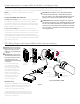
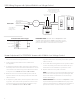
120V Wiring Diagram with Optional Built-In Video Projector Interface
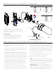
Surface travel is stopped automatically in the fully opened and closed positions by limit switches that are properly adjusted at Da-Lite.
Should it be necessary to adjust for more or less picture drop (viewing area), proceed in the following manner:
NOTE: Use a screwdriver or 5/32" Allen wrench to make
adjustments.
SETTING THE DOWN LIMIT POSITION
To Reduce Screen Drop: Turn the white limit switch screw (Figure
3) clockwise to decrease the amount of screen drop. Run the
screen down to test the stop position. If the screen drops too far,
raise the screen about one foot and adjust the limit switch again.
Repeat until the desired position is set.
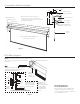
To Increase Screen Drop: Turn the white limit switch screw
counterclockwise to increase the amount of screen drop. Run the
screen down to test the stop position. If the screen does not drop
enough, raise the screen about one foot and adjust the limit
switch again. Repeat until the desired position is set. Do not adjust
for more drop than what was ordered. At least 11/2 wraps of fabric
must remain on the roller.
CAUTION: Do not adjust for more drop than what was
ordered. At least 11/2 wraps of fabric must remain on
the roller. This screen comes standard with 0" or 2" black
at the top. See the speciication data sheet for details.
ATTENTION! N'efectuez pas de réglage pour obtenir un
déroulement supérieur à celui commandé. Au moins 1 à 1/2
tour de toile doit être maintenu sur le cylindre. Cet écran
est doté de série d'une bande noire supérieure de 0 cm (0
po) ou 5 cm (2 po). Consultez la iche technique pour plus
de renseignements.
CAUTION: The projector must be
turned of before connecting the
trigger wires to the projector.
Failure to do so may damage the
controller.
ATTENTION: Le projecteur doit
être éteint avant de brancher les
ils de déclenchement à celui-ci.
Tout manquement à cette
instruction pourrait endommager
le contrôleur.
Use 2-conductor 2024 gauge
wire to extend the low voltage
connection from the projector’s
5 or 12-volt screen trigger output
to the length required to reach
the VPI. When extending the low
voltage connection from the
projector’s screen trigger output
polarity does not matter. The
red and black wires from the
VPI are interchangeable.
IMPORTANT NOTE:
The wall switch is REQUIRED to make any limit switch
adjustments, EVEN if a third party control system is used.
Therefore, it is advised to wire the switch or provide a
3-conductor connection that is accessible.
3-conductor 2024 gauge wire can be used in place of the
supplied RJ14 cable to connect the wall switch. Connect the
BUS terminals on the wall switch to the corresponding BUS
terminals on the splitter board.
⁄ Volt Screen
Trigger On Projector
Ground–Must Be Connected
To Building Ground
UP
STOP
DOWN
Power Input 120Vac / 60Hz
Green (Ground)
Black (Hot)
White (Common)
Power
Wire
Data Cable
RJ45 Jack
RJ45 Receptacle
RJ22 Output
RJ22 Jack
RJ22
Inputs
RJ22
Jack
LED
Up
Limit
Tactile
Button
Down
Limit
Tactile
Button
Front Of
Wall Switch
Back Of
Wall Switch
Black
Red
VPI Trigger Module
Dry Contacts
Up
Down
Common
Bus
5V
BUS
BUS
COM
5V
BUS
Figure 4