
Manual

6
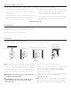
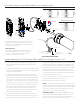
Screen Adjustment For 220V/240V Screens with A Built-In Low Voltage Control
1. Remove the cover plate from the 3-button wall switch and
remove the switch from the junction box.
2. Locate small 3-position switch on back of wall switch.
(See Figure 6)
3. To adjust the down limit switch, slide the 3-position switch to
the down position. Press and hold the down button to run the
screen down to the desired stop position. Release the button
to stop the screen. DO NOT PUSH THE STOP BUTTON.
4. When the screen is in the desired down position, slide the
3-position switch to the of (center) position. The down limit
switch is now set.
5. To adjust the up limit switch, slide the 3-position switch to the
up position. Press and hold the up button to run the screen
up to the desired stop position. Release the button to stop
the screen. DO NOT PUSH THE STOP BUTTON.
6. When the screen is in the desired up position, slide the
3-position switch to the of (center) position. The up limit
switch is now set.
7. To test limit switch setting, make sure the 3-position switch
is in the of (center) position. Press and release the up or
down button on the wall switch to operate the screen.
8. Replace switch and cover plate on the wall.
NOTE: If stop button is pressed, the wall switch will reverse
direction. To correct this, press the stop button again. This
will reset the switch. You will have to re-set both the up
and the down settings.
IMPORTANT NOTE: The wall switch is REQUIRED to make
any limit switch adjustments, EVEN if a third party control
system is used. Therefore, it is advised to wire the switch or
provide a 4-conductor connection that is accessible.
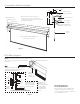
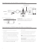
240V Wiring Diagram with Optional Built-In Low Voltage Control
Figure 6
Low-Voltage Wall Switch
Optional IR and RF
Remote Control
Splitter
Motor
Ground to Case
240VAC 50Hz
Up
Stop
Down
Ground–Must be
Connected to
Building Ground
Green
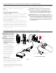
Front Back
UP DN
GND +5V
3Position
Switch
RJ9
UP
+5V
COM
DN
IMPORTANT NOTE: The wall switch is REQUIRED to make
any limit switch adjustments, EVEN if a third party control
system is used. Therefore, it is advised to wire the switch or
provide a 4-conductor connection that is accessible.
Connect Supplied RJ9 Cable
to Splitter and Switch, or use
4 Cable Conductor to Connect
to Screw Terminals.
ILT RJ9 Pin-Outs (Tab Is Facing Up)
Ground Common
IR or Up
+5V
Data or Down
Red
Green
White
Black
Green
Brown (Hot)
Blue (Common)
RJ9
RJ9
Dry Contacts