
Owner's Manual


CAUTION: THE PROJECTOR MUST BE TURNED OFF BEFORE CONNECTING THE TRIGGER WIRES TO THE PROJECTOR. FAILURE
TO DO SO MAY DAMAGE THE CONTROLLER.
1. Use 2-conductor 20-24 gauge wire to extend the low voltage connection from the projector’s 5 or 12-volt screen
trigger output to the length required to reach the VPI. When extending the low voltage connection from the
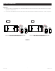
projector’s screen trigger output, be sure to maintain the proper polarity. the red wire from the VPI is the “signal”
and the black wire from the VPI is the “ground”.
2. Connect the wires from the VPI that are labeled “Low Voltage Connection” to the end of the extended screen
trigger wires above. See Figure 1.
CAUTION: NEVER APPLY VOLTAGE TO THE PROJECTOR’S SCREEN TRIGGER WIRES OR THE VPI AND/OR PROJECTOR WILL BE
DAMAGED.
VIDEO PROJECTOR INTERFACE INSTALLATION
1
The Video Projector Interface (VPI) housing is divided into three compartments. The compartment labeled “Low Voltage
Connections” is where you will connect the VPI to the projector’s output and wall switch wire connections. The
compartment labeled “AC Power Connections” is where the main power and motor wire connections are made. Access
is not required to the center compartment.
WARNING: TO PREVENT ELECTRICAL SHOCK OR DAMAGE TO THE VIDEO PROJECTOR INTERFACE (VPI), DO NOT APPLY
POWER TO THE VPI UNTIL ALL CONNECTIONS ARE COMPLETE. MAKE SURE POWER IS TURNED OFF ON ALL CIRCUITS
BEFORE MAKING CONNECTIONS.
CAUTION: ANY ITEM BEING CONNECTED TO THE VPI CANNOT BE ENERGIZED.
▲
!
LOW VOLTAGE CONNECTION
RED
BLACK
RED
BLACK
5/12 VOLT SCREEN
TRIGGER ON
PROJECTOR
5/12 VOLT SCREEN
TRIGGER ON
PROJECTOR
RECOMMENDED WIRE SIZE:
20-24 AWG RECOMMENDED WIRE SIZE: 20-24 AWG
FIGURE 1
120V 240V
▲
!
▲
!
▲
!