INSTRUCTION BOOK FOR Curved Multi Format Imager
Important Safety Instructions Pre-Installation When using your video equipment, basic safety precautions should always be followed, including the following: The screen will arrive in three separate cardboard boxes. One box will be very long and will house the 4.75” x 8.00” top and bottom main frame parts, the 1.50” x 1.50” frame parts, hardware and wall switch. The second cardboard box will house the 4.75” x 8.00” side main frame parts.
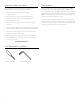
Da-Snap Frame Assembly 1. 4. Unroll the screen on a clean surface. Do not use newspaper. Place screen surface over the frame, and while holding the frame with one hand, snap the screen surface onto the frame with the other hand while maintaining a steady pull on the surface. Start with the four corners. Inside each box the frame pieces will be individually paper wrapped and taped. Remove all paper from pieces. Do not use a utility knife to remove paper from pieces. 2. Unpack the 1.50” x 1.
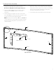
Curved Multi Format Imager Assembly 1. will slide into the frame channel. When sliding the bracket into the top frame assembly, guide the slat roller carriage into the top aluminum guide track as shown in Figure 3. Lay frame pieces out on the floor or table as shown in Figure 2. The bottom frame assembly has the junction box attached to it. The side frame assemblies have the rollers and motors attached to them. 2.
Curved Multi Format Imager Assembly 7. 4. Assemble bottom end of left frame assembly to end of bottom frame assembly. The large L-bracket will slide into the aluminum extrusion while the small L-bracket will slide into the frame channel. When sliding the bracket into the bottom frame assembly, guide the slat roller carriage into the bottom aluminum guide track. See Figure 5. 5.
Curved Multi Format Imager Assembly 9. Route the two cable assemblies around motor bracket and plug the 3 wire male connector into the 3 wire female connector on the motor bracket. The motor will have a gray data cable with and RJ-45 connector and RJ-45 coupler on the end coming out of the head of the motor. Plug the connector of the cable assembly into the RJ-coupler. Tuck the RJ-45 coupler underneath motor bracket securely to prevent entanglement as shown in Figure 8. 10.
Curved Multi Format Imager Assembly Clip Wire Tension Cable To Eyebolt Slat Bar Safety Cable Passes Through Middle of Spring Clip Safety Cable To Middle Eyebolt Insert Wire Between Brackets, Lower And Wrap Around Pulley Pinch Guard Figure 10 Black Knob (4 or 6 For Top Brackets Top Brackets (4 or 6) Black Knobs (4 or 6 For Bottom Brackets Junction Box Cover Bottom Brackets (4 or 6) Slide This End of Da-Snap Frame First, Under Bottom Brackets Figure 11 7
Curved Multi Format Imager Installation – Wall Mount 1. The screen is shipped with one wall hanger board. Two small brackets are included to hold the frame securely to wall at the bottom. 2. The wall hanger board must be mounted into at least four wall studs; it must be horizontally leveled. 3. Secure wall hanger board to wall studs at the desire height. Drill holes and attach wall hanger board into wall. You will need about 3” clearance above the top surface of the board.
Multi Format Imager Wiring Diagram 1. To connect power to unit locate junction box cover on bottom frame assembly. There will be two black screws holding the wiring box cover on as shown in Figure 13. 2. Install electrical connections. Make sure to review the wiring diagram for proper hook up as shown in Figure 14. NOTE: Must be installed in accordance with the requirements of the Local Building Codes, the Canadian Electrical Code (CEC), CAN/CSA C22.1 and the National Electric Code (NEC), NFPA 70.
Multi Format Imager Wiring Diagram Connect IR eye to splitter for screen operation. IR eye shall be plugged into a QEYE port on the primary splitter as shown in Figure 15. NOTES: 1.) 6P6C = 6 Pins 6 Conductor Wire 2.
Multi Format Imager Intermediate Stop Adjustment 1. To adjust intermediate stopping positions make sure both masks are completely retracted into the frame. Press the left mask ">" button. The mask will start to move outward. Press the stop button at the position you want it set to. If you go too far outward press the left mask "<" button and the mask will retract back into the case. 3. Once both masks are at the desired stopping position.
Multi Format Imager Limit Travel Adjustment (Continued) 6. Locate the two tactile buttons on the back of the switch. They are square silver with black round buttons as shown in Figure 18. 7. To adjust how far the mask travels outward towards the middle of masking screen, press and hold the down tactile button until the LED on back of switch turns solid red. This will put the motor in limit set mode. Turn the wall switch over and use the down button on front of switch.
Troubleshooting Visit www.da-lite.com to find installation and troubleshooting videos and tutorials. You will also find a link to Live Chat for interactive support and you can contact us by email at Symptom asking System will not operate. M Motor does not hum. info@da-lite.com or by phone at (800) 622-3737 or (574) 267-8101 with any troubleshooting questions. Cause Solution Incorrect line voltage. Verify 115-125V (or 220-240V). If insufficient voltage, rewire incoming electric line. Blown fuse.
LIMITED ONE YEAR WARRANTY ON DA-LITE PRESENTATION PRODUCTS Milestone AV Technologies LLC warrants certain Da-Lite branded products to the original purchaser only, to be free from defects in materials and workmanship for a period of one (1) year from the date of purchase by the original purchaser; provided they are properly operated according to Da-Lite's instructions and are not damaged due to improper handling or treatment after shipment from the factory.