The Da-Lite Difference. Instruction Book for Motorized Scenic Roller Screen DA-LITE SCREEN COMPANY, INC. 3100 North Detroit Street Post Office Box 137 Warsaw, Indiana 46581-0137 Phone: 574-267-8101 800-622-3737 Fax: 574-267-7804 www.da-lite.com e-mail: info@da-lite.
IMPORTANT SAFETY INSTRUCTIONS When using your video equipment, basic safety precautions should always be followed, including the following: 1. Read and understand all instructions before using. 2. Position the cord so that it will not be tripped over, pulled, or contact hot surfaces. 3. If an extension cord is necessary, a cord with a current rating at least equal to that of the appliance should be used. Cords rated for less amperage than the appliance may overheat. 4.
INSTALLATION Before proceeding with the installation please read the installation and operating instructions thoroughly. Make sure to recheck measurements of screen and hanger locations before installation. Area must be clear for screen to operate. With all lid sections removed from shipping container, remove the screws holding the frame to the shipping container (2 per cross brace). The screen can now be carefully lifted out of the container.
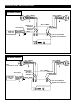
MOTORIZED SCENIC ROLLER INSTALLATION 120V WIRING DIAGRAM WHITE - (COMMON) RED - (UP) BLACK - (DOWN) GREEN - (GROUND) WHITE - (COMMON) BROWN - OUT OF CONTROLLER RED - OUT OF CONTROLLER SAFETY SWITCH WHITE - (COMMON) BLACK - (HOT) GREEN - (GROUND) BLACK POWER INPUT 120VAC / 60HZ WHITE - (COMMON) RED - (UP) BLACK - (DOWN) GREEN - (GROUND) RED - (UP) BLACK - (DOWN) WHITE RED - OUT OF CONTROLLER BROWN - OUT OF CONTROLLER 240V WIRING DIAGRAM BLUE - (COMMON) BLACK - (UP) BROWN - (DOWN) GREEN/YELLOW - (GR
MOTORIZED SCENIC ROLLER INSTALLATION 120V / 240V WALL SWITCH WIRING DIAGRAM FRONT OF WALL SWITCH BACK OF WALL SWITCH UP STOP DOWN OPTIONAL RF REMOTE CONNECTION RED - (UP) BLACK - (DOWN) WHITE - (COMMON) NOT USED NOTE: 20-24AWG WIRE RECOMMENDED FOR CONNECTING WALL SWITCH TO SYCHRONIZATION CONTROLLER IMPORTANT! The wall switch terminal block can be connected inside the wiring compartment. The controller does not need to be removed from the junction box unless an RF remote is being connected.
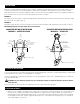
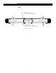
LIMIT SWITCH ADJUSTMENT The stop positions of the screen are preset at the factory. If adjustments are necessary, the limit switch screws located at the end of each motor can adjust the stop positions. Use a 5/32" hex key or a flat screwdriver. Adjustments should be made in small increments by turning the adjustment screws a half turn at a time. Refer to figure 3. SETTING THE “DOWN” LIMIT POSITION.
LIMIT SWITCH ADJUSTMENT FIG.
LIMITED ONE YEAR WARRANTY ON DA-LITE PRESENTATION PRODUCTS Da-Lite Screen Company, Inc. warrants its products to the original purchaser only, to be free from defects in materials and workmanship for a period of one (1) year from the date of purchase by the original purchaser provided they are properly operated according to Da-Lite’s instructions and are not damaged due to improper handling or treatment after shipment from the factory.