
Operating instructions


4
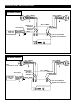
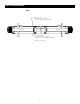
MOTORIZED SCENIC ROLLER INSTALLATION
120V / 240V WALL SWITCH
WIRING DIAGRAM
WHITE - (COMMON)
BLACK - (DOWN)
RED - (UP)
FRONT
OF
WALL
SWITCH
BACK
OF
WALL
SWITCH
UP
STOP
DOWN
OPTIONAL RF REMOTE
CONNECTION
NOT USED
NOTE: 20-24AWG WIRE RECOMMENDED
FOR CONNECTING WALL SWITCH TO
SYCHRONIZATION CONTROLLER
IMPORTANT! The wall switch terminal block can be connected inside the wiring compartment. The controller does not need to be
removed from the junction box unless an RF remote is being connected. Use caution when removing the controller from the box as it
is easily damaged.