The POWER In PRESENTATION PRODUCTS Instruction Book for PRO IMAGER DA-LITE SCREEN COMPANY, INC. 3100 North Detroit Street Post Office Box 137 Warsaw, Indiana 46581-0137 Phone: 574-267-8101 800-622-3737 Fax: 574-267-7804 www.da-lite.com e-mail: info@da-lite.
IMPORTANT SAFETY INSTRUCTIONS When using your video equipment, basic safety precautions should always be followed, including the following: 1. Read and understand all instructions before using. 2. Position the cord so that it will not be tripped over, pulled, or contact hot surfaces. 3. If an extension cord is necessary, a cord with a current rating at least equal to that of the appliance should be used. Cords rated for less amperage than the appliance may overheat. 4.
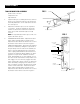
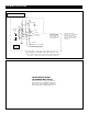
FRAME ASSEMBLY FIG. 1 TOOLS REQUIRED FOR ASSEMBLY SLAT BAR 5/16" socket or wrench Carpenters level Tape Measure 1. 2. Unpack frame pieces and lay them face down on the floor. The top frame has the roller and motor assembly attached to it. The side frames are the two short pieces. CHANNEL Attach the side frame pieces to the top frame. See figure 1. Insert the slat bar into the small channel located on the side frame. Fasten the frame pieces with four #10 x 3/4" hex head screws.
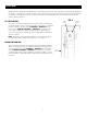
INSTALLATION (Continued) 1. To install the Pro Imager over a Da-Lite Perm-Wall screen you will need to place the supplied wooden spacers between the screen and the wall. Da-Snap and Imager screens do not require any spacers. 2. Refer to figure 3 for hanger bracket location. Dimension A will vary depending on the type of screen you have. Dimension A is measured from the top of the screen frame to the top of the hanger bracket. Screen type Perm-Wall Imager Da-Snap Dimension A 3-7/8" 3-7/8" 4-3/8" FIG.
PRO IMAGER INSTALLATION 120V WIRING DIAGRAM COMMON WHITE UP BLACK DOWN RED TO MOTOR RED ROCKER SWITCH UP WHITE BLACK OPERATING SWITCH, SWITCH BOX, AND PLATE FURNISHED WITH SCREEN. (SPDT WITH CENTER OFF) BLACK WITH YELLOW OFF DOWN AC COMMON SIDE VIEW OF SWITCH AND BOX AC HOT 120V. 60-HZ 2.5 MAX. AMP THIS SWITCH CANNOT BE USED WITH LVC. Note: A single switch cannot be used to operate more than one screen. Contact the factory for further information.
ADJUSTMENT Masking travel is stopped automatically in the up and down positions by limit switches that are properly adjusted at the factory. Should it be necessary to adjust the stop positions, proceed in the following manner using a small flat screwdriver or a 5/32" allen wrench. Access to the switches is provided by holes on the top left side of the Pro Imager. Refer to figure 4. FIG.
TROUBLESHOOTING SYMPTOM 1. Screen will not operate or will not go “down”. Motor does not hum. CAUSE SOLUTION (a) Blown facility fuse. (a) Replace facility fuse. (b) Tripped facility circuit breaker. (b) Reset circuit breaker. (c) No power to operating switch or junction. (c) Check above. Tighten all loose wire connections. Recheck wiring. See installation instructions. “Down” Position Check for power across black and white leads. Power at junction box. Motor hums. 2. Screen will not move “up”.
Printed in U.S.A. 82391 Rev.