
Installation instructions


5
ADJUSTMENT
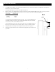
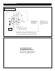
Masking travel is stopped automatically in the up and down positions by limit switches that are properly adjusted at
the factory. Should it be necessary to adjust the stop positions, proceed in the following manner using a small flat
screwdriver or a 5/32" allen wrench. Access to the switches is provided by holes on the top left side of the Pro
I
mager. Refer to figure 4.
UP LIMIT CONTROL
The up limit controls the stop position when the mask is traveling up,
or unmasking the screen. Set the Pro Imager to the down, or masked
position. Turn the up limit control CLOCKWISE to DECREASE the up
travel. Turn it COUNTER-CLOCKWISE to INCREASE the up travel. Turn
the control a quarter turn at a time and then run the Pro Imager to
check the stop position. Repeat the above steps until the desired po-
sition is reached.
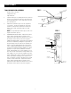
NOTE: The bottom of the slat bar should be no more than 1/8" above
the edge of the frame while in the up position. See figure 2.
DOWN LIMIT CONTROL
The down limit controls the stop position when the mask is traveling
down, or masking the screen. Set the Pro Imager in the up position.
Turn the down limit control CLOCKWISE to DECREASE the down travel.
Turn it COUNTER-CLOCKWISE to INCREASE the down travel. Turn the
control a quarter turn at a time and then run the Pro Imager to check
the stop position. Repeat the above steps until the desired position is
reached.
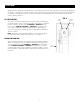
U
P LIMIT
CONTROL
V
IEWING
SURFACE
DOWN LIMIT
CONTROL
FIG. 4