Installation Instructions Discover y ® Gas Cooktop Models DYCT304G, DYCT365G Part No. 108861 Rev.
Table of Contents Important Safety Instructions.......................................1 Verifying the Package Contents....................................8 Important Information About Safety Instructions...........1 Installing the Cooktop....................................................8 General Safety Precautions..........................................2 Connecting the Gas Line..............................................8 Electrical Requirements................................................
Important Safety Instructions Important Information About Safety Instructions IMPORTANT: If you smell gas: • • Do not use or light any appliance. • Do not touch any electrical switch or use any electrical devices, including the telephone, in your building. • From a neighbor’s phone, immediately call the gas supplier. Follow the gas supplier’s instructions. • If you cannot contact the gas supplier, call the fire department.
Important Safety Instructions General Safety Precautions To reduce the risk of fire, electric shock, or serious injury or death when using your appliance, follow basic safety precautions, including the following: WARNING • Read the accompanying use and care manual completely before operating this appliance. • Keep packaging materials away from children. Plastic sheets and bags can cause suffocation. • If you receive a damaged product, immediately contact your dealer or builder.
Important Safety Instructions Electrical Requirements Gas Supply Requirements WARNING To prevent an electric shock hazard, the power supply must meet the specifications stated below. It is the owner’s responsibility to make sure that the electrical service meets electrical requirements and that the electrical outlet has been properly installed by a licensed electrician. • • The cooktop is supplied with a factory installed, 40-inch, three-prong, grounding electrical cord.
Installation Specifications WARNING Observe all governing codes and ordinances during planning and installation. Contact your local building department for further information. Product Dimensions All tolerances: ±1/16” (±1.6 mm) unless otherwise noted. Model DYCT304G 30” (76.2 cm) Chassis height Bottom of spill tray to top of cooking surface 4” (10.2 cm) 2 1/8” (5.4 cm) 21” (53.3 cm) 19 1/2” * (49.5 cm) 27 1/2” * (69.
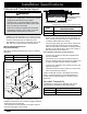
Installation Specifications Model DYCT365G 36” (76.2 cm) Chassis height 4” (10.2 cm) Bottom of spill tray to top of cooking surface 2 1/8” (5.4 cm) 33 5/8” * (85.4 cm) 21” (53.3 cm) 19 1/2” * (49.5 cm) * Including raised embosses on sides of chassis Front of cooktop Gas inlet Power cord in 2 1/4” (5.7 cm) 1” (2.5 cm) 1” (2.5 cm) DYCT365G Power Cord and Gas Inlet Location 1 3/8” (3.
Installation Specifications Cabinet and Countertop Layout WARNING • To reduce the risk of personal injury caused by reaching over a hot appliance, avoid locating cabinet storage space directly above the cooktop. • Failure to meet or exceed the maximum and minimum dimensions/clearances stated in these instructions may result in a fire hazard. • B Underneath Cabinet Dimensions All tolerances: +1/16” -0” unless otherwise noted.
Installation Specifications Cutout Dimensions All tolerances +1/16” -0” (+1.6 mm) unless otherwise noted. Countertop Cutout View Rear wall Vertical combustible surface 4 1/4" (10.8 cm) min. from mounting surface to combustibles below cooktop chassis F C E D F Countertop Cutout Dimensions Min. distance to combustible side wall above countertop (both sides) 1 7/8" min. (4.8 cm) Installation Type DYCT304G with no downdraft DYCT304G with ERV3015 or PRV30 DYCT304G with RV30 (C) Minimum (D) 2 7/8” (7.
Installation Instructions Verifying the Package Contents • Hold-down brackets (2) • Grates: DYCT304G (2), DYCT365G (3) • Burner sets: DYCT304G (4), DYCT365G (5) • Gas pressure regulator (1) • Stainless steel cleaner (1) (stainless steel models only) Connecting the Gas Line WARNING If any parts are missing, see the Replacement Parts List section on page 12 for Dacor Customer Service and ordering information.
Installation Instructions Assembling the Burners WARNING • Never attempt to operate the cooktop with any of the burner parts removed. • Do not attempt to adjust the burner air mixture settings. All adjustments are preset at the factory. 1. Remove the burner heads, burner rings, burner caps, and grates from their shipping packages. 2. Assemble the burners as shown below. When assembling the burner components, twist each piece back and forth until it drops completely into place.
Installation Instructions Verifying the Correct Setup WARNING • Make sure that power to the electrical outlet is turned off at the circuit breaker panel or fuse box and that the gas is turned off at the gas supply valve before proceeding. • The cooktop must be properly grounded at all times when electrical power is applied. Prior to operating the cooktop, read the accompanying Use and Care Manual carefully. 1. Make sure all the cooktop burner controls are in the OFF position. 2.
Installation Instructions Installation Checklist WARNING To ensure a safe and proper installation, the following checklist should be completed by the installer to ensure that no part of the installation has been overlooked. Proper installation is the responsibility of the homeowner. The importance of proper installation of your Dacor cooktop cannot be overemphasized.
Replacement Parts List Replacement Parts List Replacement parts can be obtained by contacting Dacor Customer Service. Model DYCT304G Dacor Customer Service Phone: (800) 793-0093 (U.S.A. and Canada) Monday — Friday 6:00 a.m. to 5:00 p.m.
Replacement Parts List Burner Parts Grate Feet Cap cover Cap cover (bottom view) Burner head Burner cap Line up this notch with the igniter Burner skirt Wide side down Igniter Burner head * Burner base Single Burner Assembly Cooktop Layout SimmerSear™ Burner Assembly Spill tray RR LR Burner control knob & Trim ring Burner Location LR Left Rear RR Right Rear CR Center Rear LF Left Front RF Right Front CF Center Front * Burner head on SimmerSear is attached to the spill tray.
Wiring Diagrams 120V, 60Hz. POWER SUPPLY VERIFY PROPER OPERATION AFTER SERVICING 14 WIRING DIAGRAM DYCT304G CAUTION: LABEL ALL WIRES PRIOR TO DISCONNECTION WHEN SERVICING CONTROLS. WIRING ERRORS CAN CAUSE IMPROPER AND DANGEROUS OPERATION.
Wiring Diagrams WIRING DIAGRAM DYCT365G 120V, 60Hz. POWER SUPPLY CAUTION: LABEL ALL WIRES PRIOR TO DISCONNECTION WHEN SERVICING CONTROLS. WIRING ERRORS CAN CAUSE IMPROPER AND DANGEROUS OPERATION.
Dacor ● 14425 Clark Avenue, City of Industry, CA 91745 ● Phone: (800) 793-0093 ● Fax: (626) 403-3130 ● www.dacor.