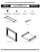
For Microwave Models: DMW2420S & DMW2420B INSTALLATION INSTRUCTIONS Trim Kits # ADMWTK271S & ADMWTK271B Parts Included with Kit (8) #10 x 1/2 Phillips head screws (PN 83022) (2) Flat head / Phillips head screws (PN 107578) (8) Fiber washers (PN 83555) (2) Rubber Bumpers (PN 72165) (2) Trim supports (2) Shims (1) Trim Assembly (1) Base assembly Part No. 108452 Rev.
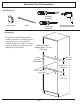
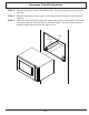
Microwave Trim Kit Instructions Tools Required Flat blade screwdriver Tape measure Pencil Phillips head screwdriver Drill with 3/32” drill bit (for drilling pilot holes) Introduction For proper fit, the cutout dimensions shown are required. The spacing above and below the cutout are critical for ventilation purposes. Failure to provide proper ventilation will result in possible Minimum interior damage to the microwave. cabinet depth: 20” min. (50.8 cm) 1” min. (2.5 cm) both sides 5/8” min. (1.
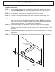
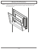
Microwave Trim Kit Instructions Installation Instructions STEP 1 Insert one of the trim supports into the bottom of the cutout as shown and center it, left to right. IMPORTANT: Use a measuring tape or ruler to center the piece in the cutout. If the trim support is not centered, the trim assembly will not fit properly. STEP 2 Using a pencil, mark 4 pilot hole locations in the front of the cabinet. STEP 3 Remove the trim support and drill 4 pilot holes in the places marked using a 3/32” drill bit.
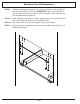
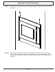
Microwave Trim Kit Instructions STEP 8 Hold the remaining trim support in the mounting position on the top edge of the cutout and center it left to right. IMPORTANT: Use a measuring tape or ruler to center the piece in the cutout. If the trim support is not centered, the trim assembly will not fit properly. STEP 9 While holding the trim support in place, using a pencil, mark 4 pilot hole locations in the underside of the top of the cabinet cutout.
Microwave Trim Kit Instructions STEP 12 Place the microwave close to the cabinet cutout. Connect the power cord to the electrical outlet. STEP 13 Insert the microwave into the cutout. Put the legs on the microwave on top of the base supports. STEP 14 Center the microwave left to right in the cutout using a ruler or tape measure. Push the microwave back until it hits the stops on the base support. The front of the microwave needs to extend from the front of the cabinet 1 inch.
Microwave Trim Kit Instructions STEP 15 Holding the trim piece at an angle, insert the tabs in the lower inside of the trim assembly into the slots on the bottom of the bottom trim support, then swing the top of the trim assembly into place.
Microwave Trim Kit Instructions STEP 16 Attach the trim assembly to the top trim support using the (2) flat head screws included with the kit. STEP 17 If the horizontal clearance between the microwave and the trim assembly is uneven, remove the trim assembly and insert the included shims under the microwave feet on the low side as necessary to make the clearance even on both sides. Reattach the trim assembly.
Dacor ● 14425 Clark Avenue, City of Industry, CA 91745 ● Phone: (800) 793-0093 ● Fax: (626) 403-3130 ● www.dacor.