Installation Instructions Epicure ® Range For Use with Models: ER36D, ER36D-C, ER48D, ER48D-C THIS APPLIANCE HAS BEEN TESTED IN ACCORDANCE WITH THE LATEST EDITION OF ANSI Z21.1 STANDARD FOR HOUSEHOLD GAS APPLIANCES. Part No. 100843 Rev.
Table of Contents Important Safety Instructions...................................................1-3 Customer Service Information.....................................................3 Planning the Installation............................................................4-6 Electrical Requirements...............................................................4 Gas Supply Requirements...........................................................4 Product Dimensions................................................
Important Safety Instructions Important Information About Safety Instructions WARNING The Important Safety Instructions and warnings in this manual are not meant to cover all possible conditions and situations that can occur. Use common sense and caution when installing, maintaining or operating this or any other appliance. Always contact the Dacor Customer Service Team about problems or situations that you do not understand.
Important Safety Instructions To reduce the risk of fire, explosion, electric shock, serious injury or death when installing or using this appliance, follow basic safety precautions, including the following: WARNING • Read the accompanying use and care manual before operating this appliance. • Keep packaging materials away from children. Plastic sheets and bags can cause suffocation. • If you receive a damaged product, immediately contact your dealer or builder.
Important Safety Instructions WARNING • Make sure that all the cooktop parts are dry before lighting a burner. • Turn the knobs to the “OFF” position prior to removing them from the valve stems. • The cooktop should never be operated without the knobs and trim rings in place. • For your safety, do not use the oven to cook without the convection filter(s) installed. When the filter is not installed, the spinning fan blades at the back of the oven are exposed.
Planning the Installation Electrical Requirements - Canada WARNING IMPORTANT: Observe all governing codes and ordinances during planning and installation. Contact your local building department for further information. Electrical Requirements - U.S.A. IMPORTANT: The information below does not apply to units equipped for use in Canada. It is the owner’s responsibility to ensure that the required 4 wire electrical outlet is installed by a licensed electrician as specified below prior to range installation.
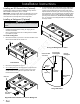
Planning the Installation Product Dimensions All tolerances: ±1/16” (±1.6mm) Gas Regulator Access, Cover Removed GAS - ELECTRICAL ACCESS DIMENSIONS Model A B C D E* ER36D 5 5/8” (142.9mm) 18 3/8” (466.7mm) 10 3/4” (273.0mm) 13 11/16” (347.7mm) 7/8” (22.2mm) ER48D 3 13/16” (96.8mm) 18 11/16” (474.7mm) 9 3/8” (238.1mm) 13 3/4” (349.3mm) 1 1/8” (28.6mm) * The diameter on models equipped for use in Canada is ¼” (6.4mm) larger than those stated.
Planning the Installation Cabinet Layout Gas and Electrical Service • To reduce the risk of personal injury and to reduce accumulated smoke in the room, Dacor strongly recommends installing a range hood. A range hood should project horizontally a minimum of 5 inches beyond the face of the cabinets. The shaded area shown denotes the location of the gas inlet and the electrical junction box/receptacle. This is the recommended location.
Installation Instructions Preparing for Installation WARNING • • If the gas or electric service provided does not meet the product specifications, do not proceed with the installation. Call the dealer, the gas supplier or a licensed electrician. Before installing the range, you must locate and secure the anti-tip bracket to the floor. WARNING Do not connect the unit to gas or power before proceeding with the following sections. Level and Adjust the Range Height 1.
Installation Instructions Installing an ERV Raised Vent (Optional) Install the ERV raised vent before installing the range. See the ERV installation instructions, part no. 103106. IMPORTANT: The ERV series raised vent attaches to the narrow back portion of the ERV style cutout. It is self-supporting in the cutout and does not actually attach to the range itself. Installing a Backguard (Optional) 4.
Installation Instructions Installing a Backguard (Continued) 5. 6. Fasten the backguard and the stainless steel trim piece in place with the five (5) existing chrome plated screws. Removing the Oven Door WARNING • Secure the rear of the backguard to the back of the range with the eight (8) existing hex screws. • Chrome Plated Screw, 5 Places Do not attempt to disengage the hinge catches with the door removed from the oven. The hinge springs could release causing personal injury.
Installation Instructions Electrical Connection WARNING • • • • • Wire the range only in compliance with local ordinances. Improper connection of the electrical wiring can cause an electric shock hazard and damage the appliance. Dacor is not responsible for damages resulting from improper installation. Connect the ground terminal (or lead) on the appliance to a grounded, metallic, permanent wiring system or grounding conductor. Do not use an extension cord with this appliance.
Installation Instructions L1 Terminal Neutral Terminal L2 Terminal Jumper Removed Grounding Screw Red Wire Green Wire White Wire Black Wire Conduit Strain Relief Nut Connecting 4 Wire Conduit to Range L1 Terminal Neutral Terminal Jumper Link L2 Terminal Black Wire White Wire Bare Wire Connections Red Wire Conduit Strain Relief Nut Loop and Spade Terminal Connections Connecting 3 Wire Conduit to Range Where Local Code Permits 11
Installation Instructions Electrical Connection (continued) Connecting the Conduit to the House Electrical Junction Box Connection to power supply Junction Box WARNING Do not connect the green appliance wire to the neutral (white) supply wire unless local building codes permit. Wire Nut, 4 Places NOTES: • The power supply must be properly polarized. Reverse polarity will result in continuous sparking of the electrodes, even after flame ignition.
Installation Instructions Junction Box Connection to power supply Separate No. 10 (minimum copper grounding wire Fasten clamp tightly on pipe Wire Nut, 4 Places Connect to appliance (page 10) Junction Box - 4 Wire Connection with External Ground No.
Installation Instructions Electrical Connection (continued) 5. Slide the end of the appliance cord into the strain relief from the bottom of the box Connecting an Appliance Wire to the Range - Where Local Code Permits 6. Connect the white (neutral) wire to the neutral terminal in the box. 7. Connect the L1 wire to the L1 power supply terminal in the box. 8. Connect the L2 wire to the L2 power supply terminal in the box. 9.
Installation Instructions Gas Supply Connection WARNING • Bare Wire Connections • • • Loop and Spade Terminal Connections • • L1 Terminal Neutral Terminal • L2 Terminal Make sure the gas supply valve is off and that the power to the range is turned off at the circuit breaker or fuse box prior to connecting the gas line. Do not apply excessive pressure when tightening gas connections and fittings. Do not use Teflon tape or plumber’s putty on gas flex line connections.
Installation Instructions Final Installation 1. Peel the protective coating off of the range, including the door. 2. Adjust the legs to the desired height. 3. Carefully slide the range into position in the cut-out. The rear anti-tip leg should engage the anti-tip bracket.
Installation Instructions Installing the Burner Components WARNING Never attempt to operate the cooktop section of the range with any of the burner rings, burner caps or grates removed. • Remove the burner rings, burner caps and grates from their shipping packages. • Install the burners as shown. The location, type and size of the burners varies with the range model number. • Gently set the grates on top of the spill tray. Put the legs of each grate inside the corresponding dimples.
Installation Instructions Verifying Proper Operation Installation Checklist Prior to operating the cooktop or oven, please read the accompanying use and care manual carefully. Important safety, service and warranty information is contained within the use and care manual. 1. Before beginning the test procedure, ensure that all cooktop control valves are in the “OFF” position, and all burner rings, burner caps and grates are properly positioned on the cooktop frame.
Notes 19
Notes 20
Dacor ● 1440 Bridge Gate Drive, Diamond Bar, CA 91765 ● Tel: (800) 793-0093 ● FAX: (626) 403-3130 ● www.Dacor.