Installation Instructions Distinctive™ Wall Mount Range Hood Models DH3006S, DH3606S ® Approved for use with all dacor ranges and cooktops. Tested in accordance with the latest edition of ANSI/UL 507 standard for electric fans and can/csa-c22.2 no. 113 standard for fans and ventilators. Part No. 105811 Rev.
Table of Contents Important Safety Instructions........................................... 1 Important Information About Safety Instructions............... 1 General Safety Precautions.............................................. 2 Product Specifications ..................................................... 3 Specifications and Dimensions......................................... 3 Planning the Installation.................................................... 4 Cabinet Layout.................................
Important Safety Instructions Important Information About Safety Instructions • • Safety Symbols and Labels DANGER The Important Safety Instructions and warnings in these instructions are not meant to cover all possible problems and conditions that can occur. Use common sense and caution when installing, maintaining or operating this or any other appliance. Always contact the Dacor Customer Service Team about problems and conditions that you don’t understand.
Important Safety Instructions CAUTION For general ventilating use only. Do not use to exhaust hazardous or explosive materials and vapors. General Safety Precautions To reduce the risk of fire, electric shock, serious injury or death when using this appliance, follow basic safety precautions, including the following: warning • Do not install or operate this hood if it has been damaged, dropped, has damaged electrical wires or is not working properly.
Product Specifications Specifications and Dimensions 11 7/8 ” (30.2 cm) Tolerances: +1/16” (1.6 mm) -0, unless otherwise stated. Number of fan speeds A Infinite Mesh type, dishwasher safe (Optional baffle type available, order part number AHBF2) Filters Exhaust 6” (15.2 cm) 8-inch Total Connected Load Lights 120 Vac, 60 Hz., 2 Amp. Max. (10.0 Amp Max. surge) 120 Vac, 75 W halogen Number of lights 2 Number of filters 2 Exhaust Outputs 1 23 5/8” (60.
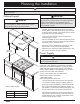
Planning the Installation warning Observe all governing codes and ordinances during planning and installation. Contact your local building department for further information. Cabinet Layout important See the diagram for minimum installed distance from the hood to the cooktop surface. The minimum specified distance may be higher for the particular range or cooktop in use. Check the manufacturers specifications for the cooktop or range.
Planning the Installation Planning the Ductwork warning • To prevent combustion by-products, smoke or odors from entering the home and to improve efficiency, tape all duct joints securely. • Use only ductwork deemed acceptable by state, municipal and local codes. • Range hoods may interrupt the proper flow of smoke and combustion gases from furnaces, gas water heaters and fireplaces.
Installation Instructions Verify the Package Contents B A Unpack the parts box and verify that all parts have been included according to the parts list. If any item is missing or damaged, please contact the dealer immediately. Do not install a damaged or incomplete appliance. Make sure you have everything necessary for proper installation before proceeding.
Installation Instructions Electrical Service Installation Duct Cutout Install a junction box in the vicinity of the hood electrical access holes according to local codes. Install it above the hood. The diagram below shows the suggested location. 1. Using a pencil, draw the vertical center line for the range hood on the surface above the hood mounting location.
Installation Instructions Hanging the Range Hood Ductwork Installation warning warning Hanging the range hood requires two people. Do not attempt to lift the hood without assistance. 1. Remove the filters from the bottom of the hood to reduce the chance of damage during installation. Put them in a safe location. 2. Remove the plastic coating from the outside of the hood. 3. Lift the hood into its final position and hold it in place.
Installation Instructions 3. Connect the hood wiring to an electrical junction box on a dedicated circuit. See page 4 for specifications. Connect it according to one of the wiring diagrams below. To house circuit breaker panel or fuse box Wire nut, 3 places WHITE WHITE GREEN GREEN BLACK BLACK Junction box To range hood UL/CSA approved NEMA strain relief 3 Wire Connection to Junction Box Separate No.
Installation Instructions Light Bulb Installation 1. Attach the included suction cup to one of the provided light bulbs. Verifying Proper Operation Control knobs 2. Insert it into one of the light fixtures. 3. Screw it into place and remove the suction cup. 4. Repeat for the remaining light fixture. Filters 2 1. Install the filters. 2. Turn on power at the circuit breaker panel or fuse box. 3. Turn the light and fan control knobs clockwise and make sure that the lights and fan operate properly.
Installation Instructions Installation Checklist warning • To ensure a safe and proper installation, the following checklist should be completed by the installer to ensure that no part of the installation has been overlooked. • Proper installation is the responsibility of the homeowner. The importance of proper installation of your Dacor range hood cannot be overemphasized.
Wiring Diagram GROUND NEUTRAL LINE WH BLK HALOGEN LIGHTS (2) WH BLK FAN MOTOR WH 12 M LAMP DIMMER BLK FAN SWITCH BLK
Dacor ● 14425 Clark Avenue, City of Industry, CA 91745 ● Phone: (800) 793-0093 ● Fax: (626) 403-3130 ● www.dacor.