Installation Distinctive TM Electric Instructions Cooktop Models DECT304, DECT365 _D PJ eo _o Lr) O Fran_:is • voir page 1 1 Espa_ol: consuhe la p6gina 21
Table of Contents Page Special Warnings .............................................................. WARNING 3 Product Dimensions and Cutout Requirements ............. 4 ,, Important Preparation Suggestions ..................................... 5 Cooktop installation .......................................................... 6 • Electrical Connections ...................................................... 9 This is the safety alert symbol.
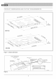
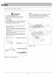
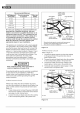
m) DECT304 2_ J(5,18cm) DECT365 Figure 1. Chassis dimensions CUTOUT DiMENSiONS WIDTH OF CUT A SEE NOTE R 1-1/2" (3.8 cm) MIN CLEARANCE DEPTH OF CUT B FROM EDGE OF CUTOUT AND FRONT EDGE OF Hole in cabinet floor for conduit COUNTERTOP 1" (2,5cm) routing: 3 1/2" (9 cm) deep x 2 1/2" (6.
CABINET REQUIREMENTS G WALL COVERING CABINETS, AND COUNTERTOP MUST WITHSTAND HEAT UP TO 200°F (93°C) INST 023-2 Fiaure 3. Cabinet CUTOUT WIDTH dimensions A and reauirements B C D E F G 28-11/16" 30" (76.2cm) i 19-1/4" (72.9 cm) to I(49.0 cm) to 28 15/16" i 19-9/16" (73.5 cm) 34-1/16" 36" (91.4 cm) (76.2 cm) min (49.7 cm) 18" (45.7 cm) min height from countertop to nearest cabinet i 19-1/4" (86,5 cm) to (49.0 cm) to 34-5/16" i 19-9/16" (87.2 cm) 130" 36" (91.
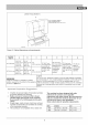
_00 10 _ Ho [)%LLA 0_ Step 1 Remove packaging materials and literature package from the cooktop before beginning installation. Remove installation manual from literature pack and read them carefully before you begin. WARNING = Excessive Weight Hazard Use two or more people to move and install cooktop. Failure to do so can result in back or other injury. • Cut Hazard Beware of sharp edges. Use the polystyrene ends when carrying the product.
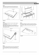
Step 2 Place a towel or table cloth onto the counter top. Lay the cooktop upside down onto the protected surface. BURNER BOX TABLE CLOTH Figure 8 Figure 6 Step 3 A foam tape is provided to seal the cooktop edges to the countertop. Apply tape approximately 1/16" (1.5 mm) from the glass edge to the underside of the cooktop glass. Use tape around the entire glass perimeter. Cut off excess where tape ends butt. Step 5 Four clamp brackets are provided to clamp the cooktop to the countertop.
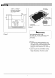
CONDUIT LOCATIONS OF ALUMINUM REFLECTIVE TAPE OPENING A: 12" (30,5 cm) MIN FROM BOTTOM OF COUNTERTOP AND ADJACENT CABINET (RIGHT SIDE) f I TAPE TOP AND VERTICAL SIDES OF ;UTOUT SOLID SURFACE COUNTERTOP INSTALLATION INST 005-2 Figure 11 f INST ..................................................................................................................
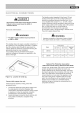
Disconnect power before servicing the product. Failure to do so could result in death or electrical shock. ®eneral information s ........... The flexible conduit (supplied) 4 feet long (123 cm) located at the right rear of the cooktop bottom box should be connected directly to junction box. Do not cut or lengthen the conduit. A U.L - or CSA - listed conduit connector must be provided at each end of the power supply cable (at the cooktop and at the junction box.
Recommended kW Rating on serial plate Minimum Circuit protection in amperes 3-WIRE CABLE FROM POWER SUPPLY Wire size (AWG) 0-4.8 20 12 4.9-6.9 30 10 7.0-9.9 40 8 10.0-11.9 50 8 12.0-14.9 60 6 RED WIRES w WIRE BARE OR GREEN WIRES 3=WIRE CABLE FROM COOKTOP / BLACK WlRES U.L.-OR CSA-MSTED CONDUIT CONNECTOR Where local codes permit connecting the frame-ground conductor to the neutral (white) junction box wire.
%3 © O O oO LO C_d C3 O'. o _J © © The Life of the Kitchen? Dacor • 600 Anton Blvd. Suite 1000 Costa Mesa, CA 92626 • Phone: (800) 793-0093 • Fax: (626)403-3130 • www.dacor.