
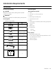
Installation Instructions

ENGLISH 13
Installation
Installation instructions
We recommend that a qualied technician install the
hood. It is the installer’s responsibility to ensure the hood
complies with the installation clearances specied for the
product.
• It is recommended that the vent system be installed
before the hood is installed.
• If possible, disconnect and remove any cooking
appliance from beneath the hood area to provide
easier access to the rear wall.
• Before making cutouts, make sure there is proper
clearance within the ceiling or wall for the exhaust
vent.
• Conrm that all installation parts have been removed
from the shipping carton.
1. Turn off the power at the circuit breaker panel or fuse
box.
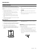
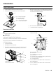
2. Determine which venting method to use: vertical or
horizontal.
NOTE
This hood is factory set to vent through the top air
exit.
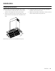
3. Select a at surface for assembling the hood. Place a
covering over that surface.
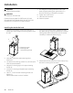
Wall installation
1. Turn power OFF at the service panel. Lock service
panel to prevent power from being turned ON.
2. Ensure that the installation height from the bottom of
the hood to the cooking surface will be maintained.
3. Mark a reference centerline on the wall.
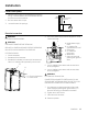
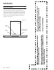
4. Tape template in place, aligning the template
centerline (B) and bottom of template (C) with hood
bottom line and with the centerline marked on the
wall (A).
A
B
C
DRILL 4 (TWO)
3
/
16
˝ (4.8 mm) PILOT HOLES THROUGH
STUDS OR REAR WALL SUPPORTS
PERCER QUATRE (4) AVANT-TROUS DE
3
/
16
˝ (4.8 mm)
DANS LES MONTANS O U LES SUPPORTS DU MUR
ARRIÈRE
HAGA 4 O RIFICIOS D E
3
/
16
˝ (4.8 mm) S OBRE L OS
SOPORTES DE LA PARED TRASERA
ALIGN BOTTOM EDGE WITH PENCIL LINE INDICATING
BOTTOM OF THE HOOD
ALIGNER LA LIGNE HORIZONTALE AVEC LA LIGNE DE
CRAYON INDIQUANT LA PARTIE INFÉRIEURE DE LA HOTTE
ALINEE LA LÍNEA HORIZONTAL CON LA LÍNEA DE LÁPIZ QUE
INDICA LA PARTE INFERIOR DE LA CAMPANA
HORIZONTAL LINE / LIGNE HORIZONTALE / LINEA HORIZONTAL INSTALLATION HEIGHT / HAUTEUR DE L’INSTALLATION
ALTURA DE INSTALACIÓN
NOTE: TEMPLATE MAY NOT BE TO SCALE.
MEASURE ALL DIMENSIONS.
REMARQUE: LE MODÈLE NE POURRAIT PAS ÊTRE
EN ÉCHELLE. MESUREZ TOUTES LES DIMENSIONS.
NOTA: LA PLANTILLA PUEDE NO ESTAR A ESCALA
REAL. EFECTUE TODAS LAS MEDICIONES.
REAR WALL
MOUNTING TEMPLATE
GABARIT DE MONTAGE
DU MUR ARRIERE
PLANTILLA DE MONTAJE
PARA PARED POSTERIOR
VE
RTICAL CENTERLINE / AXE CENTRAL VERTICAL / LÍNEA CENTRAL VERTICAL
DIM0139475
10
1
/
16
˝ (256 mm)
10˝ (254 mm)
4
9
/
16
˝ (115 mm) 15
5
/
8
˝ (397 mm)
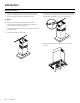
5. Mark centers of the fastener locations through the
template to the wall.
IMPORTANT: All screws must be installed into wood. If
there is no wood to screw into, additional wall framing
supports may be required.
6. Remove the template.
7. Drill ³⁄₁₆” (4.8 mm) pilot holes at all locations where
screws are being installed into wood.
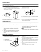
8. Install the 2 - 5 x 45 mm mounting screws with 2 8 -
40 mm anchors. Leave a ¹⁄₄”(6.4 mm) gap between
the wall and the back of the screw head to slide hood
into place.
¹⁄₄″ (6.4 mm)