Installation Instructions Discovery Island (Ceiling Mount) Range Hoods ® Models: DHI361, DHI421, DHI482 and DHI542 ® APPROVED FOR USE WITH ALL DACOR RANGES AND COOKTOPS. IMPORTANT: INSTALLATION OF THIS HOOD REQUIRES A CHIMNEY KIT, DACOR PART # DHICH. Part No. 101744 Rev.
Table of Contents Important Safety Instructions...................................... 1 Important Information About Safety Instructions.......... 1 General Safety Precautions......................................... 2 Installation Specifications ........................................... 3 Performance Specifications......................................... 3 Electrical Specifications............................................... 3 Dimensions.................................................................
Important Safety Instructions Important Information About Safety Instructions Safety Symbols and Labels DANGER ■■ The Important Safety Instructions and warnings in these instructions are not meant to cover all possible problems and conditions that can occur. Use common sense and caution when installing, maintaining or operating this or any other appliance. ■■ Always contact the Dacor Customer Service Team about problems and conditions that you don’t understand.
Important Safety Instructions General Safety Precautions To reduce the risk of fire, electric shock, serious injury or death when using your appliance, follow basic safety precautions, including the following: WARNING • If the information in this manual is not followed exactly, a fire or explosion may result causing property damage, personal injury or death. • Do not install or operate this hood if it has been damaged, dropped, has damaged electrical wires or is not working properly.
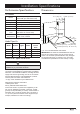
Installation Specifications Performance Specifications Dimensions All Models Tolerances: ±1/16” (±1.6 mm), -0 unless otherwise stated 15 ¾” (40.0 cm) 600 CFM* (for single blower units) 1200 CFM* (for dual blower units) Blower Speeds 12 Vac, 20 Watt halogen Filters Baffle type, dishwasher safe Exhaust 8-inch Finish 430 stainless steel Total Connected 120 Vac, 60 Hz., Load (See below for current draw) Circuit Requirement 12 9/16” (31.
Installation Specifications Planning the Location Recirculating Configuration WARNING • Observe all governing codes and ordinances during planning and installation. Contact your local building department for further information. • The range hood is heavy. To prevent personal injury and property damage caused by the hood coming loose from the ceiling, use only the hood mounting bracket provided with the unit. ■■ Carefully check the location where the hood is to be installed.
Installation Specifications Ducted Installations - Planning the Duct Work WARNING • To prevent combustion by-products, smoke or odors from entering the home and to improve efficiency, tape all duct joints securely. • Use only duct work deemed acceptable by state, municipal and local codes. • DO NOT install an additional in-line or external blower to increase the length of the duct run. Even small differences between blower air flow rates can greatly reduce the air draw of the hood.
Installation Instructions Verify the Package Contents Assemble the Hood Unpack the parts boxes and verify that all required components have been provided. The parts shown below include the contents of the chimney kit (DHICH), which is required for installation. If any item is missing or damaged, please contact the dealer immediately. Do not install a damaged or incomplete appliance. 1. Place the hood assembly on a soft surface with the bottom side down during assembly to avoid damage.
Installation Instructions WARNING • Observe all governing codes and ordinances during installation. Contact your local building department for further information. • A qualified technician must complete the installation of this built-in appliance. The owner is responsible to make sure the hood is properly installed. • Do not install the range hood unless the power supply provided meets the required Electrical Specifications (see page 3).
Installation Instructions 10. Put the top framework piece over the bottom framework piece as shown below. The mounting slots on the top piece must be up. 11. Use four machine screws to fasten the top piece to the bottom piece. The total height of the two pieces together must equal the required framework height determined above. 12. Remove the protective plastic covering from both pieces of the chimney assembly. Do not remove the protective tape strips from the inside.
Preparing for Installation Install the Duct Work Final Electrical Installation WARNING Do not use screws to attach the duct work to the hood exhaust outlet. Use duct tape only. Screws may prevent the damper flaps on the top of the hood from opening. ■■ If installing the unit with a recirculating kit, skip to Final Electrical Installation. Otherwise, install the duct work system according to the specifications on page 5. ■■ Lift the chimney up and reach inside the framework to access the hood exhaust.
Installation Instructions Final Chimney Assembly WARNING Be careful not to pinch the electrical wires while assembling the chimney. 1. Move the chimney up toward the ceiling. Line up the holes on the side of the chimney, above the vents, with the holes on the side of the mounting bracket. Verifying Proper Operation 1. Make sure power is switched on at the circuit breaker panel or fuse box. 2.
Installation Instructions Installation Checklist WARNING • To ensure a safe and proper installation, the following checklist should be completed by the installer to ensure that no part of the installation has been overlooked. • Proper installation is the responsibility of the homeowner. The importance of proper installation of your Dacor range hood cannot be overemphasized. □□ Is the mounting bracket properly attached to the ceiling according to the instructions on page 7.
Wiring Diagrams YELLOW/GREEN TO BLOWER MOTOR MAIN POWER SWITCH TRANSFORMER LIGHT FIXTURES TRANSFORMER LIGHT FIXTURES EXTERNAL BLOWER CONNECTION Please note—the layout on the PC Board shown above may vary— however all wires are coded and the connections on the PC Board are also coded with the same number/letters.
Wiring Diagrams YELLOW/GREEN MAIN POWER SWITCH TO BLOWER MOTOR TO BLOWER MOTOR TRANSFORMER LIGHT FIXTURES TRANSFORMER LIGHT FIXTURES EXTERNAL BLOWER CONNECTION Please note—the layout on the PC Board shown above may vary— however all wires are coded and the connections on the PC Board are also coded with the same number/letters.
Dacor ● 14425 Clark Avenue, City of Industry, CA 91745 ● Phone: (800) 793-0093 ● Fax: (626) 403-3130 ● www.dacor.