Installation Instructions Millennia Island (Ceiling Mount) Range Hoods ® For use with models: DHI361, DHI421, DHI482, DHI542 and DHI602 ® Approved for use with all dacor ranges and cooktops. Part No. 101744 Rev.
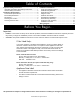
Table of Contents Important Safety Instructions........................................... 1 Important Information About Safety Instructions............... 1 General Safety Precautions.............................................. 2 Installation Specifications ................................................ 3 Performance Specifications.............................................. 3 Electrical Specifications.................................................... 3 Dimensions...................................
Important Safety Instructions Important Information About Safety Instructions • • Safety Symbols and Labels DANGER The Important Safety Instructions and warnings in these instructions are not meant to cover all possible problems and conditions that can occur. Use common sense and caution when installing, maintaining or operating this or any other appliance. Always contact the Dacor Customer Service Team about problems and conditions that you don’t understand.
Important Safety Instructions General Safety Precautions To reduce the risk of fire, electric shock, serious injury or death when using your appliance, follow basic safety precautions, including the following: warning • If the information in this manual is not followed exactly, a fire or explosion may result causing property damage, personal injury or death. • Do not install or operate this hood if it has been damaged, dropped, has damaged electrical wires or is not working properly.
Installation Specifications Performance Specifications Dimensions All Models Tolerances: ±1/16” (±1.6 mm), -0 unless otherwise stated 15 ¾” (40.0 cm) 600 CFM* (for single blower units) 1200 CFM* (for dual blower units) Blower Speeds Lights 12 Vac, 20 Watt halogen Filters Baffle type, dishwasher safe Exhaust 8-inch Finish 430 stainless steel Total Connected 120 Vac, 60 Hz, Load (See below for current draw) Filters Baffle type, dishwasher safe Circuit Requirement 12 9/16” (31.
Installation Specifications Planning the Location Planning the Duct Work warning warning • Observe all governing codes and ordinances during planning and installation. Contact your local building department for further information. • To prevent combustion by-products, smoke or odors from entering the home and to improve efficiency, tape all duct joints securely. • The range hood is heavy.
Installation Specifications Calculating the Maximum Duct Run Length Duct Work Design Tips The maximum straight duct length for the hood is 50 feet. To determine the actual maximum duct run, subtract the equivalent length of each elbow, transition and cap from 50 feet. Wherever possible, reduce the number of transitions and turns to as few sharp angles as possible. Two staggered 45° angles are better than one 90°.
Installation Instructions warning • Observe all governing codes and ordinances during installation. Contact your local building department for further information. • A qualified technician must complete the installation of this built-in appliance. The owner is responsible to make sure the hood is properly installed. • Do not install the range hood unless the power supply provided meets the required Electrical Specifications (see page 3).
Installation Instructions 6. Separate the bottom framework piece from the top framework piece. The top frame work piece has 5-inch slots on the sides. The bottom piece has a series of holes on the sides. 7. Position the bottom framework piece on top of the hood. Slide the studs on the top of the hood into the holes on the bottom of the framework piece. The cutouts for the wiring allow the bottom framework piece to fit on only one way. If it does not fit properly, turn it 180° so that the cut-outs line up.
Installation Instructions Hang the Hood Install the Duct Work warning warning To prevent personal injury, do not rely on the mounting springs to hold the hood assembly in place on the ceiling. Once the hood is hooked in place IMMEDIATELY secure the framework to the mounting bracket as described below. 1. Before raising the hood into position, lift it up and orient it so that the control panel faces the same direction as the front of the cooktop or range. 2.
Preparing for Installation Final Electrical Installation warning • Final Chimney Assembly warning To avoid electric shock or fire hazard, prior to connecting the electrical wiring to the hood, make sure that power to the hood power supply line is turned off at the circuit breaker panel or fuse box. • Improper connection of the hood electrical wiring may create an electric shock or fire hazard and may result in damage to the hood’s electrical system. See page 3 for specifications.
Installation Instructions Verifying Proper Operation Installation Checklist 1. Make sure power is switched on at the circuit breaker panel or fuse box. 2. If the control panel is not lit, remove the filter(s) and turn on the main power switch located behind the filters on the underside of the hood. Replace the filter(s). 3. Touch the light key. Verify that all the lights come on. 4. Touch the light key again to turn the lights off. 5. Touch the blower “+” key once and release.
Wiring Diagrams YELLOW/GREEN TO BLOWER MOTOR MAIN POWER SWITCH TRANSFORMER LIGHT FIXTURES TRANSFORMER LIGHT FIXTURES EXTERNAL BLOWER CONNECTION Please note—the layout on the PC Board shown above may vary— however all wires are coded and the connections on the PC Board are also coded with the same number/letters.
Wiring Diagrams YELLOW/GREEN MAIN POWER SWITCH TO BLOWER MOTOR TO BLOWER MOTOR TRANSFORMER LIGHT FIXTURES TRANSFORMER LIGHT FIXTURES EXTERNAL BLOWER CONNECTION Please note—the layout on the PC Board shown above may vary— however all wires are coded and the connections on the PC Board are also coded with the same number/letters.
Dacor ● Phone: (800) 793-0093 ● FAX: (626) 403-3130 ● www.Dacor.