Service Manual Built-In Dishwasher
Table Section 1 - Safe Servicing Practices. ............................ 1-1 Section 2 - Operation....................................................2-1 Static Fill...............................................................................2-1 Dynamic Fill..........................................................................2-1 Wash System........................................................................2-2 Soil Sensing.........................................................................
Section 1 - Safe Servicing Practices Section 1 - Safe Servicing Practices To avoid personal injury and/or property damage, it is important that Safe Servicing Practices be observed. The following are some limited examples of safe practices: 1. D O NOT attempt a product repair if you have any doubts as to your ability to complete it in a safe and satisfactory manner. 2. Before servicing or moving an appliance: • Remove the power to unit. • Turn off the gas supply. • Turn off the water supply. 3.
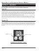
Dacor Built-In Dishwasher Service Manual Section 2 - Operation In order to address service issues with the Dacor Built-In Dishwasher, the primary elements of its operation are described below, as well as its physical components. Static Fill The cycle begins by activating the drain pump, ensuring the sump is empty. Operation then proceeds to the fill stage where the fill valve regulates inlet water to 1.08 GPM between 20 and 120 psi.
Section 2 - Operation Wash System Once filling is complete, the dishwasher enters the pre-wash phase. The pre-wash phase conditions the soil with water and detergent to prepare it for removal in the main wash phase. Once water enters the tub, the pump draws the water into the sump through a primary filter at the bottom of the tub to prevent food from circulating through the wash system and redepositing on the dishes. In the center of the primary filter is the lower spray arm and drain filter assembly.
Dacor Built-In Dishwasher Service Manual Main Wash/Temp Assure After the final reading by the soil sensor, the unit drains before starting to fill for the main wash. The tub fills, with the wash motor starting after the low level pressure switch is activated. The detergent dispenser now opens, introducing detergent into the wash cycle.
Section 2 - Operation Rinse Phases The first rinse phase follows the pre-wash portion of a wash cycle. During this rinse phase, the motor ramps up by 100RPM/second to full speed (2800RPM). Once at full speed, however, the motor will cycle between 1600RPM and 2800 RPM throughout the rest of this rinse phase. This motor action aids in the removal of food from the dishes so it can be filtered from the water. The final rinse phase begins, following the end of the main wash.
Dacor Built-In Dishwasher Service Manual Section 3 - Cycle, Systems & Components Knowledge of the dishwasher’s cycles and systems is necessary in diagnosing any potential operational problems. Methods for diagnosing these problems, such as taking resistance readings and testing for closed circuits are outlined in the following section as well. Dishwasher Control All of the functions and operations of this dishwasher are dictated and monitored by the electronic control.
Section 3 - Cycle, Systems & Components Component Function Test (continued) Entering the Water/Service Test From Power Failure While the control displays power failure or flashing lights, press and hold the Short wash and the Rinse & Hold pads simultaneously for one second. The dishwasher will start through the test cycle. From Idle With no cycle selected and the dishwasher sitting idle, press and hold the Hi-temp and the Start pads simultaneously for one second.
Dacor Built-In Dishwasher Service Manual Component Function Test (continued) Soil Sensor Test Mode This tests the sensor for proper operation as well as the value that the sensor is detecting. 1. To activate the test you must press and hold the Heavy and Start pads simultaneously. 2. When the test mode is activated, the digit display will show the turbidity value of the sensor. This display will be a voltage reading in the decimal value. 3. To terminate this test press the Start pad.
Section 3 - Cycle, Systems & Components Inlet Water Valve (continued) To Check Inlet Water Valve 1. Disconnect dishwasher from power supply. 2. To access electrical connections to valve, remove lower front panel. 3. Using ohmmeter, check between P3-5 (yellow wire) and P3-8 (white wire). The resistance reading of the solenoid coil should be 1126 ohms. Figure 8 Pressure Switch Assembly The pressure switch assembly consists of a low water level switch and a high water level switch with common bracket.
Dacor Built-In Dishwasher Service Manual Low Water Level Switch (continued) Checking Low Water Level Switch 1. Disconnect power to dishwasher. 2. Gain access to electronic control and check between P3-9 (orange wire) and P3-8 (white wire). This should be an open contact. 3. These wires are connected to center terminal #1 and terminal to the right of center #3. 4. Add water to sump to close switch.
Section 3 - Cycle, Systems & Components High Water Level Switch (continued) Checking High Water Level Switch 1. Checking continuity through the high water level switch is easier at the control. 2. Disconnect power to dishwasher. 3. Gain access to electronic control and check for continuity between the L1 black wire and P3-6 (brown wire). This contact should be open. 4. These wires are connected to center terminal #1 and terminal to the right of center #3 on the switch. 5.
Dacor Built-In Dishwasher Service Manual Heater The heater in this dishwasher is inline between the wash motor and the delivery tube. The 1200W heater wraps around a stainless steel core tube. The heater can only be energized, during a wash cycle, while the wash pump is running after the low level pressure switch has been activated. Water is heated as it passes through the heater to the center spray arm. This heater has internal thermal protection.
Section 3 - Cycle, Systems & Components Checking the Soil Sensor 1. While in idle mode, simultaneously press and hold Heavy Wash and Start/Cancel buttons. • This activates the sensor value test. • If a number does not display, continue with the test. 2. Disconnect dishwasher from power supply. 3. Check soil sensor circuit at control. • A resistance reading should be taken between P2-1 black and P2-7 white at the control for the emitter.
Dacor Built-In Dishwasher Service Manual Dispenser The dispenser consists of two dispensers in one housing, controlled by the use of one wax motor actuator. The first time the actuator is energized in the cycle, detergent is dispensed. The second time the actuator is energized, rinse agent is dispensed. The rinse aid half of the dispenser can be adjusted to meet the customer’s needs. This is done by removing the cap from the dispenser and adjusting the arrow inside to a higher number.
Section 3 - Cycle, Systems & Components Fan Dry Unit Dishes are dried with a fan driven condensate system. This system is made up of (refer to Figures 20, 21): 1. Fan Dry Motor 2. Air Intake 3. Condensate Duct 4. Condensate Vent As the dishwasher completes its final drain, the fan dry motor forces saturated air across cool baffles in the condensate duct, resulting in the removal of moisture from the air. The cooler, drier air and condensed water are returned to the tub through the condensate vent.
Dacor Built-In Dishwasher Service Manual Section 4 - Service & Disassembly Safety Precautions Always turn off the electric power supply before servicing electrical components, testing with an ohmmeter, or replacing parts. Refer to Safe Servicing Procedures at the front of this manual before servicing the dishwasher. All voltage checks should be made with a voltmeter having a full scale range of 130 volts or higher.
Section 4 - Service & Disassembly Dispenser 1. Disconnect dishwasher from power supply. 2. Remove outer door panel (see previous section for detailed instructions). 3. Remove six screws securing dispenser assembly to inner door panel. Retainer brackets on the top and bottom may also need to be removed. figure 24 Lower Access Panel 1. Remove bottom kick plate. 2. Remove screws on each side of lower access panel. (See Figure 25) Remove these screws 3. Remove access panel.
Dacor Built-In Dishwasher Service Manual Upper Spray Arm 1. The center of the upper spray arm is a locking mount. 2. Turn upper spray arm and mount counterclockwise to remove. (See Figure 28) 3. To reinstall upper spray arm, line up locking posts in center mount with locking tabs on upper spray arm support. Turn clockwise until it locks securely. Turn center of spray arm to remove figure 28 Lower Spray Arm 1. Remove lower rack. 2. Lower spray arm snaps onto volute cover. All 3 dishwasher spray arms 3.
Section 4 - Service & Disassembly Center Spray Arm and Upper Rack Manifold 1. Remove upper rack and place rack upside down on a flat surface. 2. Place blade of a very thin putty knife between retaining ring and center spray arm. Lightly twist knife to lift arm from retaining ring. (See Figure 30) 3. Remove manifold from rack by compressing tube retainer clips and sliding tube backwards to clear front mount. Reverse this procedure to reattach manifold. 4.
Dacor Built-In Dishwasher Service Manual Upper Spray Arm Mount 1. Replacing upper spray arm mount requires removal of cabinet. See section on cabinet removal for detailed instructions. 2. Set dishwasher upright and remove upper spray arm. The mount pushes into the top of the tub with a rubber grommet. An arm on the mount holds it in place to prevent turning during removal/ installation of the upper spray arm. 3. Reverse procedure for reassembly. Bottom Door Seal 1.
Section 4 - Service & Disassembly Water Valve 1. Disconnect dishwasher from power supply. 2. Turn off water supply to dishwasher. 3. Remove kick plate and lower access panel. Removal of outer door panel may be needed to gain access to necessary parts. 4. Remove wire connect and water supply line. 5. Remove two mounting screws holding water valve to front frame. 6. To remove fill hose from valve, rotate water valve. Then remove valve. 7. Reverse procedure to reinstall. CABINET REMOVAL 1.
Dacor Built-In Dishwasher Service Manual Door Spring 1. Remove dishwasher cabinet. See previous section detailed instructions. 2. Raise spring support rod out of mounting hole of “C” arm. (See Figure 38) 3. Reinstall door spring using reverse procedure. End of spring rod goes into hinge Spring Glide Spring Spring Rod figure 37 figure 38 Hinge “C” Arm 1. Remove dishwasher cabinet. See CABINET REMOVAL for detailed instructions. 2. Remove door spring. See previous section for detailed instructions. 3.
Section 4 - Service & Disassembly Door Seal Retainer 1. Remove dishwasher cabinet. See Cabinet Removal for detailed instructions. 2. Place dishwasher in an upright position and remove door seal. See previous section for detailed directions. 3. Remove screws (across the top and on both sides of the unit) that mount door seal retainer to tub. 4. Make sure the retainer gasket is in place and not torn before reinstalling the retainer. 5. Reverse order to complete assembly. Pressure Switch Assembly 1.
Dacor Built-In Dishwasher Service Manual Thermistor/Soil Sensor 1. Disconnect dishwasher from power and water supplies. Remove drain line. 2. Remove dishwasher from countertop. 3. Lay dishwasher on its back on a protective pad. 4. Remove wire plug from sensor by lifting lock to release plug. 5. Push retainers away from sensor and remove sensor from sump. (See Figure 42) 6. To reinstall, apply lubricant to sensor seal. Line up location tab with appropriate slot in sump and lock in place. 7.
Section 4 - Service & Disassembly Drain Pump 1. Disconnect dishwasher from power and water supplies. Remove drain line. 2. Remove dishwasher from countertop. 3. Lay dishwasher on its back on a protective pad. 4. Remove wires from drain pump. 5. Removing coupling hose with drain pump aids in pump removal from sump. 6. The locks holding the pump to the sump are located on both ends of the sump mount. Using a small blade screwdriver, push up on the locks, to release the pump. (See Figure 46) 7.
Dacor Built-In Dishwasher Service Manual Wash Motor (continued) front mount – figure 48 rear mount – figure 49 Capacitor 1. Disconnect dishwasher from power and water supplies. Remove drain line. 2. Remove dishwasher from countertop. 3. Lay dishwasher on its back on a protective pad. 4. Capacitor is mounted to back frame of the unit using a mounting nut. 5. Remove cap and wires. 6. Reinstall using reverse procedure.
Section 4 - Service & Disassembly Blower Assembly 1. Remove dishwasher cabinet. See CABINET REMOVAL for detailed instructions. Locking Tabs 2. After cabinet is removed, set unit upright. 3. From inside of the tub, depress retaining clips. (See Figure 54) Blower assembly is removed from top outside of tub. 4. Remove blower from side duct and remove wires from blower motor. 5. Reverse procedure to reinstall. figure 54 Sump 1. Disconnect dishwasher from power and water supplies. Remove drain line. 2.
Dacor Built-In Dishwasher Service Manual Side Vent and Fill Hose 1. Remove dishwasher cabinet. See CABINET REMOVAL for detailed instructions. Vent Grate 2. With cabinet removed, set unit upright. 3. Remove fill hose from side vent by removing hose clamp. Fill Hose Location 4. Unscrew (counterclockwise) vent grate from left side wall inside tub. 5. Remove side vent. 6. Reverse procedure to reinstall.
Section 5 - Troubleshooting Tips SYMPTOM CHECK THE FOLLOWING Dishwasher will not operate when turned on. 1. Fuse (blown or tripped). 2. 120 VAC supply wiring connection faulty. Motor hums but will not start or run. Motor trips out on internal thermal overload protection. 3. Electronic control board faulty. 4. Motor (inoperative, check resistances). 5. Door switch (open contacts). 6. Door latch not making contact with door switch. 7. Touch pad circuit defective. 8.
Dacor Built-In Dishwasher Service Manual SYMPTOM CHECK THE FOLLOWING REMEDY Dishwasher will not pump out. 1. 2. 3. 4. 5. 6. 7. Drain restricted. Defective drain pump. Air lock in drain hose. Blocked impeller. Open windings. Wiring or terminal defective. Electronic control board defective. 1. Water supply turned off. 2. Defective water inlet valve. 3. Check fill valve screen for obstructions. 4. Defective pressure switch. 5. Electronic control board defective. 6. Wiring or terminal defective. 1.
Section 6 - Parts Breakdown Door And Control Panel Page 6-1
MDW24 Dishwasher Component Connector Locations and Display Codes Component Name Wash Motor Wash Motor Tachometer Drain Pump Inlet Valve Dispenser Thermistor Dry Fan Component Connector locations P3-4 & P1 P3-10 & P3-11 P3-6 & P3-8 P3-5 & P3-8 P3-2 & P3-8 P2-7 & P2-6 P3-3 & P3-8 Resistance (Ω) 14 246 26 1126 1665 10000 2088 Display Codes (Readout) LO Low Liquid in the Rinse Aid Dispenser PF A Power Failure has occurred HO Water Heating Delay CL Close and latch the door 01-04 Hours delay before the dishwa