
Product data


Cabinet and Countertop Layout
WARNING
To av0id the risk Of fire or pers0nal njurY, al! I
and maximum specified c earances on this and the
fol ow ng pages must be maintained or exceeded
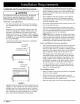
General Considerations
The minimum distance from the back of the cooktop
to a combustible rear wall is 2 1/2" (64 mm) minimum
(Figure 1).
Installation of a non-combustible material* (up to the
hood) or a backsplash is always recommended, and
mandatory if the distance to the back wall from the
cooktop is less than 2 1/2" (Figure 2). When installing
a backguard, use only Dacor model numbers AEB3009
or AEB3012 (for model DRT304S) AEB3609, AEB3612
(for model DRT366S).
* Consult local codes and ordinances for acceptable
non-combustible materials.
Combustible
rear wall %
2 112"(64 mm) Min. to
combustible rear walt
)_
,
FIGURE 1
N
\
N
\
N
\
\
\
N
\
\
\
Combustible
rear wall %
Backguard mandatory if
gap from back of cooktop
to combustible wall is less
than 2 1/2"
x.
4
N
\
N
\
\
\
\
\
\
\
\
FIGURE 2
Carefully check the location where the cooktop is to be
installed. For best performance, the cooktop should be
installed away from drafts caused by doors, windows
and heating and air conditioning outlets. To reduce the
risk of personal injury from reaching over a hot appli-
ance, avoid cabinet installations directly above.
To reduce the risk of personal injury and to reduce
accumulated smoke in the room, Dacor strongly recom-
mends installing a range hood. A hood should project
forward a minimum of five (5) inches beyond the face
of the cabinets.
The installation must allow access to the underside
of the cooktop for service and inspection purposes,
including the ability to turn off the cooktop gas supply
valve and electrical outlet.
All contact surfaces between the cooktop and the coun-
ter must be solid and level.
The countertop overhang on the sides of the cutout
shown on the following pages covers the recessed por-
tions of the cooktop behind the control panel and cre-
ates a seamless look for the installation.
IMPORTANT: When installing the cooktop into a lami-
nated or synthetic countertop, radius the corners of the
cutout to help avoid cracking. Consult the countertop
manufacturer's instructions for minimum corner radius,
reinforcement and heat protection requirements.
Gas and Electric Service Location
• The gas supply piping, gas shut-off valve and the elec-
trical outlet must be located so they do not interfere
with the cooktop when it is installed. If installing another
appliance in the cabinet below, allow for the routing of
gas and electrical service out the back of the unit.
• The shaded area on the facing page shows the rec-
ommended location of the gas inlet and the electrical
outlet. For replacement purposes, the location of the
existing utilities may be utilized provided they do not
interfere with the sides or rear of the cooktop. Check
local building codes for permissible utility locations.
• For best performance and to minimize gas pressure
loss, attach the gas supply regulator as close as pos-
sible to the cooktop gas inlet.
The installation must:
Allow for access to the gas shut-off valve and regulator
when the unit is installed.
Allow for access to the electrical outlet, when the
cooktop is in place so that the power cord may be eas-
ily disconnected if the unit needs service.
Allow the (32") power cord to reach the electrical outlet.
4 _mC_