Installation Instructions Built-In Wine Cellar DRW24980RAP/LAP
Contents Before You Begin 4 Important 4 Customer-Service Information 5 If You Need Help 5 Important Safety Instructions 6 State of California Proposition 65 Warning (US only) General Safety Precautions 6 7 Safety and Warning Information 11 Installation Safety 11 Installation Specifications 13 Installation Options 14 Product Specifications 16 Custom Panel Specifications Handle Specifications 17 18 Installation 20 Installation Requirements 21 Installation Preparation Grounding the
Installation Instructions 26 1. 2. 3. 4. 5. 6. 26 27 28 28 31 Uncrating the Wine Cellar Moving the Wine Cellar Installation Preparation Attaching the Anti-tip-Bracket Removing Upper Door Cover, Kickplate Attaching Insulators on the Side of the Wine Cellar - Single Installation 7. Attaching insulators on the side of the freezer or fridge or Wine Cellar - Side-by-side (Pair) Installation 8. Connecting the Two Chassis 9. Adjusting the door Opening Angle 10. Moving the Wine Cellar Into Its Enclosure 11.
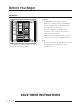
Before You Begin Important Installer • To promote safety and minimize problems, read this manual thoroughly before starting the installation. Leave this manual with the user. • Write the appliance’s model/serial numbers in this manual for service/ maintenance reference. • Model/serial numbers are on the data label in the Wine Cellar compartment. • The overall design and/or accessories may differ with the model.
Customer-Service Information If You Need Help If you have questions or problems with installation, contact your Dacor® dealer or the Dacor Customer Assurance Team. If your Dacor appliance is under warranty, call Dacor Distinctive Service. Have the appliance’s model/serial numbers available when you call. (These numbers are on the data label on the right-hand door jamb inside the ӥ͝ʪ ʀʪ̷̷ɇθ.) Dacor Customer Assurance Phone: 833-35-ELITE (833-353-5483) USA, Canada Mon – Fri 5:00 a.m. to 5:00 p.m.
Important Safety Instructions The Important safety instructions and warnings in these instructions are not meant to cover all possible problems and conditions that can occur. Use common sense and caution when installing, maintaining, or operating this or any other appliance. Always contact the Dacor Customer Assurance Team about problems and conditions that you don’t understand. See Customer-Service Information.
WARNING - R600a Refrigerant This appliance contains isobutane refrigerant, R600a, a natural gas with high environmental compatibility; however, it is also flammable. Please adhere to the warnings below • When handling, installing and operating the appliance, care should be taken to avoid damage to the refrigerant tubing. • Servicing shall be performed by manufacture-authorized service personnel and component parts shall be replaced with manufacturer-authorized replacement components.
Important Safety Instructions To avoid the possibility of explosion or fire, do not store or use combustible, flammable or explosive vapors and liquids (such as gasoline) inside or in the vicinity of this or any other appliance. Also keep items that could explode, such as aerosol cans away from cooktop burners, ovens and range hoods. Do not store flammable or explosive materials in adjacent cabinets or areas.
WARNING • • • • • • • • • • • • • • • To reduce the risk of fire, electric shock, serious injury or death when using your appliance, follow basic safety precautions, including the following: If you receive a damaged product, immediately contact your dealer or builder. Do not install or use a damaged appliance. Make sure that this appliance has been properly installed according to these installation instructions. Make sure to install in outlet locations according to electric supply location.
Important Safety Instructions • • • • • • If the power cord is damaged, it must be replaced by the manufacturer or a qualified service technician in order to avoid a safety hazard. Do not tamper with the controls. Clean this appliance regularly as instructed in the Care and Cleaning section of the User manual. Do not use any type of electrical equipment inside the wine cellar compartments. Do not obstruct any of the vents or openings on the appliance.
Safety and Warning Information Installation Safety WARNING • • • • • • • • • Before installing the wine cellar, connect it to a power outlet and turn the wine cellar ON to make sure the wine cellar is working. Choose a location away from a heater, boiler, or direct sunlight. Install the unit where air flows freely and where the wine cellar is well ventilated. Install the unit so that air flows unobstructed through the front air grill.
Safety and Warning Information DANGER Explosion Risk Keep flammable materials and vapors - such as gasoline - away from the wine cellar. Failure to do so can result in death, explosion, or fire.
Installation Specifications WARNING Observe all governing codes and ordinances during planning and installation. Contact your local building department for further information. WARNING Electrical and grounding connections must comply with the applicable portions of the national electrical code and/or other local electrical codes. This appliance comes with an electrical cord with a three-prong grounding plug for a 115 Vac, 15 Amp. power supply.
Installation Options There are many different installation options. These are limited only by the design of the kitchen.
Individual appliances with partition NOTE • The minimum thickness of the partition is 1 1/4” (32 mm). • At 1 1/4” (32 mm), the door swings must open towards as case 1. • At more than 1 9/16” (40 mm), the door swing can open same direction and door open angle is 90 degree as case 2. At more than 7 7/8” (200 mm), the door swing can open toward each other and door open angle is 90 degree as case 3. For this installation option it is recommend to install the 90 degree door stop.
Product Specifications B1 D2 D1 D F C G E 115° 90° B 16 English A Callout 24” A 23 3/4” (603 mm) B (With Panel) 25” (635 mm) B1 (Without Panel) 23 13/16” (605 mm) C 83 3/8” (2118 mm) D 23 5/8” (600 mm) D1 24 7/8” (631 mm) D2 27 9/16” (701 mm) E 50 3/4” (1289 mm) F 13 11/16” (348 mm) G 49 11/16” (1261 mm)
Custom Panel Specifications W1 H2 W3 H3 H1 W2 W2 Callout 24” W1 23 3/4” (603 mm) W2 3 9/32” (83.5 mm) W3 17 5/32” (436 mm) H1 79 7/8” (2029 mm) H2 7 23/32” (196 mm) H3 62 25/32” (1594.5 mm) H4 9 3/8” (238.5 mm) Panel Thickness 3/4” (19 mm) Max Weight 55.0 lb (25 kg) H4 Do not exceed the max load that the custom panel can endure. Before crafting the panel, check the strength of the panel’s material and the load of attachments to the panel. 24” Custom Panel Maximum Weight 55.
Product Specifications Handle Specifications Before installing the custom panels, you must first install the door/drawer handles. Handle Countersunk screw Custom panel Appliance door/drawer Handle Installation for Units with Custom Door Panels (Top View) With custom panel models, you have the advantage of being able to select a handle style that meets your own personal taste. Handles are not provided with custom panel models. Selected handle kits are available through your Dacor dealer.
Attach the Dacor Handle WARNING Follow these instructions to attach the Dacor handle. Otherwise, the handle may be damaged or malfunction. 1. Put the reinforced handle support on the rear of the door panel, and then put the handle on the front of the door panel. 2. As shown, tighten the 4 screws on each of the upper and the lower sides of the handle. Do not tighten them excessively.
Installation WARNING Do not install the appliance: • outdoors, • in an environment with dripping water. Appliance is very heavy : Wine Cellar 24” approx. 397 lb / 180 kg Installation room The appliance should be installed in a dry, ventilated room. Secure installation The appliance is very heavy and has a tendency to tilt forwards when the appliance door is opened. Do not open the door until there is no possibility of the appliance tipping over.
Installation Requirements Installation Preparation Cabinet installation parts Using the table on next page, verify that all installation parts are present as you unpack the appliance. A A1 C A2-1 D A2-2 E B F G Check the installation parts when unpacking.
Installation Requirements Door installation parts Using the table below, verify that all door-installation parts are present as you unpack the appliance. A' B' C' D' Check the installation parts when unpacking.
Tools required No. Tool No.
Installation Requirements Grounding the Wine Cellar CAUTION Electrical and grounding connections must comply with the applicable portions of the national electrical code and/or other local electrical codes. This appliance comes with an electrical cord with a three-prong grounding plug for a 115 Vac, 15 Amp. power supply. Plug it into a 115 Vac, three-prong, grounding electrical outlet only. DO NOT, UNDER ANY CIRCUMSTANCES, CUT OR REMOVE THE THIRD (GROUND) PRONG FROM THE POWER CORD.
Cabinet Special Requirements A : Cabinet Width Electric supply location B : Cabinet Depth C : Cabinet Height D : Electrical supply width location D 5” (127) A C E E : Electrical supply height location Callout 24” A 24” (610 mm) B 25” (635 mm) C 84” (2134 mm) D 14” (356 mm) E 80” (2032 mm) B • • B : Includes the standard door panel thickness with 3/4”. Installation inside a cabinet of this width allows the wine cellar trim to be attached directly to the surrounding cabinets.
Installation Instructions 1. Uncrating the Wine Cellar Check the appliance for transit damage. Do not install the appliance if it is visibly damaged. If in doubt, contact your dealer. 1. Remove the PP-banding, cardboard crate, EPS, and Pe-bag. 2. Remove the brackets from the pallet by unscrewing the bolts (five per bracket). M6x10 10 ea Unscrew the bolts CAUTION Use caution not to damage the appliance when unloading it from the pallet. 3.
2. Moving the Wine Cellar WARNING The appliance is very heavy. When moving the Ǯ̈͝ʪ Aʪ̷̷ɇθ, all personnel must take care not to injure themselves or the appliance. Ռ Secure the ӥ͝ʪ ʀʪ̷̷ɇθ to a suitable means of transport (preferably an appliance dolly), and move the ӥ͝ʪ ʀʪ̷̷ɇθ near its installation cabinet. Ս Move and install with a minimum of two persons. Վ Be very careful to avoid floor damage. Delicate flooring should be protected with plywood, hard cardboard, or similar material.
Installation Instructions 3. Installation Preparation Unpack installation materials and accessories. See the Installation preparation section on Installation Requirement chapter. 4. Attaching the Anti-tip-Bracket WARNING To keep the unit from tipping forward, an anti-tip bracket must be installed. Before attaching the bracket, ensure that no electrical wiring or plumbing is in the area where the screws will penetrate. One such bracket per appliance is required.
For 36” models, use 2 anti-tip brackets. Spacer (wood) A Cabinet Height 2” (50) Appliance Appliance Option Cabinet height A 1 83 1/2” (2121 mm) 79 13/32” (2017 mm) 2 83 3/4” (2127 mm) 79 5/8” (2023 mm) 3 84” (2134 mm) 79 7/8” (2030 mm) 4 84 1/4” (2140 mm) 80 1/8” (2036 mm) 24” ANTI-TIP BRACKET wooden wall concrete wall 1 ea M4x35 3 ea M4x35 3 ea ø6x30 3 ea (HOLDER LOCK) • 3 screws/holder locks per bracket.
Installation Instructions Anti-tip bracket considerations 1. Bracket positioning: follow the cabinetspecific height table. Wall 2. Screws: Tighten all 3 screws on the brackets. 3. Push the product up against the rear wall of the cabinet. Anti-Tip-Bracket Product 4. Spacer: If using the spacer, you must follow the positioning specifications of the bracket (see the table above). CAUTION • • The height of the spacer must be calculated based on the depth of the cabinet.
5. Removing Upper Door Cover, Kickplate You need to remove the upper door cap and kickplate before you adjust the custom door panel.
Installation Instructions 1. Remove the inner cover on the inner part of the upper door cover. 2. Disconnect the humidity sensor connector. 3. Remove the 2 screws fixing the upper door cover. 4. Remove the upper door cover from the fixers.
• Kickplate : For side-by-side installation, remove the grill cover. This is not applicable for standard one installation. 1. Push open the cover.Remove the screws on side and remove grill cover. WARNING Do not use impact drill. Can cause damage. 2. Remove the screws on both sides, and remove the kickplate.
Installation Instructions 6. Attaching Insulators on the Side of the Wine Cellar - Single Installation ϩϩɇʀ˵ Ս ̈͝ϑЇ̷ɇϩͱθϑ ͱ͝ ɇ͝ц ͱ͝ʪ ϑ̈ʒʪ ͱ˙ ϩ˵ʪ ӥ͝ʪ ʀʪ̷̷ɇθ Check your model first, and then attach the insulators by referring to the figure below. Attach the insulators to cover the screws on the chassis spacers. Align the insulators with the end of the center chassis spacer.
Ւ Attaching insulators on the side of the freezer or fridge ɇ͝ʒ Wine Cellar - Side-by-side (Pair) Installation Attach 2 insulators on any one side of the freezer or the fridge. The insulators are different in size according to the type. Check your model first, and then attach the insulators by referring to the figures below. Make sure a larger insulator is attached on the contact point. Attach the insulators to cover the screws on the chassis spacers.
Installation Instructions 2. When a freezer is on the right-hand side See the figures below for the layout after the insulator is attached.
Repositioning the Center Chassis Spacers 1. Remove the set’s center chassis spacer. 2. Re-attach the spacers 7/16 in. (10 mm) back from their original position (see graphic below).
Installation Instructions 8. Connecting the Two Chassis 1. Making the upper connection. - Attach the rectangular bracket to the protruding tabs on the top of each chassis (see the graphic). - Attach the lever to connect the two chassis. 2. Making the lower connection. - Insert the bracket in the groove at the bottom of the two chassis. - Attach the lever to connect the two chassis.
9. Adjusting the Uoor Opening Angle By factory default, the door opens by 115 degrees. You can use the limiter pin to adjust the opening angle down to 90 degrees, depending on the installation conditions. • Open the door to less than 90 degrees, and then completely insert the limiter pin through the top and bottom holes of the top hinge as shown in illustrations (1) and (2). • Close the door and make sure the limiter pin does not interfere with the hinge cover.
Installation Instructions 10. Moving the Wine Cellar Into Its Enclosure • According to the type of cabinet, a jig (positioning aid) can be used to align the Ǯ̈͝ʪ Aʪ̷̷ɇθٗs custom door panel with cabinet by marking vertical line on the cabinet. Overlay Frameless Jig (positioning aid) CAUTION Make sure to position the front of chassis spacer so that it is aligned with the vertical line. Otherwise, the installed Ǯ̈͝ʪ Aʪ̷̷ɇθ will tilt and its door may not close fully.
CAUTION As you push the wine cellar into its enclosure, take care not to damage the power cord. Also, arrange the power cord behind the appliance to ensure that it is not stepped on or over. WARNING While moving the wine cellar, take care not to harm assisting personnel or the ӥ͝ʪ ʀʪ̷̷ɇθ itself. Ռ Before moving the wine cellar, connect the power cord. Ս Place packaging cardboard or plywood in the ӥ͝ʪ ʀʪ̷̷ɇθٗs path to protect the flooring while moving the appliance.
Installation Instructions 11. Removing Two Levers • • To facilitate leveling on the wine cellar, remove the top and bottom levers to unpair the chassis. To disassemble lower lever, use a screwdriver by force.
12. Leveling the Wine Cellar Ռ Using your drill and the bit shown 10 mm bit below, engage each of the wine cellar’s adjuster shafts in turn, and level the ӥ͝ʪ ʀʪ̷̷ɇθ (CW y, CCW z) Ս Adjust the gap between the furniture and ӥ͝ʪ ʀʪ̷̷ɇθ top cover to 1/8 in. (3 mm). WARNING Do not use impact drill. Can cause damage. CAUTION • The front and rear leveling legs have a maximum height adjustment of 3/4” (20 mm).
Installation Instructions Front Rear Adjustable shaft (10 mm) Max 3/4”, 20 mm Jack type (height adjustment) 44 English
13. Attaching Two Levers • Attach the top and bottom levers to pair the chassis.
Installation Instructions 14. Attaching the Wine Cellar’s Top Cover The light intensity sensor is attached to the top cover. The wine cellar does not use the light intensity sensor, therefore do not connect the sensor connector. Product top view Wire connectors 1. Connect the wires for electric parts from around the Auto Door Open kit, and then insert the wires in the rectangular pipe. CAUTION Be careful not to damage the wires. Top cover 2.
15. Securing the Wine Cellar Secure the ӥ͝ʪ ʀʪ̷̷ɇθ to its enclosure with (TH) M4x16 screws (6 screws per side, as shown in the graphic). CAUTION Make sure the appliance is level. If the appliance is not level, the wine rack may slide in or out.
Installation Instructions 16. Attaching the Custom-Door-Panel Brackets Attach the panel brackets to the top and bottom of the panel. Custom Panel: STS Drive 10 screws each to the top and bottom brackets as shown in the graphic. (The other holes on each side of the bracket are for a different application.) (FH) M4x14 20 ea UPP : 10 ea / LOW : 10 ea Screw Hole Custom Panel: Wood, Other • • The template informs you the position of the bracket and holes.
Custom Panel: Recessed Back, Other If, by the nature of its design, the panel cannot be attached at the center of the bracket, use the whichever suitable screw holes on the sides of the bracket to attach the panel.
Installation Instructions 17. Hanging a Custom Panel WARNING If you install a custom panel before fixing the appliance to the cabinet, the custom panel can tip over. To prevent this, you must follow the installation instructions. • Hang the panel bracket on the height adjustment screw. (See the graphic.
18. Preparing the Panel for Adjustment 1. Fix the custom panel temporarily onto the side of the door by tightening the screw in the center of the panel. 2. Loosen—but do not remove—the six screws on the side of the door so you can adjust the custom panel vertically.
Installation Instructions 19. Aligning the Panel NOTE Each custom panel comes with 12 dedicated screws for fine-tuning. Use a minimum number of screws to fine-tune the custom panel with the cabinet. Once fine-tuning is complete, fix the custom panel with the top nut. There are two panel-adjustment mechanisms at the top and two at the bottom of the door. Adjust the panel so it aligns with the surrounding cabinetry.
Glass Door A B The gap between the glass door and the panel must be same on all sides (top, bottom, left, and right) or the difference should be no more than 2/32" (2 mm). (For example, if A is 2 mm, B should not exceed 4 mm.) Panel Top of the Door 1. Use the double-threaded bolts to align the door panel. 2. Engage a side screw (see the graphic) to shift the panel side to side. 3. Engage Screw 1 (see the graphic) to shift the panel forward/backward; engage Screw 2 to set the panel in place.
Installation Instructions 1. Engage Double Threaded Bolt (see the graphic) to shift the panel up and down. 2. Engage a side screw (see the graphic) to shift the panel side to side. CAUTION Be careful not to damage the wires when fastening the side screw. 3. Engage Screw (backward) (see the graphic) to shift the panel forward/backward; engage Screw (forward) to set the panel in place.
Top of Door Up/Low Left/Right Front/Rear Bottom of Door Left/Right Front/Rear Attaching the Panel to the Door 1. Screw nuts snugly onto the double-threaded bolts. 2. Fasten the screws to assemble the panel and the door as shown in the figure.
Installation Instructions 20. Attaching the Door’s Interior Covers Upper Door Cover 1. Connect the humidity sensor connector, and then arrange the wires as shown in the figure. 2. Assemble the inner cover. 3. Insert both side rings of the door cap of the upper door cover into the fixer.
Upper door cover 4. Fasten the 2 screws to fix the upper door cover.
Installation Instructions Lower Door Cover 1. Attach the air guide to the lower door cover (2 screws per set). 2. Attach the lower door cover by driving the screws from the front (2 screws per set). 3. Attach the caps over the screw holes.
21. Attaching Grill, Kickplate and Toe Kickplate (optional) Attaching grill • Drive the screws tightly on both sides to attach the grill. Otherwise, the door may not close fully. Attaching kickplate • Drive the screws on both sides to attach the kickplate.
Installation Instructions Attaching Toe kickplate • • • • The height of the product can be adjusted between 83 3/8” ~ 84 3/8”. If you want to use the provided Dacor toe kickplate (4”), note that it was designed for a product height of 83 7/8” and cabinet height of 84”. If you want to use a toe kickplate not provided by Dacor, adjust the height of the toe kickplate accordingly. You can extend the bracket to move the kickplate by a max of 32 mm to the front.
22. Attaching the Wine Cellar Trim 1. Cabinet-side trim: Attach the trim between the ӥ͝ʪ ʀʪ̷̷ɇθ and the cabinet. WARNING Please check again if there is any problem after installation. Top View Chassis spacer Cabinetside trim 2. Door-side trim: Attach trim to the door’s side bracket. • Refer to figure 1-X and secure the door side trim to the bracket. Make sure the trim is properly seated. • Refer to figure 2-Y and secure the door side trim to the door cover rib.
Installation Instructions 3. (Side-by-side installation only) Center trim: Attach the trim between the ӥ͝ʪ ʀʪ̷̷ɇθ chassis. WARNING Please check again if there is any problem after installation. Center trim 23. Attaching Trim Top Cover Attach the Trim Top Cover on the bottom of the Top Cover. • For pair installation, cut to fit the Trim Top Cover width and attach.
24. Assembling the Wine Rack 1. Remove the packaging of the bottom wine shelf, and then place it on the bottom of the wine cellar. 2. Remove the rail ˵ͱ̷ʒʪθ.
Installation Instructions 3. Hold the front part of the wine rack and the rail, and then push the wine rack so that the hook on the back of the rail is inserted into the hole on the back of the wine rack as shown in the figure. NOTE Make sure the hooks on both rails are properly inserted into the rack. 4.
Bottle Presenter 3 ea 5. Place 3 Bottle Presenter on the wine rack of the Presentation Zone. 6. Slide in the wine rack until you hear a clicking sound.
Installation Instructions WARNING • • Make sure the appliance is level. If the appliance is not level, the wine rack may slide in or out. Make sure the wine rack is firmly fixed. 25. Disassembling the Wine Rack 1. Pull the wine rack. 2. Gently spread the racks and lift the front part to release from the pins. 3. Pull the wine rack to remove.
26. Adjusting the Door Spring Adjust the tension of the door spring according to the product size. With a star-head screwdriver, turn the adjusting screw. I = maximum spring tension 0 = no spring tension 27. Cleaning Remove the protective vinyl.
Installation Instructions 28. Installation Checklist Ensure the wine ʀʪ̷̷ɇθ functions properly and that the custom door panel aligns with the surrounding cabinetry. WARNING • The following checklist should be completed by the installer to ensure that the wine ʀʪ̷̷ɇθ is safely and correctly installed, functions properly, and that no part of the • installation has been overlooked. Proper installation is the responsibility of the homeowner.
Memo
Memo
Memo
DA68-03621J-01 Dacor ∙ 14425 Clark Avenue, City of Industry, CA 91745 ∙ Phone: (800) 793-0093 ∙ Fax: (626) 403-3130 ∙ www.dacor.