Installation Instructions Modernist Gas Cooktop DTG30M954F/DTG36M955F Part No.
Contents Before you begin 3 About this manual Important note to the installer Important note to the consumer Important note to the servicer 3 3 3 3 Customer-service information 4 4 5 Read all instructions before using this appliance Symbols used in this manual State of California Proposition 65 warning (US only) Commonwealth of Massachusetts 5 5 5 5 Safety and warning information 6 6 7 7 8 8 9 10 11 What’s in the box 11 Installation requirements 13 Pre-installation checklist Location requireme
Before you begin About this manual READ THESE INSTRUCTIONS COMPLETELY AND CAREFULLY. Important note to the installer • • • • • • • Read all instructions in these installation instructions before installing the cooktop. Remove all packing materials from the cooktop compartments before connecting the electric and gas supply to the cooktop. Observe all governing codes and ordinances. Be sure to leave these instructions with the consumer. Installation of this appliance requires basic mechanical skills.
Customer-service information If You Need Help... If you have installation issues, contact your Dacor dealer or the Dacor Customer Assurance Team. Before you call, have available the cooktop's model/serial numbers, which are on the rating label (front-left side of the cooktop chassis). Rating Label Dacor Customer Assurance Phone: (800) 793-0093 x2813 (USA, Canada) Hours of Operation: Mon – Fri 5:00 a.m. to 5:00 p.m. Pacific Time Website: www.dacor.
Important safety instructions READ ALL INSTRUCTIONS BEFORE USING THIS APPLIANCE • • Electrical and gas equipment with moving parts can be dangerous. The important safety instructions in this manual are intended to minimize the risk of property damage, personal injury, and death. Be sure to read them. Keep this manual in a handy place so you can refer to it as needed. Symbols used in this manual WARNING Hazards or unsafe practices that may result in severe personal injury or death.
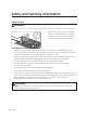
Safety and warning information General safety WARNING To reduce risk of fire, electric shock, personal injury, or death, observe these precautions: • • • • • • • • • • • Do not touch any part of the cooktop during or immediately after cooking. Learn where and how to shut off the valve that feeds gas to the cooktop. Make sure the cooktop's hold-down brackets are properly installed. (See pg. 26.) Do not let children sit/stand on the cooktop or play with any of its parts.
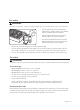
Fire safety WARNING To reduce risk of fire, electric shock, personal injury, or death, observe these precautions: • • • • • • Do not store/place/use combustible material (e.g., paper, plastic, pot holders, linens, alcohol) near the cooktop. Do not wear loose fitting or hanging clothing while using the cooktop. Do not let flammable material touch a heating element. Do not use a towel or other bulky cloth as a pot holder. Regularly clean the vents to remove grease buildup.
Electrical and grounding safety WARNING To reduce risk of fire, electric shock, personal injury, or death, observe these precautions: • • • • • • • • • • • • • Plug into a grounded, 3-prong outlet. Do not remove the ground prong. Do not use an adapter or extension cord. Do not use a damaged power plug, cord, or loose power outlet. Do not modify the plug, cord, or outlet. Do not put a fuse in a neutral or ground circuit. Use a dedicated 120-volt, 60-Hz, 15-amp, AC, fused electrical circuit.
Safety and warning information Installation safety WARNING To reduce risk of fire, electric shock, personal injury, or death, observe these precautions: • The cooktop should be installed and properly grounded by a qualified installer, as specified in this manual. Adjustments and service should be performed only by qualified installer or service technician. • Do not service/modify/replace the cooktop or any part of it unless directed in this manual.
Safety and warning information Cooktop safety WARNING To reduce risk of fire, electric shock, personal injury, or death, observe these precautions: • • • • • • • • • • • • • • • • • • • • • • Turn off all burners that are not in use. Do not line the grates or any part of the cooktop with aluminum foil. Do not leave burners unattended on medium or high heat settings. Before igniting, ensure the burner components are properly seated.
Gas cooktop components What’s in the box Parts supplied Common Manual Screw (6) (M4 L10 2 ea, M4 L16 2 ea, 24 3/16 UNC L145 nut toggle 2 ea) Regulator (1) * Surface burners, brass caps (4) Porcelain caps (4) Surface burners, brass caps (5) Porcelain caps (5) Hold down brackets (2) * 30” : DTG30M954F* Cooktop burner grates (2) 36” : DTG36M955F* Cooktop burner grates (3) NOTE • • • Before installation, verify all of the parts above are present.
Parts needed Gas line shut-off valve 135-degree elbow (optional) Flexible metal Flare union adapter ¾ Flare union adapter ½ appliance connector in or ½ in (NPT) x ½ in (NPT) x ½ in (ID) ½ in (ID) x 5 ft in (ID) 90-degree elbow (optional) Tools needed Flat-blade screwdriver Phillips screwdriver Open-end or adjustable wrench Pipe wrench (2) ¼" Nut driver Pencil and ruler Level Pipe joint compound Utility knife Soapy water solution Pliers Saber saw 12 English
Installation requirements Pre-installation checklist 1. Before preparing the countertop opening, verify there will be no conflict between the cooktop chassis and anything in the cabinet below. 2. Remove packing material, grate boxes, regulator with literature, and literature package, verify that all items are present before beginning the installation. Location requirements Before installing the cooktop, see the information and graphic below. These dimensions must be met for safe cooktop operation.
Overall cooktop dimensions DTG30M954F* A ⅓" (8 mm) countertop to grate surface 6" (152.4 mm) chassis Height C B D DTG36M955F* A ⅓" (.8 cm) countertop to grate surface 6" (15.2 cm) chassis height C B D Model A B DTG30M954 30” (76.2 cm) 28½” (72.3 cm) DTG36M955 36” (91.4 cm) 34½” (87.5 cm) 14 English C D 21” (53.3 cm) 19½” (49.
Installation requirements Cutout dimensions of countertop CAUTION Cutout dimensions should be strictly observed. Rear wall Vertical combustible surface H E G F H Model DTG30M954 (no downdraft) DTG30M954 with MRV3015M/S DTG36M955 (no downdraft) DTG36M955 with MRV3615M/S (E) Min. Minimum distance to combustible side wall above countertop (both sides) (F) Min. (G) Min. (H) Min. 2⅞” (7.2 cm) 19¾” (50.1 cm) ⅜” (0.9 cm) 2811/16” 12” (30.4 cm) 22½” (57.1 cm) (72.7 cm) 7½” (19.0 cm) 2⅞” (7.
⅜" min. (1.0 cm) required for downdraft cap clearance Countertop 23 ⅜" (59.4 cm) Stiffener Cabiner face ⅜" min. (1.0 cm) space behind downdraft to clear stiffener MRV Series Downdraft: check downdraft specifications to determine correct fit Cooktop with Downdraft: MRV Series Utility locations and dimensions Front of unit Front of cooktop 1¾" (4.5 cm) Chassis Power cord 393/8” (100.0 cm) long 3¾" (9.6 cm) /8”-18 NPT male gas inlet 3 16 English * Gas inlet protrudes 14/7 (4.0 cm) from bottom.
Installation requirements Gas supply requirements Provide adequate gas supply Be sure to supply your cooktop with the gas for which it is designed. Do not try to convert the cooktop to receive a different type of gas without consulting the gas supplier. This cooktop converts to natural or propane gas. For LP gas, conversion must be made by a qualified installer before operating the cooktop. For proper natural-gas operation, the pressure supplied to the regulator must be 5 – 13 in.
Electrical requirements WARNING The owner shall ensure the electrical service meets electrical requirements and that the electrical outlet is properly installed by a licensed electrician. • To reduce risk of fire, electric shock, or personal injury: - Do not use an extension cord or adapter plug with this cooktop. - The power cord has an equipment-grounding conductor and a grounding plug. - Ensure a properly grounded outlet is installed by a qualified electrician.
Installation instructions Installing your gas cooktop IMPORTANT: Carefully read these instructions and the Important Safety Instructions section at the front of this manual BEFORE installing/operating the cooktop. Improper installation, adjustment, service, or maintenance can lead to personal injury and property damage. NOTE To ensure proper installation, you should hire a qualified professional. Unpacking the cooktop 1. Remove all packaging material. 2.
Connecting the gas supply 1. Shut off the main gas-supply valve before disconnecting the old cooktop. 2. Complete the gas hookup. 3. Open the gas valve, and relight the burners on any other gas appliances. NOTE Because hard piping restricts movement of the cooktop, use a CSA International-certified flexible metal appliance connector unless local codes require hard piping.
Installation instructions Never install an old connector on a new cooktop. For hard piping, carefully align the pipe; the cooktop cannot be moved once the connection is made. To prevent gas leaks, apply pipe-joint compound or wrap pipe-thread tape with Teflon on all male (external) pipe threads. 1. Attach the provided gas-pressure regulator to the cooktop pipe nipple inlet. (For tight installations, the regulator may be installed upstream from the nipple, anywhere between the shut-off valve and the cooktop.
Checking for gas leaks WARNING To prevent an explosion/fire hazard possibly leading to personal injury or death, DO NOT use a flame to check for gas leaks. When using pressures above 1/2 psig to test the home gas-supply system, disconnect the cooktop and individual shut-off valve from the gas-supply piping. When using pressures of 1/2 psig or less to test the gas-supply system, isolate the cooktop from the system by closing the individual shut-off valve. 1.
Installation instructions Assembling the cooktop burners CAUTION • • • Ensure all burner parts are in place before operating the cooktop burners. Do not push in any cooktop controls while removing the burner; you might receive an uncomfortable electrical shock. Do not touch one burner's electrode while another burner is on. 1. Put the burner heads on their bases as shown at left. (The electrodes fit in the slot in the bottom of the heads.) The heads should be flat and parallel to the cooktop. 2.
Dual Burner head / caps 1. Orient the burner head so the opening for the electrode aligns with the electrode. 2. Install the burner head so the electrode passes through its opening in the head. Ensure the burner head lies flat on the stove top. 3. Match the burner caps to the burners by size, then install the caps on the heads.
Installation instructions NOTE • • For NG For LP Round Burner head / caps The included dual burner head is not a substitute. One is for LP gas and the other is for LN gas. Use appropriate gas type. - Dual burner head for LP gas is packed with a plastic bag. - The letter "For LP" or "For NG" is engraved on the dual burner head. LP burner head also can be found by the number of holes. - The burner head with 14 holes in a quadrant is for LP gas use.
Verifying burner function After the cooktop is fully installed, connected, assembled, and plugged in, verify burner function. Perform this procedure for each burner in turn. To turn on a cooktop burner 1. Push in, and turn a burner control knob to the "Lite" position (flame icon). A "click-click-click...” indicates the electronic ignition system functions. The burner ignites in about 4 seconds , after air is purged from the gas line.) 2. Turn the knob to the desired setting.
Installing the grates NOTE For best results and longest life, install the grates as instructed below. When installed properly, the openings in the grates are centered over the burners. The three grates occupy specific positions on the cooktop. For maximum stability and safe operation, these grates should only be used in their proper positions. The back of the right grate is notched to help orient the grates correctly. (See the graphic below.) To correctly position the grates: 1.
Installation instructions Final installation checklist WARNING The owner shall be responsible for the cooktop's proper installation. After installing the cooktop, the installer should review this checklist to confirm the cooktop is properly installed and ready to operate. • • • • • • The gas line is properly connected to the cooktop. The gas is turned on. All connections were checked for leaks. The cooktop is properly plugged in to a grounded electrical outlet.
Installation instructions Supplied parts The following parts make up the LP conversion kit: ORIFICES/ORIFICES/ORIFICIOS LR MAIN(LIGHT BLUE) SUB(BROWN) RR MAIN(LIGHT GRN) SUB(PINK) ORIFICES/ORIFICES/ORIFICIOS LR MAIN(LIGHT BLUE) SUB(BROWN) RR MAIN(LIGHT GRN) SUB(PINK) CENTER MAIN(PUR) SUB(GRAY) LF MAIN(PUR) SUB(GRAY) RF MAIN(LIGHT GRN) SUB(PINK) DG69-00306A DG96-00581A (ASSY NOZZLE-KIT) DTG30M954 LF MAIN(LIGHT BLUE) SUB(BROWN) RF MAIN(LIGHT GRN) SUB(PINK) DG69-00305A DG96-00582A (ASSY NOZZLE-KIT)
BURNER ORIFICE SIZES AND OUTPUT RATINGS (LP Gas [Propane] 10 in WCP) Burner Location BTU Rate Orifice Size (mm) Main / sub RF 7,500 0.7 / 0.42 LF¹ 14,500 In 0.46 / Out 0.74 (2 pcs) LF² 10,500 0.82 / 0.5 RR 7,500 0.7 / 0.42 LR 10,500 0.82 / 0.5 CTR² 14,500 In 0.46 / Out 0.74 (2 pcs) BURNER ORIFICE SIZES AND OUTPUT RATINGS (Natural Gas 5 in WCP) Burner Location BTU Rate Orifice Size (mm) Main / sub RF 9,500 1.20 / 0.61 LF¹ 18,500 In 0.70 / Out 1.27 (2 pcs) LF² 13,000 1.41 / 0.
Installation instructions NOTE 115 Orifice markings: 115 – Denotes 1.15 mm orifice size opening. Required tools Adjustable wrench ½” open-end wrench Small flat-bladed precision screwdriver Nut drivers: 9/32” or 7 mm Screwdrivers: Phillips To convert the cooktop for LP gas, perform these steps: 1. Disconnect electrical power to the cooktop. (Unplug the cooktop, trip the circuit breaker, or remove the fuse.) 2. Close the manual shut-off valve to cut the gas supply to the cooktop.
Converting the pressure regulator NOTE If you use LP gas, these steps and conversions must be made before adjusting the flames. 1. Using your fingers, turn the cap. And carefully look at the spring retainer to locate the NAT or LP position. LP Cap Gasket NAT NAT LP LP NAT LP NAT LP NAT. Position Spring Retainer L.P./Propane Position Pressure Regulator 2. Rotate the spring retainer 90°, and pull it from the cap.
Installation instructions Converting the cooktop burners NOTE If you use LP gas, these steps and conversions must be made before adjusting the flames. 1. Lift off the cooktop burner caps and the cooktop burner heads from the cooktop burner bases or the cooktop burner cups. Cooktop Burner Locations Burner Cap Burner Head Burner Base 2. Using a 9/32” or 7 mm nut driver, remove the burner orifice from the bottom of each burner cup.
NOTE Save these orifices and note their positions for future conversions back to natural gas. 3. Locate the LP conversion orifices that were shipped with the cooktop. 4. Identify the proper orifice by orifice size for each of the cooktop burners. 5. Install the proper orifice in each burner cup, and tighten with a 9/32” or 7 mm nut driver. NOTE Wrongly located orifices could result in dangerous operating conditions and poor cooking results. 6.
Installation instructions 4. With a small, flat-bladed screwdriver, adjust the bypass valve screw in the base of the valve stem. Turn the bypass valve screw counterclockwise to increase the flame size. Inner flame bypass screw Flat-bladed screwdriver Inner flame bypass screw Outer flame bypass screw Dual valve 5. Replace control knob and recheck the low flame setting. 6. Repeat Step 1 – 5 to check and adjust the low-flame settings on the remaining burners. Combustion flame quality 1 2 1.
DG68-00926A-00 Dacor ∙ 14425 Clark Avenue, City of Industry, CA 91745 ∙ Phone: (800) 793-0093 ∙ Fax: (626) 403-3130 ∙ www.dacor.