Installation Instructions Modernist Rangetop DTT48M876*/DTT36M876* Part No.
Table of Contents Before You Begin 3 Important Notes 3 Customer-Assurance Information 4 Important Safety Instructions 5 Product Specifications 9 What Is In the Box Parts and Tools Needed 9 10 Installation Requirements 11 In Preparation Overall Rangetop Dimensions Countertop Cutout Dimensions Gas-Supply Requirements Special Gas Requirements (gas models sold in Massachusetts) Electrical Requirements 11 12 13 17 17 18 Installation Instructions 19 Installing the Rangetop 19 2 English
Before You Begin Important Notes to the Owner User • Keep this manual for personal and professional reference. • Ensure that qualified personnel install and ground the rangetop. Overall design/accessories may differ with the model. Installer • Read this manual thoroughly before installation. • Leave this manual with the user. • Write the rangetop's model/serial numbers in this manual for service/maintanance reference.
Customer-Assurance Information To resolve questions and installation issues, contact your Dacor dealer or the Dacor Customer Assurance Team. Before calling, have the rangetop's model/serial numbers available (see the data label, right-hand side of the rangetop chassis.) Label Dacor Customer Assurance Phone: (800) 793-0093 x2813 (USA, Canada) Hours of Operation: Mon – Fri 5:00 a.m. to 5:00 p.m. Pacific Time Website: www.dacor.
Important Safety Instructions Read All Instructions Before Using This Appliance • All electrical and gas equipment with moving parts can be dangerous. Read the Important Safety Information, and follow the instructions carefully to minimize risk of property damage, personal injury, and death. • Keep this manual in a handy place for personal and professional reference. Symbols In This Manual Follow these warning icons and symbols explicitly to prevent property damage and personal injury.
Important Safety Instructions General Safety, cont. • Do not use the rangetop as a space heater. • Air curtains or range hoods that blow air downward shall not be used with a gas range unless the hood and range are designed and tested according to the Standard for Domestic Gas Ranges, ANSI Z21.1 • CSA1.1, and listed by an independent testing laboratory for combination use. Fire Safety To reduce risk of property damage, fire, personal injury, and death: • Do not store/place/use combustible items (e.g.
Important Safety Instructions Electrical and Grounding Safety To reduce risk of property damage, fire, personal injury, and death: • Plug the appliance in to a grounded, 3-prong outlet. • Do not remove the ground prong. • Do not use an adapter or an extension cord. • Do not use a damaged power plug/cord, or loose power outlet. • Do not modify the power plug, cord, or outlet. • Do not put a fuse in a neutral or ground circuit. • Use a dedicated 120-volt, 60-Hz, 20-amp, AC, fused electrical circuit.
Important Safety Instructions Rangetop Safety To reduce risk of fire, electric shock, personal injury, and death: • Turn all burners are off when not in use. • Do not use aluminium foil to line the grates or any part of the rangetop. • Do not leave burners unattended on medium or high heat settings. • Before igniting, ensure all burner caps are properly in place and all burners are level. • Always use the LITE ( ) position to ignite the burners, then ensure the burners ignite.
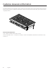
Product Specifications What Is In the Box Commons Parts 36" DTT36M876L* Cooktop burner grates (3) Burner heads (4) and Brass caps (5) Porcelain caps (6) 48" : DTT48M876L* Cooktop burner grates (3) Burner heads (4) and Brass caps (5) Porcelain caps (6) • Verify that all supplied parts are present. • If your rangetop was damaged during shipping or specified parts are missing, contact your local retailer. Do not install a damaged or incomplete rangetop.
Product Specifications Parts and Tools Needed Parts Needed Gas line shut-off valve Flexible metal appliance connector ½ in (ID) x 5 ft 135-degree elbow (option) Flare union adapter ¾ Flare union adapter ¾ in (NPT) x ½ in (ID) in (NPT) x ½ in (ID) 90-degree elbow (option) Tools Needed Flat-blade screwdriver ¼" Nut driver Pipe-joint compound 10 English Phillips screwdriver Pencil, ruler Soap-water solution Open-end or adjustable wrench Level Pliers Pipe wrench (2) Pipe-joint compound Saber
Installation Requirements In Preparation 1. Before cutting the opening in the countertop, verify that there will be no conflict between the rangetop chassis and anything in the cabinet below. 2. Remove all packing material and accessories from the rangetop, and verify that all items are present before beginning the installation. Location Requirements Before you begin the nstallation, review this section thoroughly. These dimensions must be met for safe operation.
Installation Requirements DTT36M876* 36” (91.1 cm) DTT48M876* 48” (121.
Installation Requirements Countertop Cutout Dimensions Cabinet/Countertop Dimensions (front view) Installed Rangetop (side view) Cutout dimensions must be observed. Any overage could be create severe problems. Cabinet tolerances +1/16” (+1.6 mm) -0 unless otherwise noted.
Installation Requirements Countertop Cutout Dimensions, cont. Installed Rangetop (side view) Cabinet/Countertop Cutout Dimensions—No Downdraft Vent (top view) 14 Rangetop Model A B C DTT36M876L* 36” (91.4 cm) 35” (88.9 cm) 16 5/8” (42.2 cm) DTT48M876L* 48” (121.9 cm) 47” (119.4 cm) 20 13/16” (52.
Installation Requirements Countertop Cutout Dimensions, cont.) Cabinet/Countertop Cutout Dimensions—With Downdraft Vent (top view) Gas and electrical connections must be routed through the bottom of the rangetop when installed with a downdraft vent. Model A: Cutout Width B: Hole Offset C: Downdraft Vent Cutout Approved Downdraft Vent Models* DTT36M876L* 36” (91.4 cm) 16 5/8” (42.2 cm) 33 1/2” (85.1 cm) MRV3615M/S DTT48M876L* 48” (121.9 cm) 20 13/16” (52.9 cm) 43 1/2” (110.
Installation Requirements Countertop Cutout Dimensions, cont. Cabinet/Countertop—With Downdraft Vent (side view) Utility Locations and Dimensions (rear) 16 Dimension DTT36M876L* DTT48M876L* D 3 1/2" (8.9cm) 4" (10.1cm) E 4 11/16" (11.9cm) 4 11/16" (11.9cm) F 5 1/8" (13cm) 16 1/2" (41.9cm) G 2 11/16" (6.9cm) 2 11/16" (6.
Installation Requirements Gas-Supply Requirements Provide Adequate Gas Supply The rangetop operates at a manifold pressure of: • 5 in. (13 cm) of water column for natural gas/natural-gas-at-high-altitude (NG-H) or • 10 in. (25 cm) of water column for LP gas (propane)/LP-gas-at-high-altitude (LP/H). Ensure your rangetop receives the proper gas. When verifying regulator function, the inlet pressure must be at least 1 in. (2.5 cm) greater than the given operating (manifold) pressure.
Installation Requirements Electrical Requirements • The owner shall verify that the electrical service meets electrical requirements and that the outlet is properly installed by a licensed electrician. • To reduce risk of fire, electric shock, or personal injury: –– Do not use an extension cord or adapter plug with the rangetop. –– The rangetop must be properly grounded. –– Do not use a damaged power plug or loose wall outlet. –– Do not modify, remove, or otherwise defeat the plug's grounding (3rd) prong.
Installation Instructions Installing the Rangetop IMPORTANT Carefully read these instructions and the Important Safety Instructions (Pg. 5) before installing/ operating the rangetop. Improper installation, adjustment, service, or maintenance can lead to personal injury and property damage. Product failure due to improper installation is not warrantied. Only qualified personnel should install the rangetop. Unpacking the Rangetop 1. Remove all packaging. (Failure to do so could damage the rangetop.) 2.
Installation Instructions Installing the Rangetop, cont. Connecting the Gas Supply, cont. Never install an old connector on a new appliance. For hard piping, carefully align the pipe; the rangetop cannot be moved after the connection is made. To prevent gas leaks, apply pipe-joint compound or wrap pipe-thread tape with Teflon on all male (external) pipe threads. 1. Attach the provided gas-pressure regulator to the rangetop pipe nipple inlet.
Installation Instructions Installing the Rangetop, cont. Making the Electrical Connections • Disconnect power at the main circuit breaker or fuse box before making electrical connections. • BEFORE operating/testing, follow the grounding requirements (pg. 30) of this manual. Improper connection of the grounding plug is an electric-shock risk. • The electrical system (including power cord) is factory-installed/-wired. Altering any part of this system may cause a short or overload. 1. Plug in the power cord.
Installation Instructions Installing the Rangetop, cont. Dual Burner Heads/Caps 1. Orient the burner head so the opening for the electrode aligns with the electrode. 2. Install the burner head so the electrode passes through its opening in the head. Ensure the burner head lies flat on the stove top. 3. Size the burner caps to the burners, then install the caps on the heads. Round Burner Head/Caps 1. Put the burner heads on the burner bases. The bottom of the head fits within the burner base. 2.
Installation Instructions Rack and Pan Placement 1. Place the burner heads as shown. The locater tab on the head goes in the keyed hole as shown. 2. Put the burner rings on the heads as shown. Match the tabs on the bottom of the ring to the slots on the head. Wiggle each ring to ensure it is properly seated. 3. Put the burner caps on the burner rings. The ridge around the bottom edge of the cap fits around the top of the ring.
Installation Instructions Installing the Rangetop, cont. Checking Flame Quality All burner flames must be visually checked to assess their quality. If you want measure the flame, take care to avoid burn injuries. 1. Soft blue flames—Normal for natural gas. 2. Yellow tips on outer cones—Normal for LP gas. 3. Yellow flames—Abnormal for any gas operation. If the burner flame looks like Ex. 3, call for service, and do not use the rangetop. Ex. 1 or 2 are normal burner flames.
Installation Instructions Installing the Rangetop, cont. Final Installation Checklist After installing the rangetop, ensure all control knobs are OFF. Review this checklist to confirm the rangetop is properly installed and ready to operate. • The gas line was properly connected to the rangetop. • The gas was turned on. • All connections were checked for leaks. • The rangetop is properly plugged in to a grounded electrical outlet. • The rangetop burners and grates are properly assembled.
Notes 26 English
Notes English 27
Please visit www.dacor.com to activate your warranty online. WARRANTY INFORMATION IMPORTANT: Your warranty will not be activated until you activate it online or return this form to Dacor. If you have purchased more than one Dacor product, please return all forms in one envelope, or activate the warranty online for each product. Owner Last Name (please print) First Middle Init.
fold here NO POSTAGE NECESSARY IF MAILED IN THE UNITED STATES BUSINESS REPLY MAIL FIRST-CLASS MAIL PERMIT NO 1600 CITY OF INDUSTRY CA POSTAGE WILL BE PAID BY ADDRESSEE DACOR ATTN WARRANTY PROCESSING DEPT PO BOX 90070 CITY OF INDUSTRY CA 91715-9907